- genevb's home page
- Posts
- 2024
- 2023
- 2022
- September (1)
- 2021
- 2020
- 2019
- 2018
- 2017
- December (1)
- October (3)
- September (1)
- August (1)
- July (2)
- June (2)
- April (2)
- March (2)
- February (1)
- 2016
- November (2)
- September (1)
- August (2)
- July (1)
- June (2)
- May (2)
- April (1)
- March (5)
- February (2)
- January (1)
- 2015
- December (1)
- October (1)
- September (2)
- June (1)
- May (2)
- April (2)
- March (3)
- February (1)
- January (3)
- 2014
- 2013
- 2012
- 2011
- January (3)
- 2010
- February (4)
- 2009
- 2008
- 2005
- October (1)
- My blog
- Post new blog entry
- All blogs
Distortion Maps of Varied TPC Field Cage Short Positions
Updated on Tue, 2017-04-18 13:33. Originally created by genevb on 2017-04-18 00:11.
NB: Additional documentation on You do not have access to view this node.
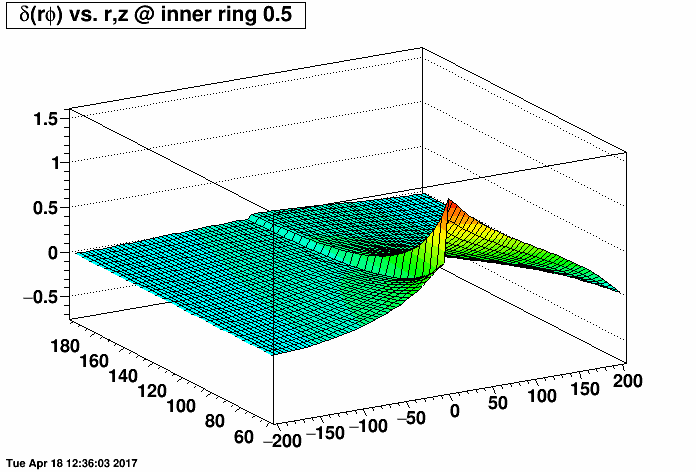
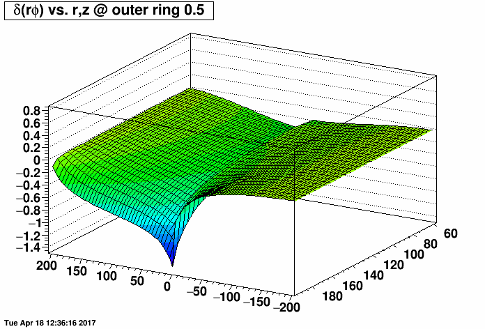
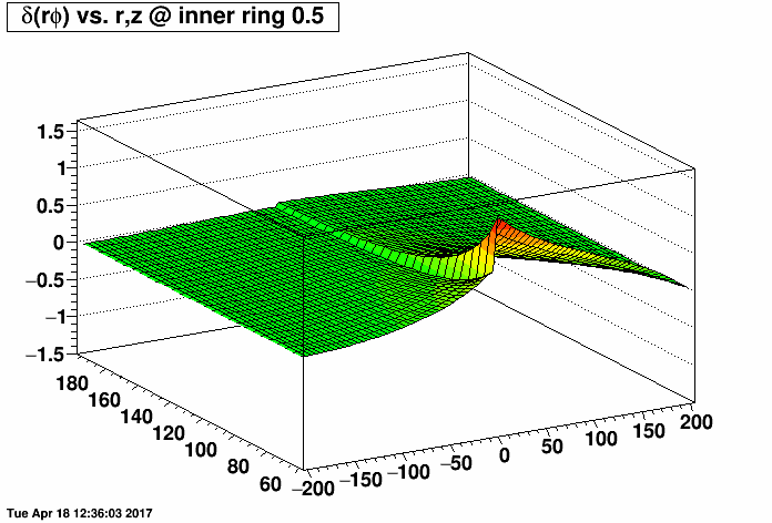
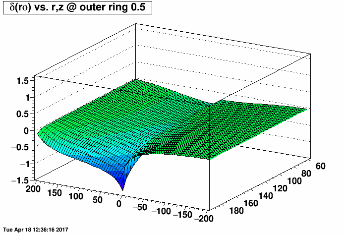
I placed a 2.0 MΩ field cage short (one entire resistor's worth) on the east TPC (z < 0) and the same 2.0 MΩ short on the west TPC (z > 0) at the same rings but with a compensating MΩ resistor placed outside the TPC (before ground) to restore the proper total current through the field cage. I then varied the rings where the short was from 0.5 (between rings 0 and 1, where ring 0 is the central membrane) to 10.5, 20.5, ...up to 180.5. There are 182 resistors in the chain. I then made distortion maps of δ(rφ) vs. r and z (r ranging from 60 to 200 cm, and z ranging from -200 to 200 cm) under a Reversed Full Field condition. All units are [cm].
I did this for the inner TPC field cage (first plot, where the distortions are largest at small radii near r=60 cm) and outer TPC field cage (second plot, where the distortions are largest at large radii near r=200 cm) to generate the following animations of the rφ distortion. These plots demonstrate that the distortions are generally worse with a compensating resistor than without, unless the short is in the outermost ~30-40 rings (i.e. between rings out beyond ring ~140).
Note that compensating resistors create a "plateau" region for long drift distances because with the proper current, the field cage rings are at the appropriate potentials near the central membrane and do not add further to distortions accumulated near the endcaps. In contrast, without a compensating resistor the errant potentials on the central membrane side of the shorts create a compensating reversal of the distorting force from the potentials on the endcap side of the short, which can minimize the net distortion for long drift distances.
Below are the exact same data as in the two plots as above, but fixing the vertical range to be the same for both IFC and OFC shorts so that green represents the smallest distortions in both plots.
-Gene
»
- genevb's blog
- Login or register to post comments