BEMC Detector Operator Manual
Authored by O. Tsai, 04/13/2006 (updated 02/02/2011)
You will be operating three detectors:
| BTOW | Barrel Electromagnetic Calorimeter |
| BSMD | Barrel Shower Maximum Detector |
| BPSD | Barrel Preshower Detector |
All three detectors are delicate instruments and require careful and precise operation.
It is critical to consult and follow the “STAR DETECTOR STATES FOR RUN 11”
and “Detector Readiness Checklist” for instructions.
Rule 1: If you have a concern of what you are going to do with any of these detectors please don’t hesitate to ask people around you in the control room or call experts to get help or explanations.
This manual will tell you:
- how to turn On/Off low and high voltages for all three detectors.
- how to prepare BTOW for “Physics”.
- how to recover from a PMT HV Trip.
- how to deal with common problems.
First, familiarize yourself with the environment of the control room. This is a picture of the four terminal windows which you will be using to operate the BEMC systems. For run 11, Terminal 4 is not in use. Terminal 0 (not shown) is on the left side of terminal 1/
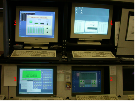
(clicking on a link will take you directly to that section in the manual)
0 - (on beatrice.starp.bnl.gov)
1 - (on emc02.starp.bnl.gov)
BEMC PMT Low Voltage Power Supply Slow Control
2 - (on emcsc.starp.bnl.gov)
BTOW HV Control
3 - (on hoosier.starp.bnl.gov)
BSMD HV Control
0 - (on emc01.starp.bnl.gov)
BPSD HV Control
To login on any of these computers use the emc account with password (check the control room copy of the manual).
Terminal 0 “BEMC Main Control Window”
Usually this terminal is logged on to beatrice.starp.bnl.gov
The list of tasks which you will be doing from this terminal is:
- Prepare BEMC detectors for Physics.
- Turning On/Off low voltages on FEEs.
- Turning On/Off BEMC crates.
- Resetting Radstone Boards (HDLC).
- Explain to experts during phone calls what you see on some of the terminals.
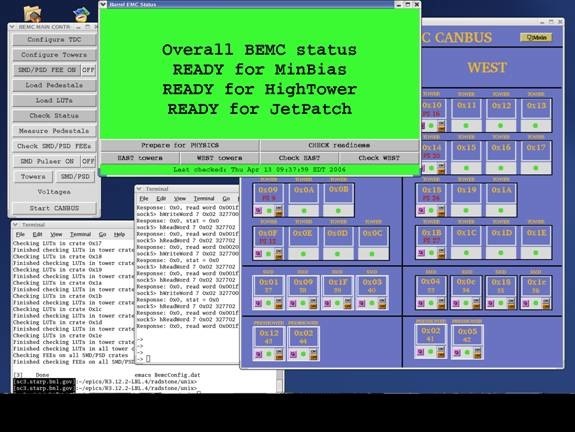
The screenshot above shows how the display on emc02.starp.bnl.gov usually looks during the run. There are five windows open all the time. They are:
- “Barrel EMC Status” - green.
- “BEMC MAIN CONTROL” – gray.
- “BARREL EMC CANBUS” – blue.
- Terminal on sc5.starp.bnl.gov (referred to as the ‘sc5 window’)
- Terminal from telnet scserv 9039 (referred to as ‘HDLC window’)
Prepare BEMC detectors for PHYSICS.
In normal operation this is a one click operation.
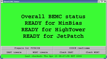
Click “Prepare for PHYSICS” button and in about 10 minutes “Barrel EMC Status” window will turn green and tell you that you are ready to run. This window may look a little bit different from year to year depending trigger requirements for BTOW.
However if this window turns red, then you will be requested to follow the suggested procedures which will popup on this window: simply click on these procedures to perform them.
During “prepare for physics” you can monitor the messages on the sc5 window. This will tell you what the program is actually doing. For example, when you click “Prepare for Physics” you will start a multi-step process which includes:
- Turning OFF FEEs on all SMD/PSD crates
- Programming TDC (Tower Data Collector, Crate 80)
- Reprogramming FPGAs on all BTOW crates
- Configuring all BTOW crates
- Configuring all SMD/PSD FEEs
- Loading pedestals on all BTOW crates
- Loading LUTs on all BTOW crates (only for pp running)
- Checking BTOW crate configuration
- Checking SMD/PSD configuration
- Checking that pedestals were loaded correctly (optional)
- Checking that LUTs were loaded correctly (only for pp running)
Usually, you will not be asked to use any other buttons shown on this window.
BEMC MAIN CONTROL
You can initiate all steps outlined above manually from the BEMC MAIN CONTROL window shown below, and do much more with the BEMC system. However, during normal operation you will not be asked to do that, except in cases when an expert on the phone might ask you to open some additional window from this panel and read back some parameters to diagnose a problem.
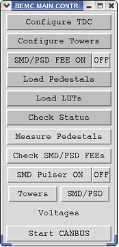
You might be asked to:
- Turn OFF or ON SMD/PSD FEE
- Open SMD/PSD panel and read voltages and currents on different SMD/PSD FEEs
- Open East or West panels to read voltages on some BTOW crates. (Click on Voltages)
That will help experts to diagnose problems you are calling about.
BARREL EMC CANBUS
From this window you can turn Off and On BEMC crates, read parameters of VME crates. This screenshot shows you this window during normal operation with all BEMC crates being ON.
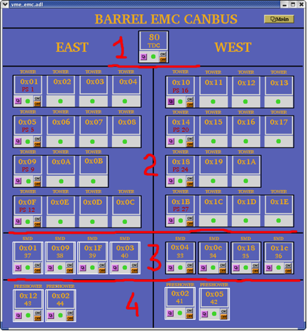
- Crate 80 TDC (Tower Data Collector and “Radstone boards”)
- Thirty crates for BTOW
- Eight crates for BSMD
- Four crates for BPSD
The BTOW crates are powered in groups of three or four from a single power supply (PS) units. The fragment below explains what you see.
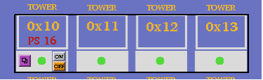
Tower crates 0x10, 0x11, 0x12, 0x13 are all powered from a single power supply: PS 16.
Thus, by clicking the On and Off buttons you will be switching On/Off all four crates and the communication with PMT boxes which are associated with them. (see details in Tower HV Control GUI description).
Sc5 and HDLC windows.
Two other terminal windows on “Terminal 0” are the so-called sc5, and HDLC windows.
These need to be open at all times. To open the sc3 terminal you will need to login as sysuser on sc5.starp.bnl.gov with password (check the control room copy of the manual).
From this sc5 terminal you run two programs. The first program is emc.tcl. If you need for some reason to restart “BEMC MAIN CONTROL” or “Barrel EMC Status” GUI you need to start emc.tcl: the alias for this is emc. To kill this program use alias kill_emc.
To open “Barrel EMC Canbus” GUI use alias emc_canbus_noscale.
If you need to reboot canbus then:
- open sc5 window
- telnet scserv 9040
- press “Ctrl” and “x” keys
- wait while canbus reboots (~5 minutes or so)
- press “Ctrl” and “]” keys
- quit telnet session
- close sc5 window
To open an HDLC window, first you need to open an sc3 window and then telnet scserv 9039.
To close telnet session you need to press “Ctrl” and “]”, and then quit from telnet.
You may be asked by experts on the phone to reset the radstone boards. This is why you need this window open. There are two radstone boards and to reset them type:
radstoneReset 0
and
radstoneReset 1
Terminal 1. “BEMC PMT Low Voltage Power Supply Slow Control”
There is a change in operation procedures for Run7 for PMT HV Low Voltage power supplies.
There are two low voltage power supply PL512 units which powers PMT bases.
PL512 with IP address 130.199.60.79 powers West side and PL512 with IP address 130.199.60.81 powers East side of the detector. A single power supply feeds thirty PMT boxes. The GUI for both PL512 should be open all time on one of the workspace on Terminal1. A screenshot below shows GUI at normal conditions. Both PL512 should be ON all the time, except the case when power cycling of the PMT bases is required.
There are two buttons to turn power On and Off, as usual, wait 30 sec. after turning power supply Off before you will turn it On again. To start GUI use aliases bemc_west and bemc_east on sc5.starp.bnl.gov

Terminal 2. “BTOW HV Control”

This is typical screen shot of the BTOW HV GUI during “Physics” running.

What is shown on this screen?
The top portion of the screen shows the status of the sixty BTOW PMT boxes. In this color scheme green means OK, yellow means bad, gray means masked out.
Buttons marked “PS1 ON” etc. allows to ramp slowly HV on the groups of the boxes. (PS1 ON will bring only boxes 32-39)
Buttons “EAST ON” and “WEST ON” allows to ramp up slowly entire east or west sides.
The fragment below explains what the numbers on this screen means.
![]()
Each green dot represent a single PMT box. Label 0x10 tells you that signals from PMTs in boxes 1 and 2 feed to BTOW crate 0x10, boxes 3 and 4 feed crate 0x11 etc. You will need to know this correspondence to quickly recover from HV trips.
Turning ON HV on BTOW from scratch.
1. BEMC PMT LV East and West should be ON.
2. EMC_HighVoltage.vi should be running.
3. Made a slow ramp on the West Side by pressing button “WEST ON”
4. Made a slow ramp on the East Side by pressing button “EAST ON”
Both steps 3 and 4 takes time, there is no audio or visual alarm to tell operators that HV was ramped – operators should observed progress in the window in the “Main Control” subpanel (see below).
Subpanel “Main Control”
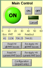
The HV on PMTs is usually ON during the Run. The two buttons on top are for turning the HV On and OFF on all PMT boxes. The most frequently used button on this subpanel is “Re-Apply HV all PMT Boxes” which is usually used to recover after HV trip. Sometimes you will need to “Re-Apply HV current PMT box” if the system does not set the HV on all boxes cleanly.
The scale 0-60 shows you a progress report. The small icons below this scale tells you what PMT box and PMT were addressed or readout.
Once you recover from a HV trip please pay attention to the small boxes labeled “Box”, “PMT”, and the speed at which the program reads the voltages on the PMTs. This will tell you which box has “Timeout” problems and which power supply will need to be power cycled.
Subpanel “PMTs In a Selected Box”
This subpanel shows you the status of the PMTs in a given PMT box.
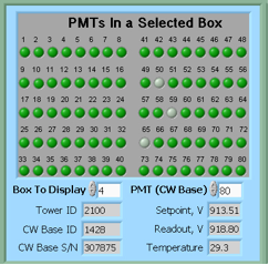
If you want to manually bring a single PMT box to the operational state by clicking on “Re-Apply HV current PMT box” on the Main Control subpanel you will need to specify which Box To Display on the panel first.
Subpanel “Alarm Control”
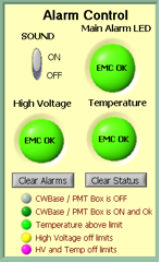
On the Alarm Control sub-panel the SOUND should be always ON, except for the case when you are recovering from a HV trip and wish to mute this annoying sound.
Shift personnel are asked to report HV trips in the shift log (type of trip, e.g. single box#, with or without timeout, massive trip, etc…)
Please don’t forget to switch this button back to the ON position after recovering from a trip.
The Main Alarm LED will switch color from green to red in case of an alarm.
HV trip with Timeout problem.
Typical situation – you hear a sound alarm indicating a HV trip. The auto-recovery program did not bring all PMT boxes to the operational state, e.g. some boxes will be shown in yellow. First thing to check for the presence of a “Timeout” problem.
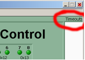
Look at the right upper corner of the GUI. If the field below “Timeouts” is blank then try to recover by re-applying HV to all PMT boxes if the number of bad boxes more then two. If only one or two boxes is yellow then you can try to re-apply HV to the current PMT box.
If only one or two PMT bases timed out and HV tripped try to recover using above procedure. It is possible that one or two PMT bases will timed without causing trips of HV, then just continue running and made a note in the shift log about timed out PMT bases, experts will take care of this problem during the day.
But it is also a chance that a single timed out PMT base will trip lots of other PMT. In this case this bad PMT should be masked out. The procedure to do this is simple and can be found at the end of this manual. However, this is an expert operation and should only be performed after consulting with a BEMC expert.
However, if the field below “Timeouts” is filled with numbers (these are PMTs addresses) then you have a Timeout problem. The procedure to recover is below:
- notify shift leader about this problem and tell him that it will take at least 20 min. to bring back BEMC for Physics running.
- Second, try to identify which PMT box has timeouts (usually it will be first box in yellow counting from 1 to 60). If you are not sure which box has the timeout problem then read all pmt boxes by clicking on corresponding button at the “Main Control” subpanel, and observe which box creates the problem. The box with timeout problem will be responding VERY slowly and will be clearly seen on the “Main Control” subpanel. At the same time, PMTs addresses will be appear in “Timeouts” white space to the right of the green control panel.
- As soon as you find the box with the timeout problem, click “Cancel” on the “Main Control” subpanel and then click “OFF” – you will need to turn HV OFF on all PMTs.
- Wait till HV is shut OFF (all PMT Boxes).
- From Terminal 1, power cycle correspondent PL512 (Off, wait 30 sec., On).
- Now turn ON HV on PMT boxes from the “Main Control” subpanel. It will take about 2 to 3 minutes first to send desired voltages to all PMTs and then read them back – if the HV is set correctly.
It is possible that during step (6) one of the BEMC PMT LV on the East or West side will trip. In this case cancel ramp (press “Cancel” button on the “Main Control” subpanel). Power cycle tripped BEMC PMT LV. Proceed with the slow ramp.
However, if during step (6) you still get a “Timeout” problem then you will need to:
- Call experts
-------------------- Changes for Run10 operation procedures ----------------------------
To reduce the number of HV trips and associated efficiency losses during data taking we changed functionality of the PMT HV program. Namely, the HV read back time interval was changed from 15 minutes to 9999 hours, because it was found that most of the HV trips were self induced during HV read back. As a result efficiency of data taking was improved for the price of “conscious operation”. You can‟t relay anymore on absence of the HV Trip alarm as an indicator that HV on all PMTs is at nominal values. Instead shift crew should monitor associated online plots during data taking to be sure that HV was not tripped. In particular, for Run 10, shift crew should watch two plots “ADC Eta Vs Phi” and “Tower ADC” under the “BEMC Shift” tab. Example of missed HV trip on one of the PMT box during recent data taking is shown below.
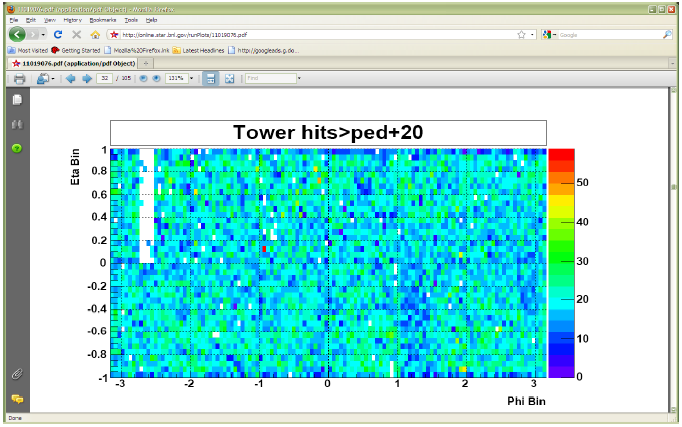
The white gap in the upper left corner shows absence of hits in BTOW due to HV trip in one of the BTOW PMT Box. It is easy to find out which box tripped by looking at second plot.
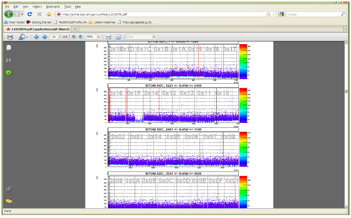
The gap with missing hits on the second subpanel for crate 0x15 will tell you that one of the PMT box 11 or 12 was tripped (correspondence between BTOW crates ID and PMT boxes is shown in the BTOW HV GUI see the picture at the beginning of this section).
What to do if shift crew will notify you of HV trip?
The fastest way to recover is to identify what box tripped and then try to recover only this PMT box. In some case it will be impossible to do this, because you will be needed to powercycle LV power supply for PMT HV system (timeout problems).
This is typical scenario:
1. Identify which PMT box(es) potentially tripped. (In the example above one PMT box 11 or 12 lost HV) to do that:
1.1 From the BTOW HV GUI form subpanel “PMTs In a Selected Box” select needed box in the “Box To Display” window.
1.2 From the BTOW HV GUI form subpanel “Main Control” press “Read HV current PMT Box”. (In the example above, detector operator found that Box 11 was OK after reading HV, but Box 12 had timeout problems).
1.3 Depending what will be result of (1.2) you may need to simply Re-Apply HV to current PMT box (no timeouts during step (1.2), or you will need to resolve timeout problem.
There are additional duties for detector operators when STAR is not taking data for long period of time for any reasons. We need to keep HV On on all PMTs at all time. This will assure stable gains on PMTs. If for some reasons PMTs will be Off for long time (few hours) then it will be difficult to assure that the PMTs gain will not drift once we turn HV On again. Typical situation is APEX days, when STAR is not taking data for 12 hours or so. To check that HV is on shift will be asked to take a short run 1k events using “bemcHTtest” configuration. TRG+DAQ+BTOW only. Once the data will be taken use a link from the run log browser to “LO Trigger”. Check page 6.
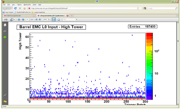
All trigger patches should have some hits. In case of the HV trips you will see blank spots.
Procedure to mask out single timeout PMT base.
Information you will need:
1. In which PMT box timeout PMT base is located
2. PMT (CW Base) to masked out.
In the timeout window the displayed number is CW Base ID this number need to be translated to PMT (CW Base).
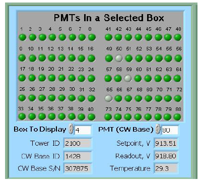
From this sub panel you can find out which PMT in the affected PMT box need to be masked out. Scroll thru the
PMT (CW Base) top right small window and read out at the same time CW Base ID in the second from the bottom left window. (As shown, PMT (CW Base) 80 correspond to CW Base ID 1428).
Now, click “Configuration (expert only)” button on the Main Control panel.
Another panel EMC_Configuration.vi will open.
From this panel click “CW Bases Configuration” button on the right bottom.
Another panel EMC_CWBasesConf.vi will open.
On this panel specify PMT BOX Number and then click on desired CW Base to be masked out. The color of the dot will change from bright green to pale green. Then click OK button.
Panel will close after that.
Click OK button on EMC_Configuration.vi panel, this panle will close after that.
To check that you masked out right CW Base, Re-Apply HV to current PMT box. Once HV will be re-applied you will see masked CW base will be in the gray color as shown in the picture above (Bases 50, 59, 65 were masked out in the PMT box 4).
Terminal 3. “BSMD HV Control”
Your login name is emc, your password is __________________________
This screenshot shows how the window on the terminal3 will look when the HV is Off on the BSMD modules. There should be two open windows. One is a LabView GUI and another is a telnet session SY1527 (CAEN HV Main Frame).
In normal operation it is a one click procedure to turn the HV On or OFF on the BSMD.
There is complete description of the BSMD HV program in a separate folder in this document.
Although, operation is very simple, attention should be made for audio alarms.
Do not mute the ALARM. Shift personnel are asked to report all BSMD trips in the shift log.
Terminal 0. “BPSD HV Control”
The BPSD (Barrel PreShower Detector) HV supplies are two Lecroy 1440 HV systems located on the second floor platform, racks 2C5. Each 1440 is commanded by a 1445A controller which communicates via the telnet server on the second floor of the platform (SCSERV [130.199.60.167]). The left supply uses port 9041 and the right supply uses port 9043.
The HV for BPRS should be On at all times.
From Run 10 for BPRS control we will be using new GUI. They will be open on one of the desktop on Terminal 0 (Beatrice.starp.bnl.gov). Usually detector operators no need to take any actions regarding BPRS HV unless specifically requested by experts. The screen shots of of the new GUIs shown below.
To start the GUI use type bemc_lecroy and bemc_lecroy2.


A Green LED indicators tells you that HV is On and at desired level.
You can open subpanel for any slot to read actual values of HV. The screen shot is shown below.

Please Ignore empty current charts – it is normal.
Sometime, BEMC PSD GUI can turn white, due to intermittent problems with LeCroy crate controller. Simply make a log in the shift log and continue normal operation. It is likely HV is still On and at desired level. Experts not need to be called right away in this case.
Easy Troubles:
BEMC Main Control seems to be frozen, e.g. program doesn’t respond to operators requests.
Probable reason: RadStone cards in a “funny state” and needs to be reset
From Terminal 1 try to:
- kill_emc
- soft reboot first “Ctrl” + “x” from HDLC terminal window.
- start emc and see if problem solved
If the problem is still there then:
- kill_emc
- Power Cycle Crate 80
- start emc and see if problem solved
If problem is still there call experts
PL512 Information (Run 11 configuration)
There are two PL512 power supplies which provides power to the BEMC PMT boxes. Both are located in the rack 2C2, second floor.
The top unit (IP address 130.199.60.79) serves West side of the detector. The bottom unit (IP address 130.199.60.81) serves East side of the detector. The connection scheme is shown below
PMT Boxes
West Side East Side
| 1-8 | 9-16 | 17-22 | 23-30 | 32-39 | 40-47 | 48-53 | 54-31 | |
| U 0,4,8 | 1,5,9 | 3,7,11 | 2,6,10 | 0,4,8 | 1,5,9 | 3,7,11 | 2,6,10 | |
| U 0,1,2,3 | +5 V | |||||||
| U 4,5,6,7 | -5 V | |||||||
| U 8,9,10,11 | +12 V |
Note , BEMC PMT Low Voltage Power Supply Slow Control channels enumerated from 1 to 12 in the Labview GUI.
Slow control for PL512 runs on EMC02, login as emc, alias PMT_LV.
You will need to specify IP address.
Configuration (Experts Only) password is ____________.
Log files will be created each time you will start PMT_LV in the directory
/home/emc/logs/
for example
/home/emc/logs/0703121259.txt (March 12, 2007, 12:59)
To restart PL512 epics applications.
Login to softioc1.starp.bnl.gov bemc/star_daq_sc
Look at procIDs
->screen –list
->screen –r xxxx.Bemc-west(east) xxxx is procID
->bemclvps2 > (ctrl A) to detach
exit to kill
->BEMC-West or East to restart
Experts control for PL512
If you need to adjust LV on PL512 you can do this using expert_bemc_west or (east).
These GUI has experts panel. Adjusting LV setting DO NOT try to slide the bars.
Instead click on it then on popup window you can simply type desired value.
Make sure you will close expert GUI and return to normal operational GUI once
you will finish adjustments.
A copy of this manual as a PDF document is available for download below.
Expert Contacts
Steve Trentalange (on site all run) e-mail: trent@physics.ucla.eduPhone: x1038 (BNL) or (323) 610-4724 (cell)
Oleg Tsai (on site all run) e-mail: tsai@physics.ucla.edu
Phone: x1038 (BNL)
SMD High Voltage Operation
Version 1.10 -- 04/25/06, O.D.TsaiOverview
The SMD detectors are a set of 120 proportional wire chambers located inside the EMC modules (one per module). The operating gas is Ar/CO2(90/10). The nominal operating voltage is +1430 V. As for any other gaseous detector, manipulation with high voltage should be performed with great care.A detailed description of the system is given in the Appendix.
SMD HV must be turned OFF before magnet ramp !
Standard Operation includes three steps.
Turn HV ON
Turn HV OFF
Log Defective Modules
To turn SMD HV ON the procedure is:
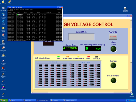
- On HOOSIER.STARP.BNL.GOV computer double click on the SMDHV icon on the Windows desktop. The 'SMD HIGH VOLTAGE CONTROL' window will open.
- On the SMD HIGH VOLTAGE CONTROL window click 'POWER' button.
- 'POWER' button will turn RED
- In no later than 90 + 150 + 300 sec in window 'Current Mode' you will see the message - "Physics Mode"
- All modules with high voltage on them will be shown in GREEN, LIGHT BROWN or YELLOW.
To turn HV OFF on SMD the procedure is:
- Click on the green 'POWER' button. Result:
- 'POWER' button will turn from green to BROWN
- after a 30 sec. or so small window will pop-up telling you that voltages an all channels reached zero.
- Click 'OK' on that small window to stop the program.
To Log Defective Modules
- Scroll down the window -- you will see three tables
- Log contents of the left table called 'Defect Module List' if any modules are presented here.
- Log contents of the right table called 'Modules tripped during Standby' (for example Run XXX #8 - 3 trips, Run XXX #54 - 1 trip)
- Close the 'SMD HIGH VOLTAGE CONTROL' window.
Detailed description of the SMD HV Program and associated hardware settings can be found in Appendix.
-------------------
Indicators to watch:
1. Interlock went RED
In case STAR global interlock went ON
- Interlock led will turn in RED
- the SMD HV program will turn OFF HV on all SMD channels and program will halt.
- Operator should close SMD HV Voltage control window.
Once STAR global interlock will be cleared follow usual procedure to power up SMD.
2. Server Timeout went RED or SMD HV Control program is frozen.
This is an unusual situation and SMD Expert Contacts should be alerted. The lost communication to SY1527 should not lead to immediate damages to the SMD chambers.
In case communication to the SY1527 is lost for some reason the 'SERVER TIMEOUT' led will turn RED. In case SMD HV Control program is frozen the 'Current Time' will not be updated.
Procedure to resolve problem is:
- Open terminal window on EMC01.STARP.BNL.GOV (monitor is on top of SMD HV Control PC)
- ping 130.199.60.50 -- observe that packets transmitted and received.
- If there are no communication with SY1527 (packets lost) -- Call one of the Expert Contacts!
- If communication is OK, then stop ping and type telnet 130.199.60.50 1527 -- You should see 'login window for CAEN SY1527 system'
- Press any key
- Login as 'admin' with password 'admin' -- you will see Main Menu window for SY1527
- From 'Main' chose 'Channels' by pressing 'Enter' -- you will see Channels menu window
- Verify HV is presented on channels (VMon)
Usually second terminal window is open on HOOSIER.STARP.BNL.GOV to monitor SY1527 HV power supply. If this window is not open use “putty” and open SY1527 session.
Now you can operate HV using this window, but if there is no emergency to turn HV OFF you should first try to restart SMD HV Control program.
Basic operations from that window are:
Turn HV OFF
Turn HV ON
Turn HV OFF
- press Tab key
- scroll to 'Groups' menu
- press 'Enter' to chose "Group Mode" --you will see highlighted column
- scroll to "Pw"
- press space bar -- you will see "Pw" will switched from On to Off and VMon will start to decrease.
- press Tab key
- select 'Group' mode
- scroll to IOSet
- type 5.0 (Current limit 5uA)
- scroll to Trip
- type 0.5 sec
- Verify that V0Set is 1430 V
- Scroll to Pw
- press Space bar -- you will see Pw will switch from OFF to ON and Status goes to Up. VMon will start to increase.
- Press Tab key
- reselect 'Group' mode
- Change I0Set and Trip for tripped channels
- Power them up - scroll to Pw, and press Space bar.
Appendix
Before you start:
"Be afraid, even paranoid, and that gives you a chance to catch bad effects in the early stages when they still do not matter"
--J. Va'vra (Wire Aging Conference)
Detailed information regarding SY1527 mainframe and A1733 HV distribution boards can be found at CAEN web page.
The SMD HV is supplied by the CAEN SY1527 HV system. The mainframe is located in rack 2C5 (Second Floor, Third Row, near the center). The HV cables run from modules to the SMD crates (15 cables per each crate). At each crate HV cables re-grounded on patch panels assuring same ground for HV and signals to be read. From SMD crates, the HV lines then run to the SY1527 system. There are 10 HV cards, 12 HV channels each (model A1733) inside the mainframe to supply high voltages to the SMD chambers. The parameters of the high voltage system controlled via Ethernet. The GUI based on LabView and CAEN OPC server.
Hardware settings are:
HV Hardware limit set to +1500 V on each of A1733 cards.
HV Software limit (SVMax) set to +1450 V for each channel.
Communications settings for SY1527 are:
IP           130.199.60.50
Net Mask     255.255.254.0
Gateway      0.0.0.0
User name    Admin
Password Admin(from top to bottom, HV is Off)
LED
Chk Pass On
Toggle Switch 'Loc enable' On
Ch Status 'NIM' On
Interlock 'Open'
Master On
+48 V On
+5 V On
+12 V On
-12 V On
Main On
Each A1733 card should have 50 Ohm Lemo 00 terminator to enable HV.
Description of SMD High Voltage Control program.
All SMD HV software is installed on EMCSC.STARP.BNL.GOV in folder C:/SY1527
The SMD HV Control provides one button operation of the HV system for the SMD. There are three main functions Power On, Physics Mode, Power Off. There are two configuration files Conf.txt and Conf2.txt which defines ramp up speed and trip settings for different mode of operation.
The nominal settings for Power On are (C:/SY1527/Conf.txt):
V0 1430 V
I0Set 5 uA
Trip 0.5 s
Ramp Down 50 V/sec
Ramp Up 20 V/sec
All channels are allowed to be ramp up in three consecutive attempts. If the first attempt (90 sec) for given channel lead to trip then ramp up speed will be set to 10 V/sec and second attempt (150 sec) will be performed. If second attempt will lead to trip then ramp up speed will be set to 7 V/sec and third attempt (300 sec) will be made. If all three attempt led to trip the program disconnect that particular channel from HV (corresponding led on main panel will turn in RED).
In no later then 90 + 150 + 300 seconds program will change parameters of I0Set and Trip form 5 uA and 0.5 sec to 1.6 uA and 0.1 sec and will switch to the Physics Mode.
The nominal settings for Physics Mode are (C:/SY1527/Conf2.txt)
V0 1430 V
I0Set 1.6 uA
Trip 0.1 s
Ramp Down 50 V/sec
Ramp Up 20 V/sec
Channels allowed to trip no more then 6 times during the Physics Mode. If channel will trip then I0Set and Trip for that particular channel will be set to 5 uA and 0.5 sec and program will try to bring that channel up. On front panel Alarm Status will turn in RED, corresponded message will pop up in 'Current Mode' window, and corresponded to that channel LED will turn in YELLOW or RED. Once voltage reach 90% of nominal all indicators will turn to normal status. Usually it takes about 15 seconds to bring channel back to normal. At the bottom of the screen the right table with modules that tripped during the Physics Mode will be updated. If some channel will trip more than 6 times that channel will be HV disabled by the program and corresponded led will turn RED. The left table on the bottom of the screen will be updated. Such cases should be treated by experts only later on.
All SMD channels during the Physics Mode is under the monitoring. Each 3 seconds or so, the values of Voltage, Current and time are logged in files XX_YY_ZZ_P.txt in C:/SY1527/Log, where XX - current month, YY - current day, ZZ - current year, and P is V for Voltages and I for Currents. The current time saved in seconds. The macro C:/SY1527/smdhv.C plots bad channels history and fills histograms for all other channels.
Turn Off is trivial and no need explanations.
The meaning of the LED on main panel are:
Green – channel is at nominal HV, current < 1 uA
Brown – channel is at nominal HV, 1 uA < current < 5 uA
Yellow – the HV is < 50% of nominal
Red - channel was disconnected due trips during ramp up or physics modes.
Black - channel disabled by user (Conf.txt, Conf2.txt)
It is important to monitor channels with high current (“Brown”), as well as channels that shows high number of trips during the operation. Note: some channels (54 for example) probably has a leakage on external HV distribution board and believed to be OK in terms of discharges on anode wires as was verified during summer shutdown. The other might develop sparking during the run or might have intermittent problems (#8 for example). If problems with sparking will be detected at early stages then those channels might be cured by experts during the run, without of loss of entire chamber as it was happened during the first two years of operation.
The C:/SY1527/ReadSingleChannel.vi allows to monitor single channel. You may overwrite nominal parameters of HV for any channel using that program (it is not desired to do that). This program can run in parallel with the Main SMD HV Control program. The operation is trivial, specify 'Channel to monitor' and click on 'Update Channel'. If you wish to overwrite some parameters (see above) then fill properly VOSet etc. icons and click on Update Write.
Important! Known bug. Before you start you better to fill all parameters, if you do not do that and stop the program later on the parameters will be overwritten with whatever it was in those windows, i.e. if V0Set was 0 then you will power Off the channel.
In some cases it is easy to monitor channels by looking at front panel of the SY1527 mainframe. The image of this panel can be
obtained by opening telnet session (telnet 130.199.60.50 1527) on EMC01.STARP.BNL.GOV.
All three programs can run in parallel.
-----Experts to be called day or night no matter what---
1. The operation crew lost communication with SY1527
2. Any accidental cases (large number (>5) of SMD channels
suddenly disconnected from HV during the run)
For experts only!
What to do with bad modules?
1. If anode wire were found broken then disable channel by changing 1430 to 0 in both configuration files. That should help to avoid confusions of detector operators.
2. If anode wires are OK, and module trips frequently during first half an hour after power Up then it is advised to set HV on that particular channel to lower value (-100V, -200V from nominal etc…) and observe the behavior of the chamber (ReadSingleChannel.vi). In some cases after a few hours module can be bring back to normal operation.
3. If step 2 did not help, then wait till scheduled access and try to cure chamber by applying reverse polarity HV. Important, you can do that using good HV power supply (fast trip protection, with current limit 5uA), or by using something like ‘Bertran’ with external microammeter and balance resistor of no less then 10 MOhm, only! In any case you need to observe the current while gradually increase HV. In no case ‘Bertarn’ like power supply might be left unattended during the cure procedure. It is not advised to apply more then -1000 V. In some cases curing procedure might be fast (one hour or so). In others it might take much longer (24 hours and more) to bring module back to operation. In any case I would request to talk with me.
4. The SMDHV is also installed on EMCSC.STARP.BNL.GOV and can be run from there, although that will for sure affect BTOW HV, be advised.
LOG:
Version 1.00 was written 11/12/03
Version 1.10 corrected 04/25/06
A copy of this manual as a Word document is available for download below.