FGT. . . . . . . . . H A R D W A R E -- D E T E C T O R
- FGT foil
- FGT disk
- FGT strip design, gerber screen dumps, 2010-12-20
- strip 2 APV mapping, R-plane
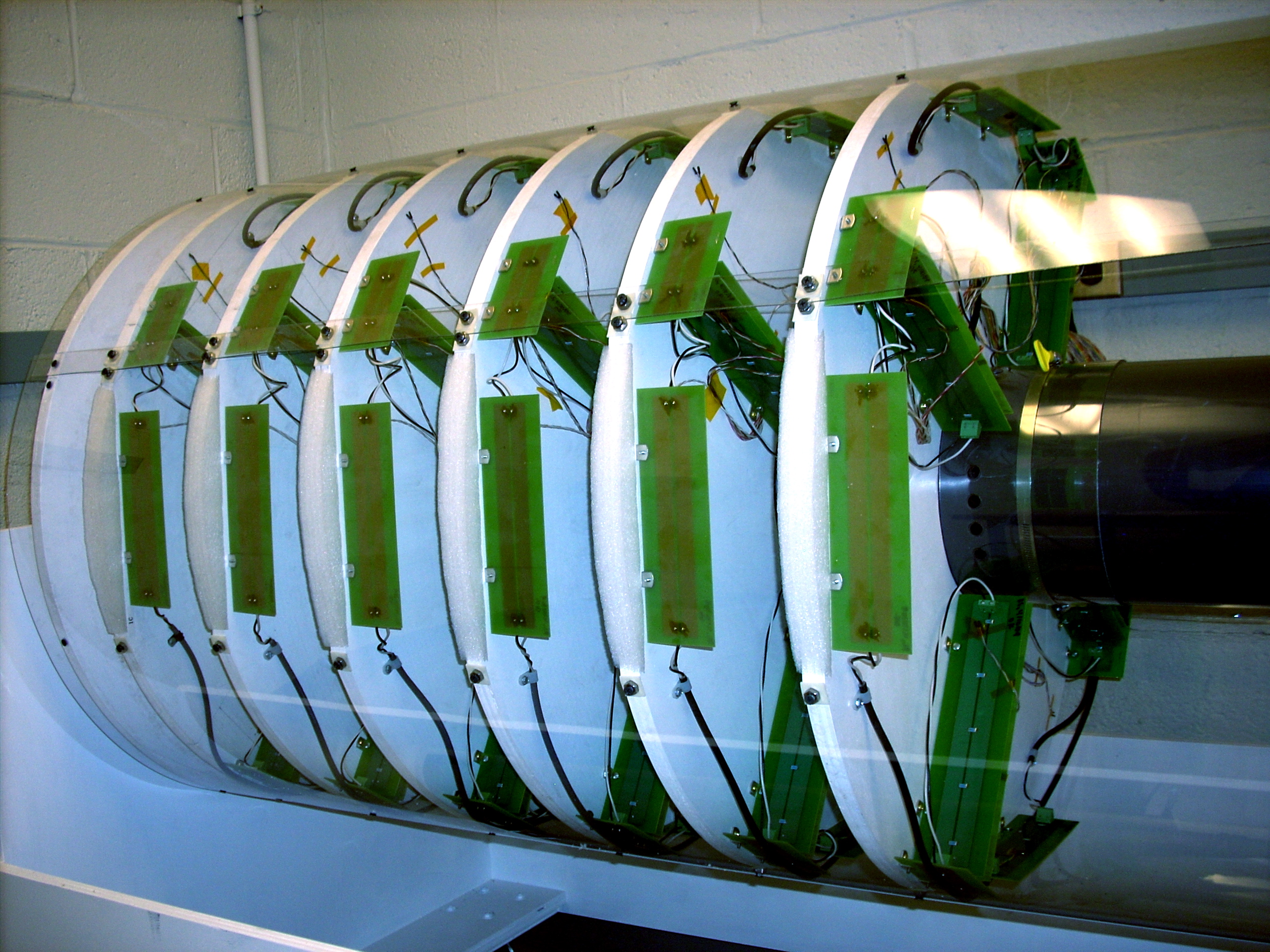
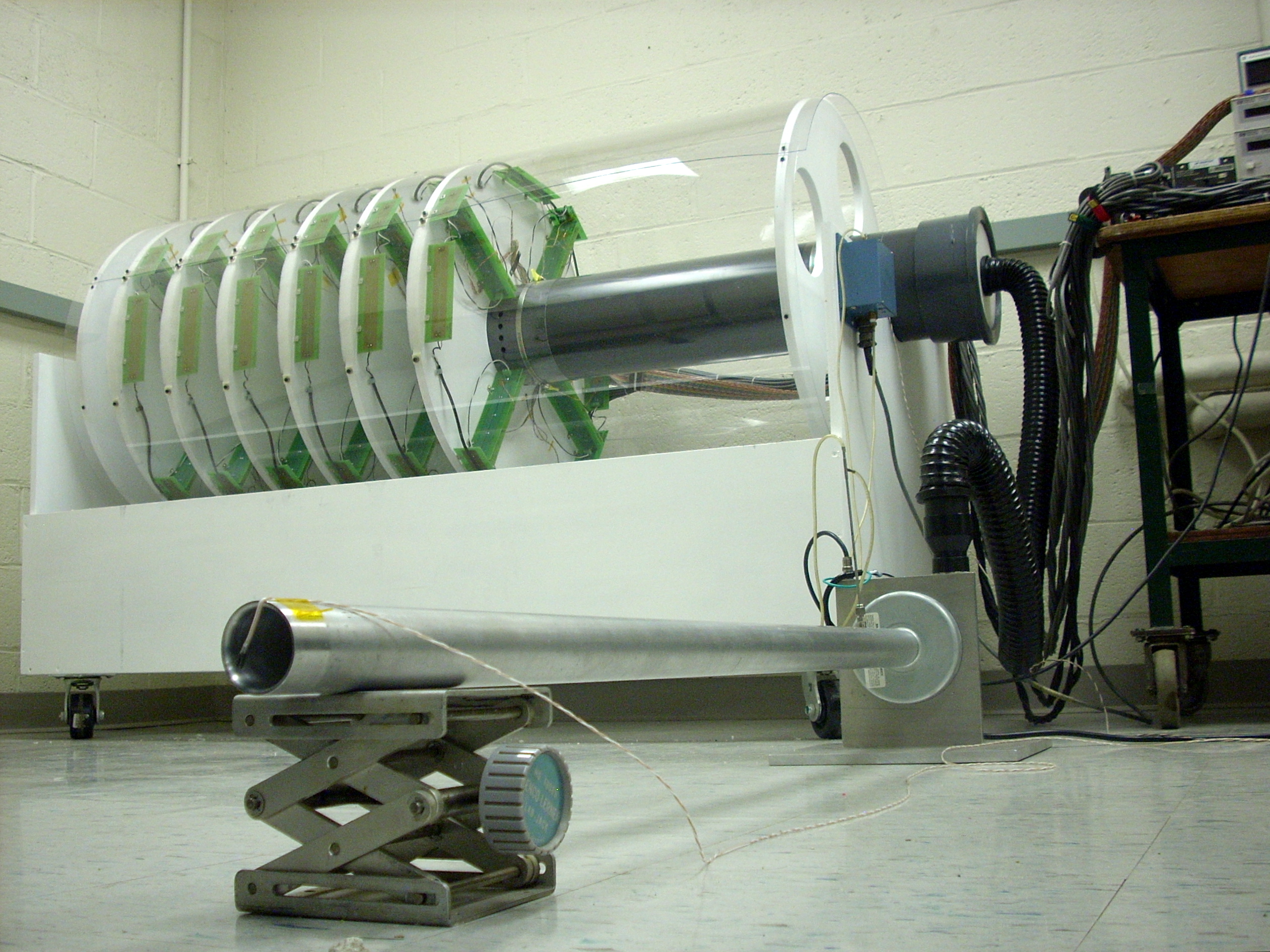
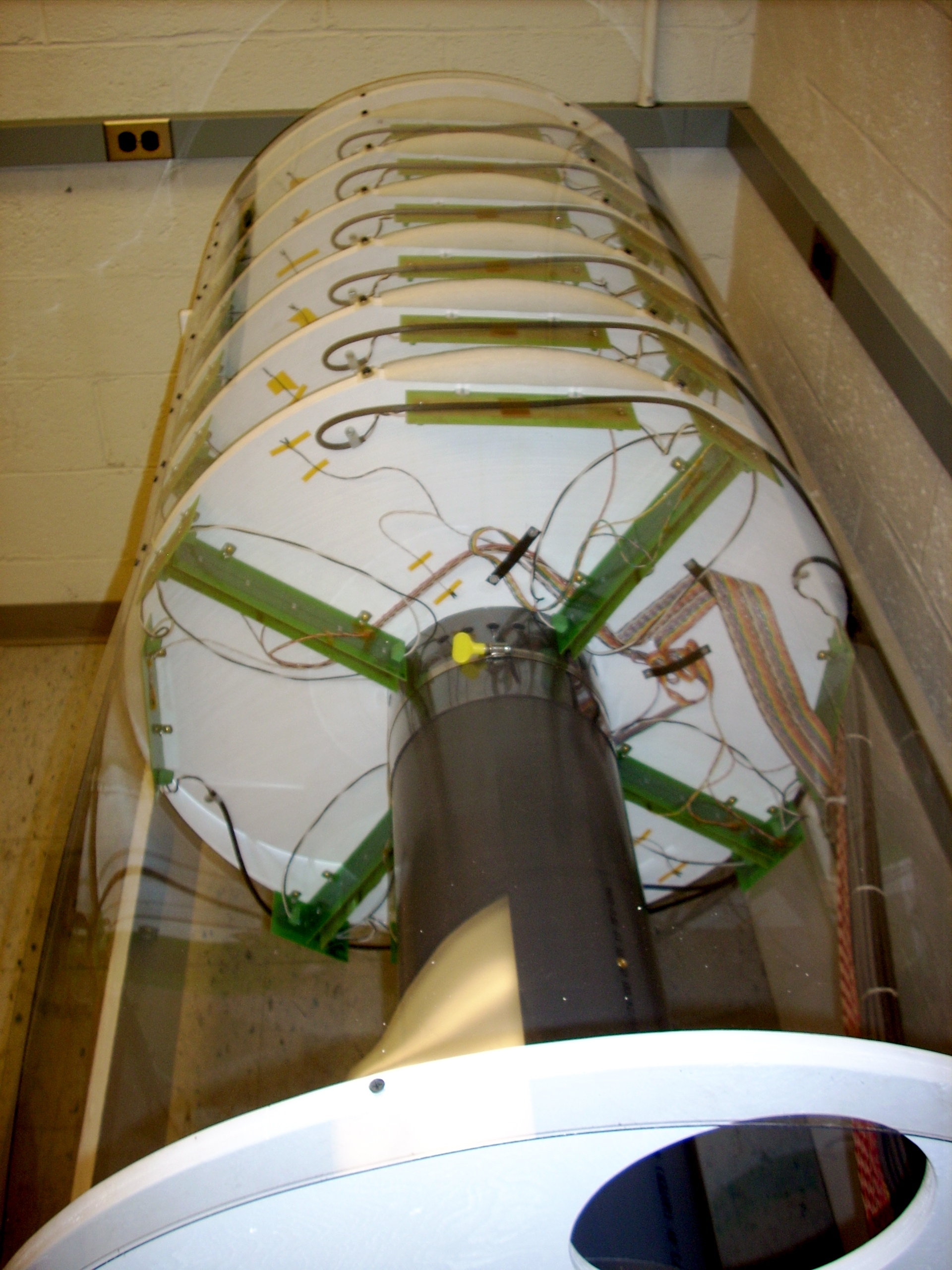
- 6-disk assembly
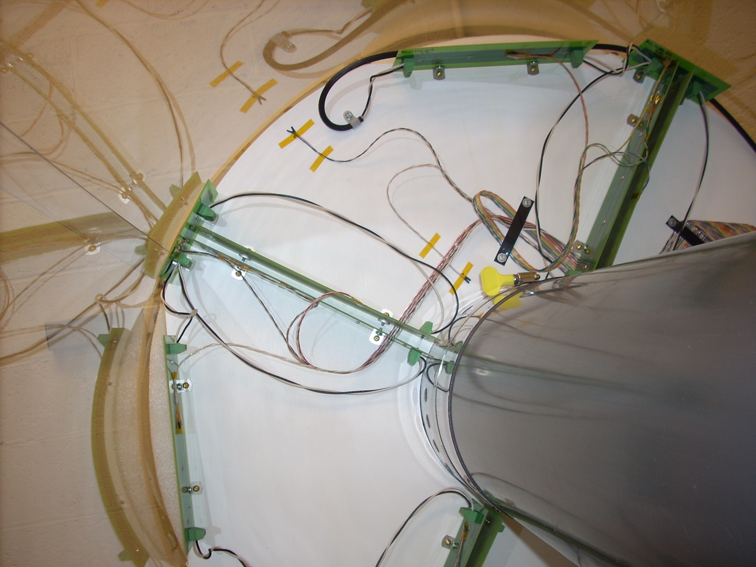
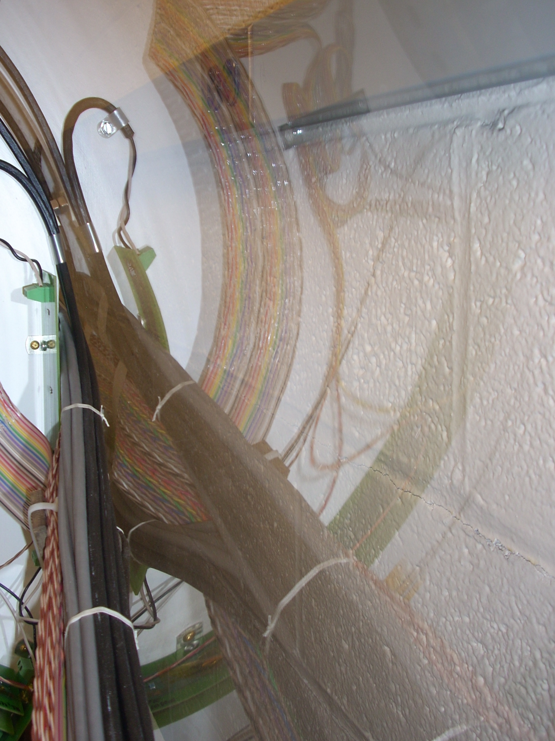
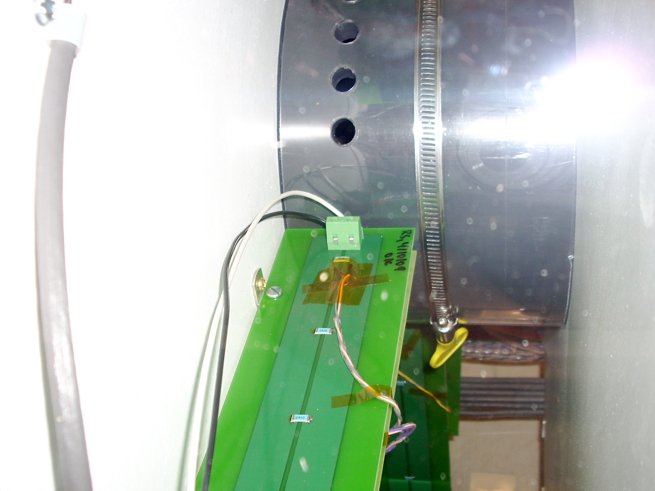
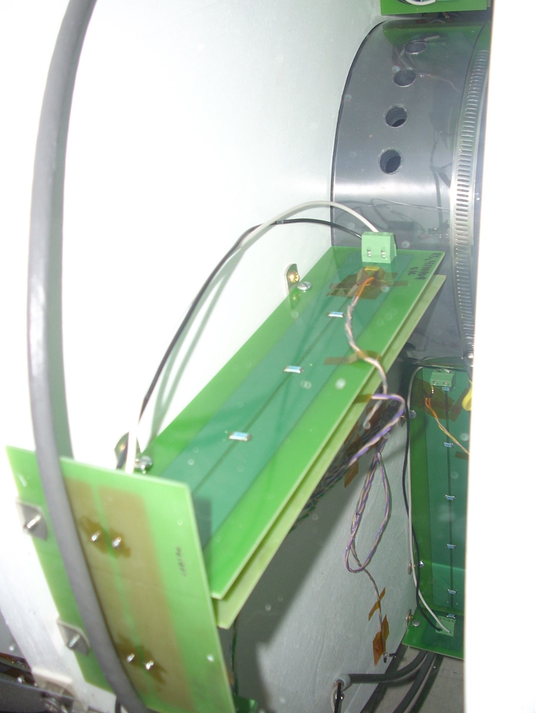
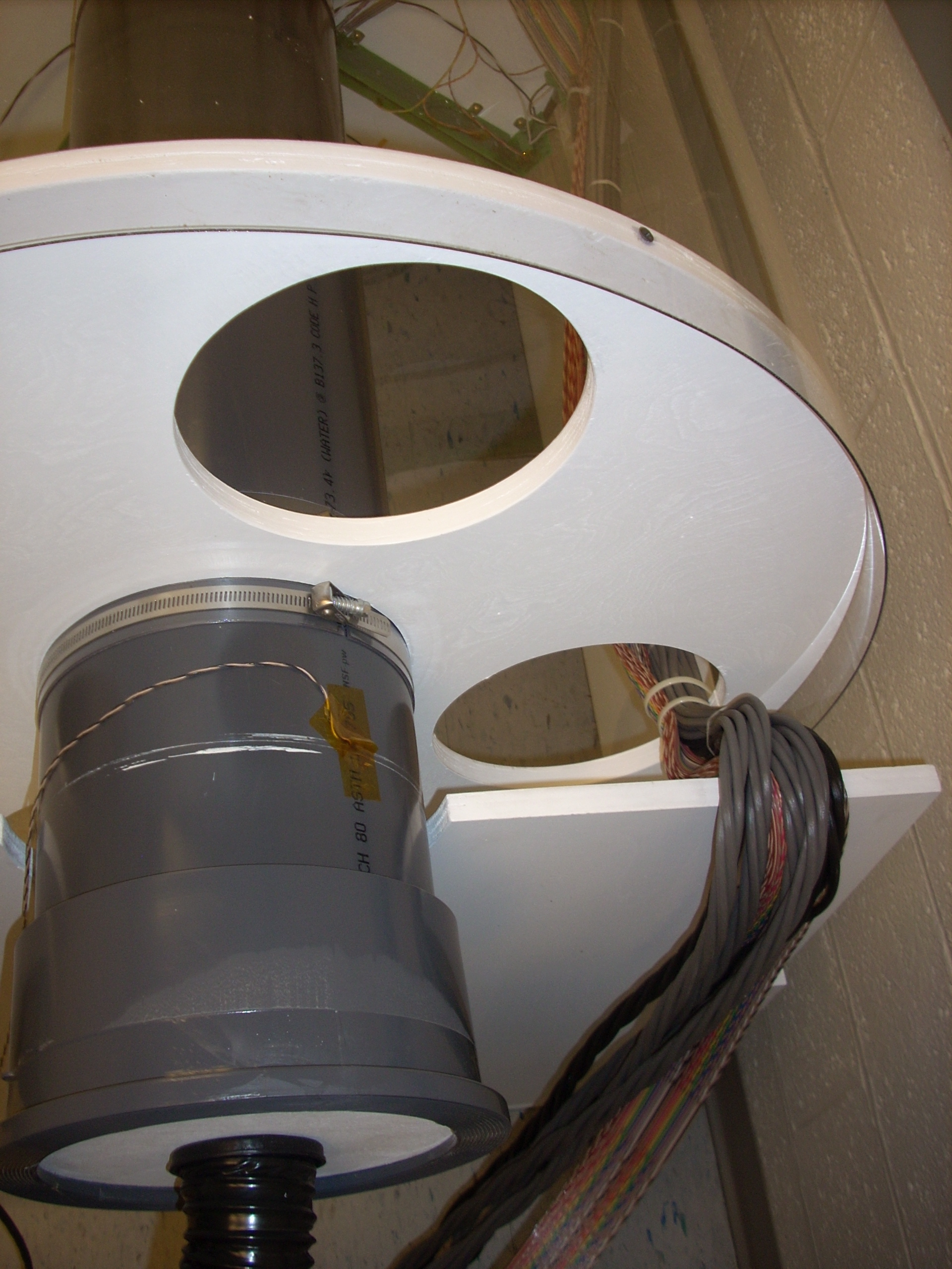
- integration w/ STAR
date revision format component March 2008 ? revXXX? PDF west support cylinder March 2008 ? 4.0 ? PDF mounting of FGT foil quadrant
Electrostatic Calculations for West Support Cone
Hi all;
I've put some results from the latest electrostatic
calculations for the WSC at:
http://hepwww.physics.yale.edu/star/upgrades/WSC-D.ppt
http://hepwww.physics.yale.edu/star/upgrades/WSC-D.pdf
The first page shows the key elements of the model and
the changes from previous versions:
- All edges of the WSC are radius'ed with 2 cm
- The resistor chain is now from Jan's "good" drawing
- The resistior chain is not rotated 16 degrees from
top - this makes it easier to navigate the "region
of interest" for studying the high field region.
This page also shows the orientation of the coordinate
system.
The next six pages are pairs of field plots. Each pair
shows the magnitude of the electric field in a slice
normal to the Z (X, Y) axis. The slice is taken at
the location of the maximum field. The second of each
pair of plots is just a zoom in on the hot spot.
The last plot shows that maximum field in an X-slice
vs. X. If people have questions or suggestions, we
can discuss this in tomorrow's meeting.
Best regards,
Dick Majka
Electrostatic Calculations for West Support Cone
Calculations from 24-July-2008 with "corrected" resistor chain geometry.
Rusults compared using 1mm mesh and 2mm mesh
FGT Thermo-model D=16cm
Photo documentation of Thermo-model A of FGT, 2009-08-10
FGT Thermo-model D=16cm
Photo documentation of Thermo-model A of FGT, 2009-08-10
Consistent with measurements posted by James on 2009-07-28.
Gas system assembly drawings
Please note the following attachments:
- Gas system assembly drawings as of 5 February 2011.
- Gas system assembly drawings for cosmic ray tests in clean room at BNL: Safety review on 29 April 2011.
- Photo: front of gas system control panel for cosmic ray test - as of 10 May 2011.
- Photo: rear of gas system control panel for cosmic ray test - as of 10 May 2011
Donald Koetke
donald.koetke@valpo.edu
drawings for the FGT full-size prototype frames, HV layer, and GEM foils, August 11, 2008
These are the current drawings for the FGT full-size prototype frames, HV layer, and GEM foils.
Cheers,
Douglas
general routing for the top and bottom GEM, August 16,
these Gerber files show the general routing for the top and bottom GEM foil layers plus a representative sample of the GEM foil holes showing the spacing from frame edges and segment boundaries.