Other FC short distortion measurements
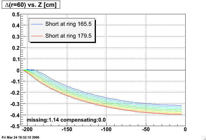
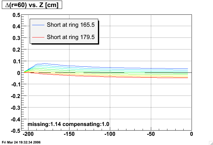
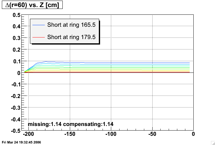
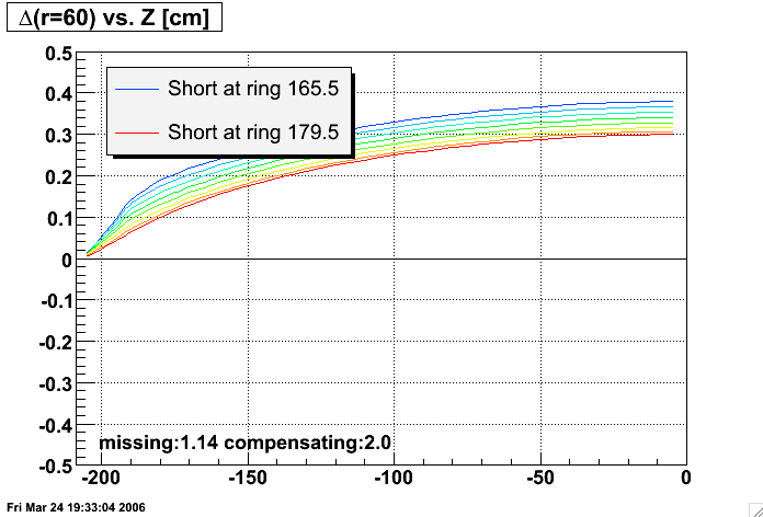
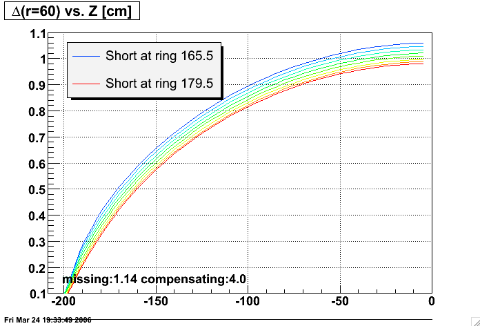
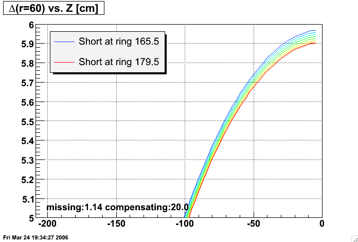
I considered the possibility that other measurements might help isolate the location of the short in the TPC. So, using the Modeled distortions, I modeled the effects of adding even more compensating resistance to the end of the IFC east resistor chain. Below are the results for shorts located at ring 165.5 (between rings 165 and 166), 167.5, 169.5, ..., 179.5 as indicated for the colored curves. All plots use a 1.0cm range on the vertical scale so that they can be easily compared. I had hoped that one resistance choice or another would cause more separation between the curves, giving better resolving power between different short locations. But this dependence is small, and actually seems to decrease a little with increased compensating resistance. Remember also that the last laser is at Z of about -173cm.Also perhaps worth noting is that the 1.0MOhm compensating resistor probably helps reduce the distortions even more than an exact 1.14MOhm would. The latter causes the distortions not to change between the short location and the central membrane, but the former actually causes the distortion to re-correct the damage done between the short location and the endcap!
| Compensating resistance [MOhms] |
Distortion on first padrow vs. Z |
|---|---|
| 0.0 |
 |
| 1.0 |
 |
| 1.14 |
 |
| 2.0 |
 |
| 4.0 |
 |
| 20.0 |
 |
Gene Van Buren
gene@bnl.gov