TPC Calibrations
TPC Calibration & Data-Readiness Tasks:
Notes:
* "Run", with a capital 'R', refers to a year's Run period, e.g. Run 10)
* Not all people who have worked on various tasks are listed as they were recalled only from (faulty) memory and only primary persons are shown. Corrections and additions are welcome.
- You do not have access to view this node
- Should be done each time the TPC may be moved (e.g. STAR is rolled out and back into the WAH) (not done in years)
- Must be done before magnet endcaps are moved in
- Past workers: J. Castillo (Runs 3,4), E. Hjort (Runs 5,6), Y. Fisyak (Run 14)
- TPC Pad Pedestals
- Necessary for online cluster finding and zero suppression
- Uses turned down anode HV
- Performed by DAQ group frequently during Run
- Past workers: A. Ljubicic
- TPC Pad Relative Gains & Relative T0s
- Necessary for online cluster finding and zero suppression
- Uses pulsers
- Performed by DAQ group occasionally during Run
- Past workers: A. Ljubicic
- TPC Dead RDOs
- Influences track reconstruction
- Monitored by DAQ
- Past workers: A. Ljubicic
- You do not have access to view this node
- Monitor continually during Run
- Currently calibrated from laser runs and uploaded to the DB automatically
- Past workers: J. Castillo (Runs 3,4), E. Hjort (Runs 5,6), A. Rose (Run 7), V. Dzhordzhadze (Run 8), S. Shi (Run 9), M. Naglis (Run 10), G. Van Buren (Run 12)
- TPC Anode HV
- Trips should be recorded to avoid during reconstruction
- Dead regions may influence track reconstruction
- Reduced voltage will influence dE/dx
- Dead/reduced voltage near inner/outer boundary will affect GridLeak
- Past workers: G. Van Buren (Run 9)
- TPC Floating Gated Grid Wires
- Wires no longer connected to voltage cause minor GridLeak-like distortions at one GG polarity
- Currently known to be two wires in Sector 3 (seen in reversed polarity), and two wires in sector 8 (corrected with reversed polarity)
- Past workers: G. Van Buren (Run 5)
- TPC T0s
- Potentially: global, sector, padrow
- Could be different for different triggers
- Once per Run
- Past workers: J. Castillo (Runs 3,4), Eric Hjort (Runs 5,6), G. Webb (Run 9), M. Naglis (Runs 10,11,12), Y. Fisyak (Run 14)
- You do not have access to view this node
- Dependence of reconstructed time on pulse height seen only in Run 9 so far (un-shaped pulses)
- Past workers: G. Van Buren (Run 9)
- You do not have access to view this node
- Known shorts can be automatically monitored and uploaded to the DB during Run
- New shorts need determination of location and magnitude, and may require low luminosity data
- Past workers: G. Van Buren (Runs 4,5,6,7,8,9,10)
- You do not have access to view this node
- Two parts: Inner/Outer Alignment, and Super-Sector Alignment
- Requires low luminosity data
- In recent years, done at least once per Run, and per magnetic field setting (perhaps not necessary)
- Past workers: B. Choi (Run 1), H. Qiu (Run 7), G. Van Buren (Run 8), G. Webb (Run 9), L. Na (Run 10), Y. Fisyak (Run 14)
- TPC Clocking (Rotation of east half with respect to west)
- Best done with low luminosity data
- Calibration believed to be infrequently needed (not done in years)
- Past workers: J. Castillo (Runs 3,4), Y. Fisyak (Run 14)
- TPC IFC Shift
- TPC Twist (ExB) (Fine Global Alignment)
- Best done with low luminosity data
- At least once per Run, and per magnetic field setting
- Past workers: J. Castillo (Runs 3,4), E. Hjort (Runs 5,6), A. Rose (Runs 7,8,9), Z. Ahammed (Run 10), R. Negrao (Run 11), M. Naglis (Run 12), J. Campbell (Runs 13,14), Y. Fisyak (Run 14)
- You do not have access to view this node
- Done with low (no) luminosity data from known distortions
- Done once (but could benefit from checking again)
- Past workers: G. Van Buren (Run 4), M. Mustafa (Run 4 repeated)
- You do not have access to view this node
- At least once per Run, and per beam energy & species, and per magnetic field setting
- Past workers: J. Dunlop (Runs 1,2), G. Van Buren (Runs 4,5,6,7,8-dAu,12-pp500), H. Qiu (Run 8-pp), J. Seele (Run 9-pp500), G. Webb (Run 9-pp200), J. Zhao (Run 10), A. Davila (Runs 11,12-UU192,pp200,pp500), D. Garand (Run 12-CuAu200), M Vanderbroucke (Run 13), M. Posik (Run 12-UU192 with new alignment), P. Federic (Run 12-CuAu200 R&D)
- You do not have access to view this node
- Once per Run, and per beam energy & species, and per magnetic field setting
- Past workers: Y. Fisyak (Runs 1,2,3,4,5,6,7,9), P. Fachini (Run 8), L. Xue (Run 10), Y. Guo (Run 11), M. Skoby (Runs 9-pp200,12-pp200,pp500), R. Haque (Run 12-UU192,CuAu200)
- TPC Hit Errors
- Once per Run, and per beam energy & species, and per magnetic field setting
- Past workers: V. Perev (Runs 5,7,9), M. Naglis (Runs 9-pp200,10,11,12-UU193), R. Witt (Run 12-pp200,pp500, Run13)
- TPC Padrow 13 and Padrow 40 static distortions
- Once ever
- Past workers: Bum Choi (Run 1), J. Thomas (Runs 1,18,19), G. Van Buren (Runs 18,19) I. Chakaberia (Runs 18,190
To better understand what is the effect of distortions on momentum measurements in the TPC, the attached sagitta.pdf file shows the relationship between track sagitta and its transverse momentum.
Miscellaneous TPC calibration notes
The log file for automated drift velocity calculations is at ~starreco/AutoCalib.log.Log files for fast offline production are at /star/rcf/prodlog/dev/log/daq.
The CVS area for TPC calibration related scripts, macros, etc., is StRoot/macros/calib.
Padrow 13 and Padrow 40 static distortions
These two distortion corrections focus on static non-uniformities in the electric field in the gating grid region of the TPC, radially between the inner and outer sectors. This region has an absence of gating grid wires where the subsector structures meet, allowing some bending of the equipotential lines, creating radial electric field components. In both cases, the region of distorted fields is quite localized near the endcap and only over a small radial extent, but this then distorts all drifting electrons (essentially from all drift distances equally) in that small radial region, affecting signal only for a few padrows on each side of the inner/outer boundary.Padrow 13 Distortion
For the original TPC structure, the was simply nothing in the gap between the inner and outer sectors. More about the gap structure can be learned by looking some of the GridLeak documentation (which is different in that it is dynamic with the ionization in the TPC. This static distortion was observed in the early operation of STAR when luminosities were low, well before the GridLeak distortion was ever observed. It was modeled as an offset potential on a small strip of the TPC drift field boundary, with the offset equal to a scale factor times the gating grid voltage, where the scale factor was calibrated from fits to the data. Below are the related distortion correction maps.
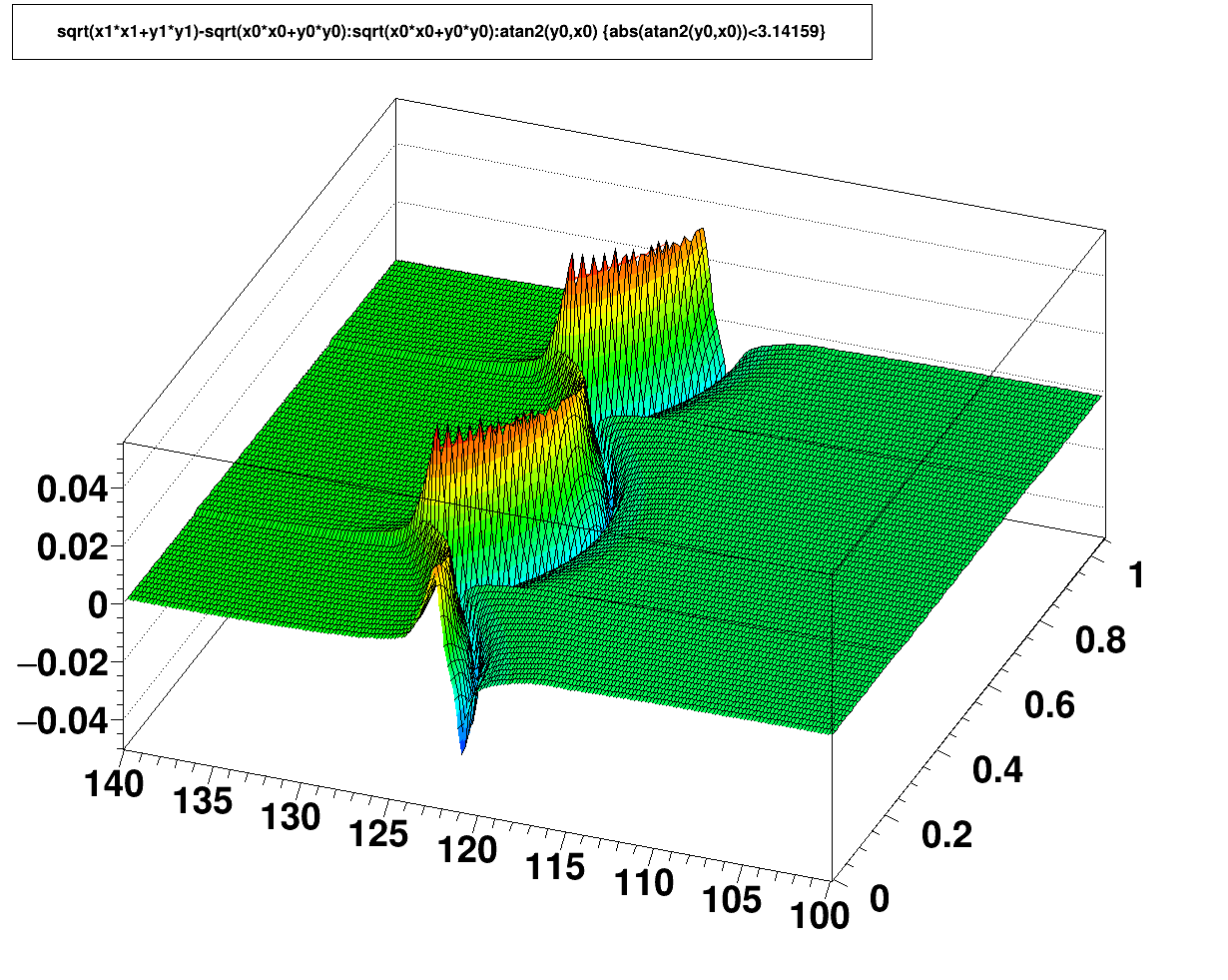
Padrow 40 Distortion
With the iTPC sectors, a wall was placed at the outer edge of the new inner sectors with conductive stripes on it to express potentials primarily to suppress the GridLeak distortion. It was understood that this would modify the static distortion, and in the maps below it is apparent that the static distortions became a few times larger with the wall, but in both cases only at the level of ~100 μm or less at the outermost padrow of the inner sectors. It is also worth noting that the sign of the distortion flipped with respect to Padrow 13.
This distortion correction is determined from the sum of 3 maps that represent the distortion contributions from (1) the wall's grounded structure, (2) the potential at the wall's tip [nominally -115 V], and (3) the potential on the wall's outer side [nominally -450 V]. Plots on this page were made using the nominal potentials.
Distortion correction maps:
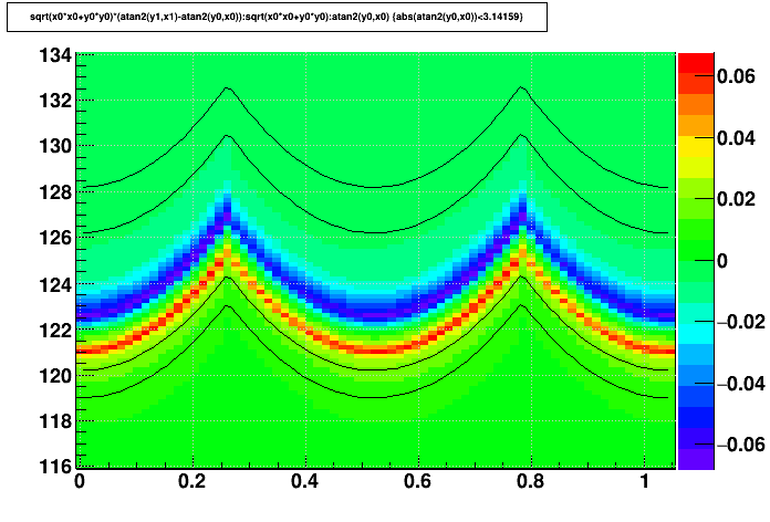
The maps are essentially uniform in z, so the maps shown below focus only on the radial and azimuthal dependencies. Further, there is no distortion more than a few centimeters away from the inner/outer boundaries, and there is essentially a 12-fold symmetry azimuthally (though this is not strictly true if different wall voltages are used on different iTPC sectors), so the maps zoom in on a limited region of r and φ to offer a better view of the fine details. Also, the inner and outer edges of the nearest padrows are shown as thin black lines on some plots to help understand their proximity to the distortions.
Open each map in a new web browser tab or window to see higher resolution. Units are [cm] and [radian].
| Δ(r-φ) vs. r and φ | Δ(r) vs. r and φ | |
|---|---|---|
| Padrow 13 | 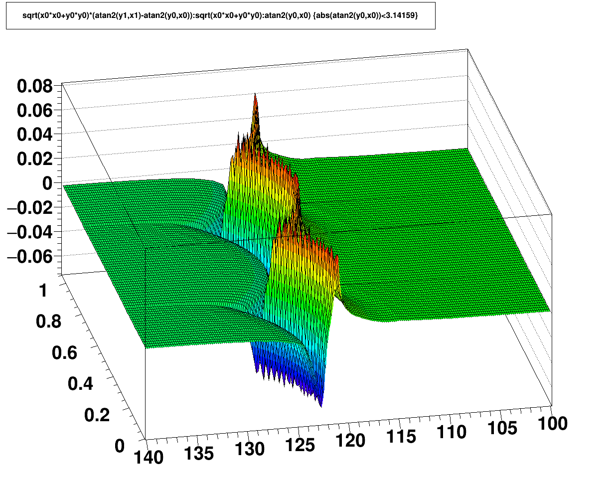 |
 |
| Padrow 13 lines indicating locations of rows 13 and 14 |
 |
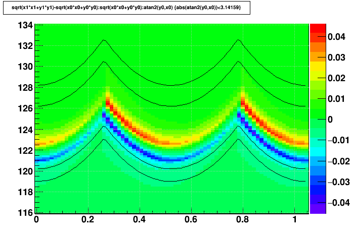 |
| Padrow 40 |  |
 |
| Padrow 40 lines indicating locations of rows 40 and 41 |
 |
 |
-Gene
RunXI dE/dx calibration recipe
This is a recipe of RunXI dEdx calibration by Yi Guo.
TPC Hit Errors
TPC T0s
Global T0:- Instructions (as of 2012, calibrated along with Twist)
- Run 10 calibration
- Run 12 calibration
Twist (ExB) Distortion
ExB (twist) calibration procedure
In 2012, the procedure documentation was updated, including global T0 calibration:
Below are the older instructions.________________
The procedure here is basically to calculate two beamlines using only west tpc data and only east tpc data independently and then adjust the XTWIST and YTWIST parameters so that the east and west beamlines meet at z=0. The calibration needs to be done every run for each B field configuration. The obtained parameters are stored in the tpcGlobalPosition table with four different flavors: FullmagFNegative, FullMagFPositive, HalfMagFPositive and HalfMagFNegative.
To calculate the beamline intercept the refitting code (originally written by Jamie Dunlop) is used. An older evr-based version used by Javier Castillo for the 2005 heavy ion run can be found at ~startpc/tpcwrkExB_2005, and a version used for the 2006 pp run that uses the minuit vertex finder can be found at ~hjort/tpcwrkExB_2006. Note that for the evr-based version the value of the B field is hard coded at line 578 of pams/global/evr/evr_am.F. All macros referred to below can be found under both of the tpcwrkExB_200X directories referred to above, and some of them under ~hjort have been extensively rewritten.
Step-by-step outline of the procedure:
1. If using evr set the correct B field and compile.
2. Use the "make_runs.pl" script to prepare your dataset. It will create links to fast offline event.root files in your runsXXX subdirectory (create it first, along with outdirXXX). The script will look for files that were previously processed in the outdirXXX file and skip over them.
3. Use the "submit.pl" script to submit your jobs. It has advanced options but the standard usage is "submit.pl rc runsXXX outdirXXX" where "rc" indicates to use the code for reconstructed real events. The jobs will create .refitter.root files in your ourdirXXX subdirectory.
4. Next you create a file that lists all of the .refitter.root files. A command something like this should do it: "ls outdirFF6094 | grep refitter | awk '{print "outdirFF6094/" $1}' > outdirFF6094/root.files"
5. Next you run the make_res.C macro (in StRoot/macros). Note that the input and output files are hard coded in this macro. This will create a histos.root file.
6. Finally you run plot_vtx.C (in StRoot/macros) which will create plots showing your beamline intercepts. Note that under ~hjort/tpcwrkExB_2006 there is also a macro called plot_diff.C which can be used to measure the offset between the east/west beams more directly (useful for pp where data isn't as good).
Once you have made a good measurement of the offsets an iterative procedure is used to find the XTWIST and YTWIST that will make the offset zero:
7. In StRoot/StDbUtilities/StMagUtilities.cxx change the XTWIST and YTWIST parameters to what was used to process the files you analyzed in steps 1-6, and then compile.
8. Run the macro fitDCA2new.C (in StRoot/macros). Jim Thomas produces this macro and you might want to consult with him to see if he has a newer, better version. An up-to-date version as of early 2006 is under ~hjort/tpcwrkExB_2006. When you run this macro it will first ask for a B field and the correction mode, which is 0x20 for this correction. Then it will ask for pt, rapidity, charge and Z0 position. Only Z0 position is really important for our purposes here and typical values to use would be "1.0 0.1 1 0.001". The code will then report the VertexX and VertexY coordinates, which we will call VertexX0 and VertexY0 in the following steps.
9. If we now take VertexX0 and VertexY0 and our measured beamline offsets we can calculate the values for VertexX and VertexY that we want to obtain when we run fitDCA2new.C - call them VertexX_target and VertexY_target:
VertexX_target = (West_interceptX - East_interceptX)/2 + VertexX0
VertexY_target = (East_interceptY - East_interceptY)/2 + VertexY0
The game now is to modify XTWIST and YTWIST in StMagUtilities, recompile, rerun fitDCA2new.C and obtain values for VertexX and VertexY that match VertexX_target and VertexY_target (within 10 microns for heavy ion runs in the past).
10. Once you have found XTWIST and YTWIST parameters you are happy with they can be entered into the db table tpcGlobalPosition as PhiXZ and PhiYZ.
However - IMPORTANT NOTE: XTWIST = 1000 * PhiXZ , but YTWIST = -1000 * PhiYZ.
NOTE THE MINUS SIGN!! What is stored in the database is PhiXZ and PhiYZ. But XTWIST and YTWIST are what are printed in the log files.
Enter the values into the db using AddGlobalPosition.C and a file like tpcGlobalPosition*.C. To check the correction you either need to use files processed in fast offline with your new XTWIST and YTWIST values or request (re)processing of files.