BEMC Trigger Code Test
BEMC Input Bits for Layers 0-2:
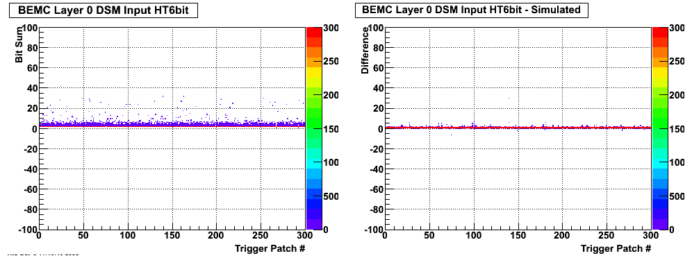
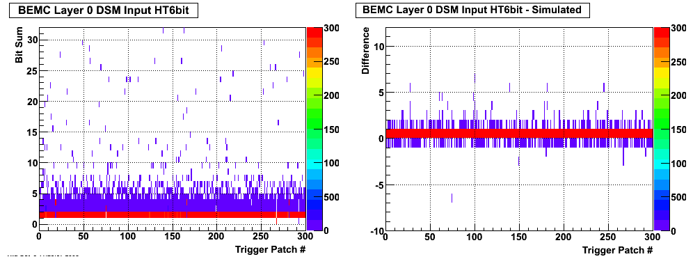
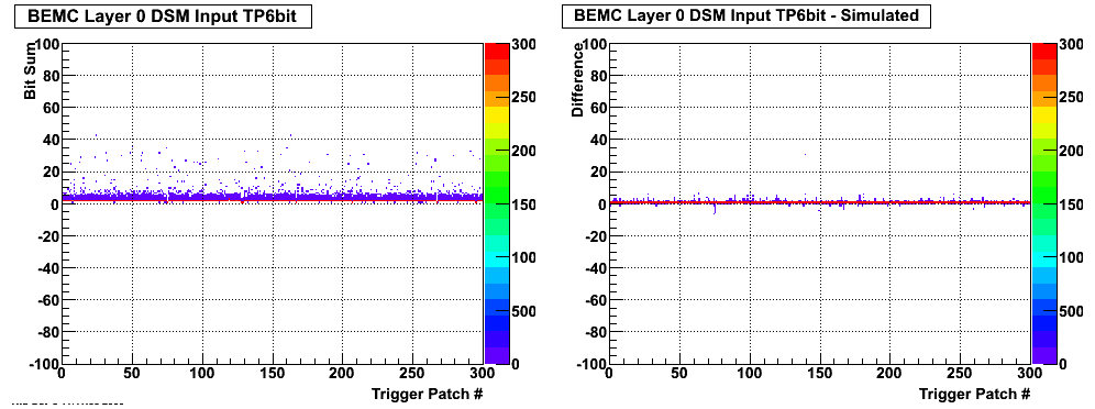
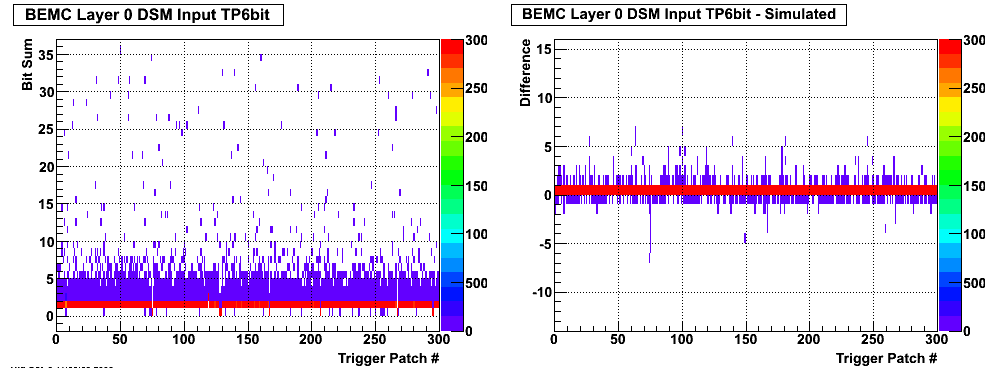
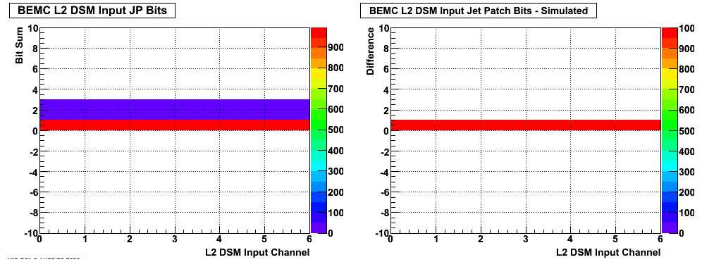
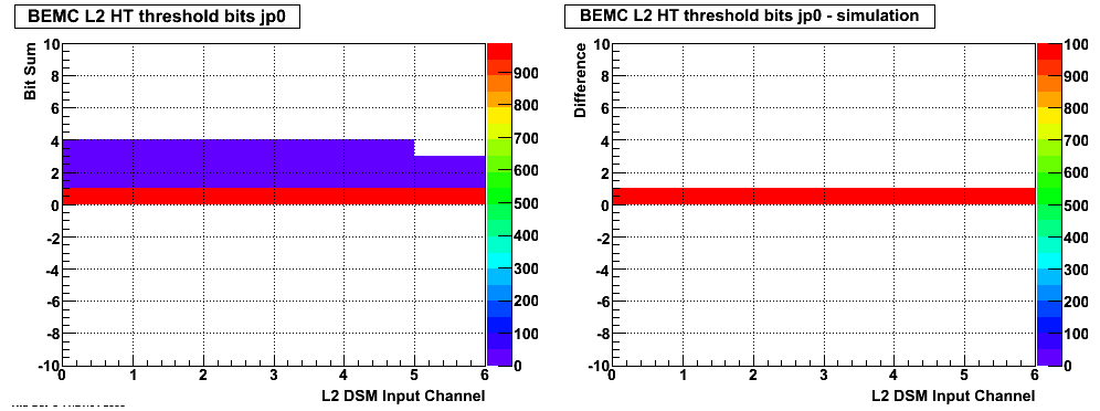
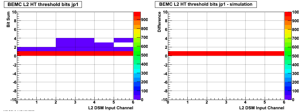
Left Plots show DSM input from data (L0) or simulation (L1, L2)
Right Plots show DSM input minus recreation from simulated reconstruction; these differences are optimally zero
Layer 0 BEMC Bits:
HT bits (0-5):
Zoom-in on horizontal axis of above plot:
TP Bits (6-11):
Zoom-in on horizontal axis of above plot:
Layer 1 BEMC Bits:
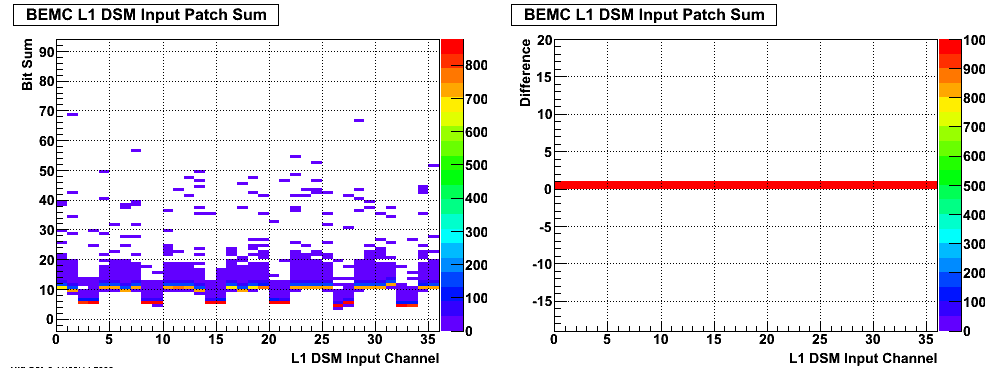
ADC-sum TP bits (0-9):
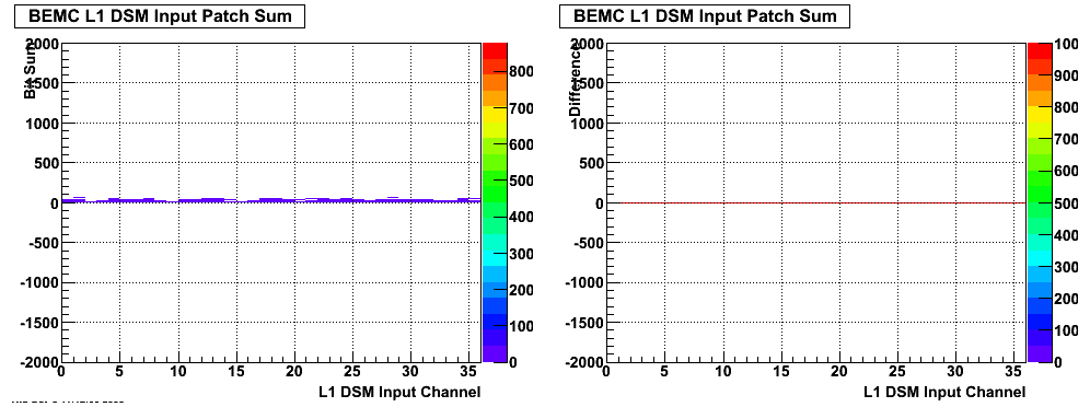
Zoom-in on horizontal axis of above plot:
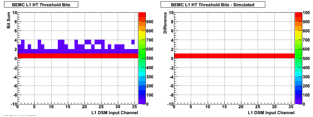
HT threshold bits (10-11):
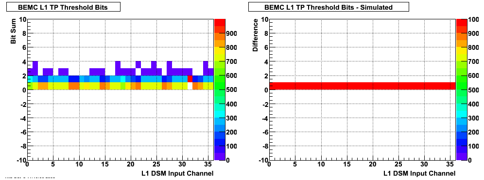
TP threshold bits (12-13):
HT AND TP threshold bits (14-15):
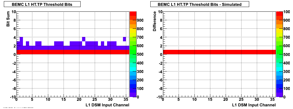
Layer 2 BEMC Bits:
Middle 5 bits of ADC energy sum (0-4):
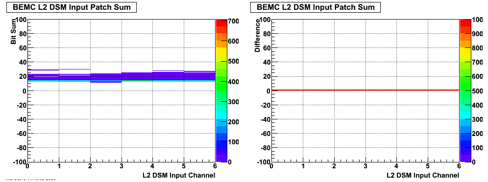
Zoom-in on horizontal axis of above plot:
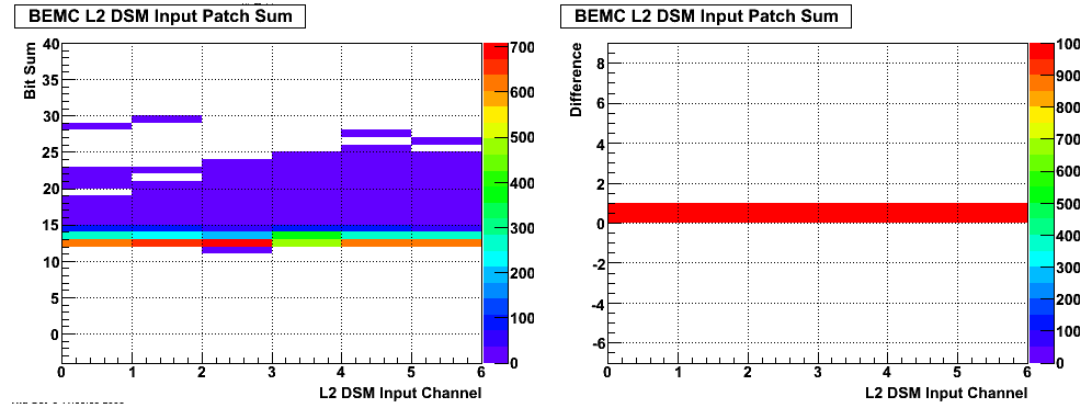
HT AND TP threshold bit, jp0 and jp1 combined (7):
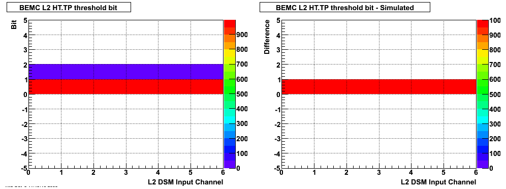
TP threshold bit, jp0 and jp1 combined (9):
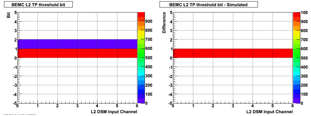
JP threshold bits, jp0 and jp1 combined (10-11):
HT threshold jp0 bits (12-13):
HT threshold jp1 bits (14-15):
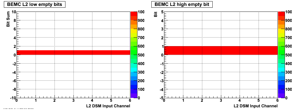
Empty bits (5,6; 8):
Documentation on bit definitions and Level 0,1,2 data processing can be found in the attached .pdf file:
http://drupal.star.bnl.gov/STAR/system/files/EMC_2006_pp.pdf
- fersch's blog
- Login or register to post comments
