Assembly of the roman pots - manual
0) – Prepare your tools: clean workspace with alcohol, ensure you have enough space, prepare 3/32’ allan (hex) screwdriver, [size] allan wrench and two supports. You may also need a little hammer and kapton tape. RP planes have two very fragile elements – silicon surface, and SVX chips. SVX chips are wire-boned to the silicon. Just a delicate, slight touch WILL break them.
1) Put the metal case on the grip and the support.
2) Put RP planes in the case, SVX side down. From this side point of veiw, the planes should go: A on the bottom, then B, C and D on the top. Connect each subsequent plane to the case with little side screws, before you put the next one. Note, that middle alignment pin should go through every plane – you shouldn’t remove that pin as it is permanently attached to the metal case. Also side screws shouldn’t be screwed in too tightly for now.
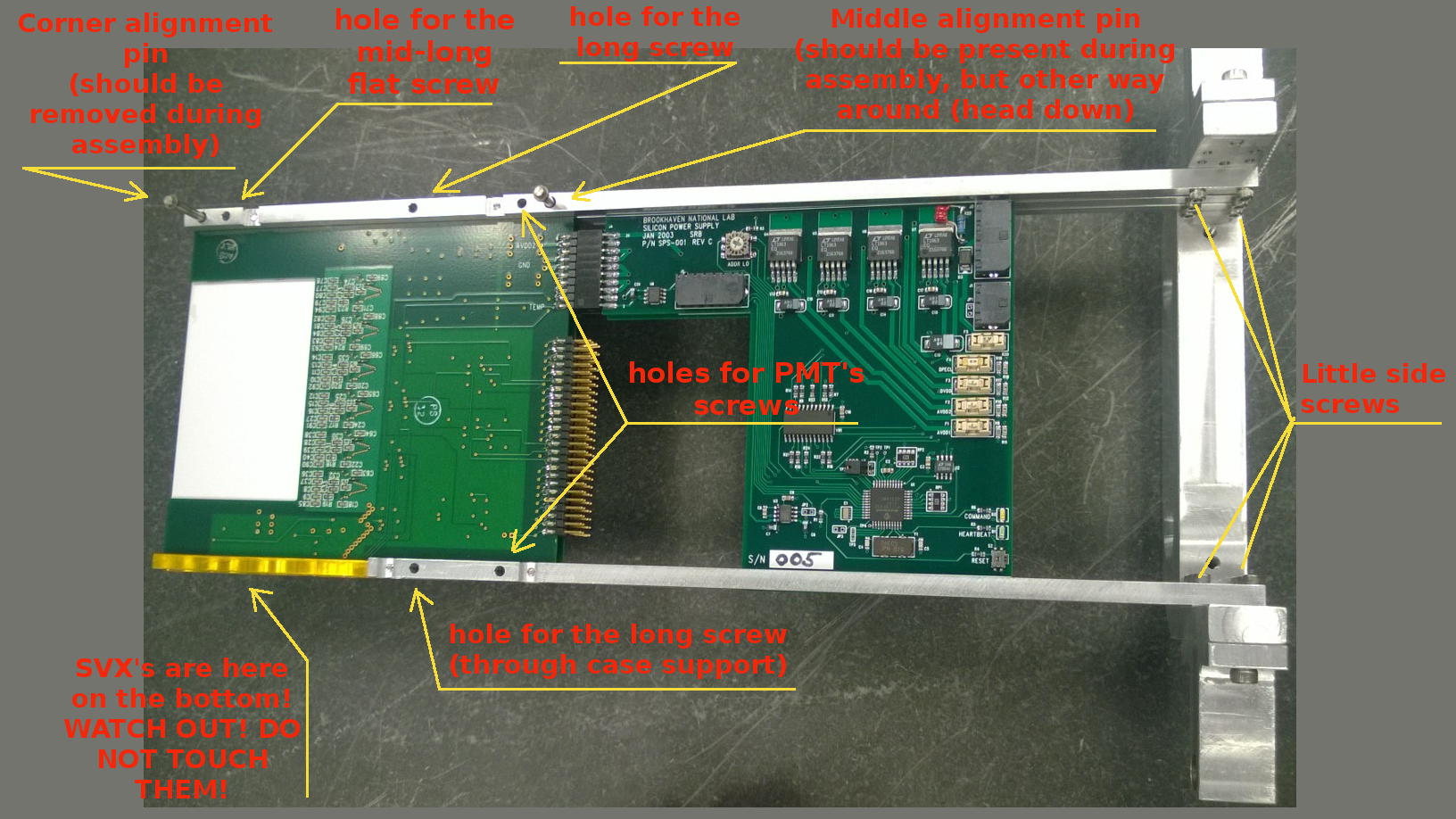
Illustration 1: Beginning of the assmembly: on the picture two planes are present: A (on the bottom) and B (on the top). Corner alignment pin should be taken out for the assembly. Note, that middle alignment pin is placed in the wrong way.
3) Turn everything on the other side, use the supports. Now you should have SVX chips facing up.
4) Put in:
- Alignment pin in the corner (it is a bit tight, put it in using screwing motion. You can use a little hammer, but be very gentle)
- Mid-long screw with a flat head, near the alignment pin.
- Long screws: through the case on the same side and through the case support on the other
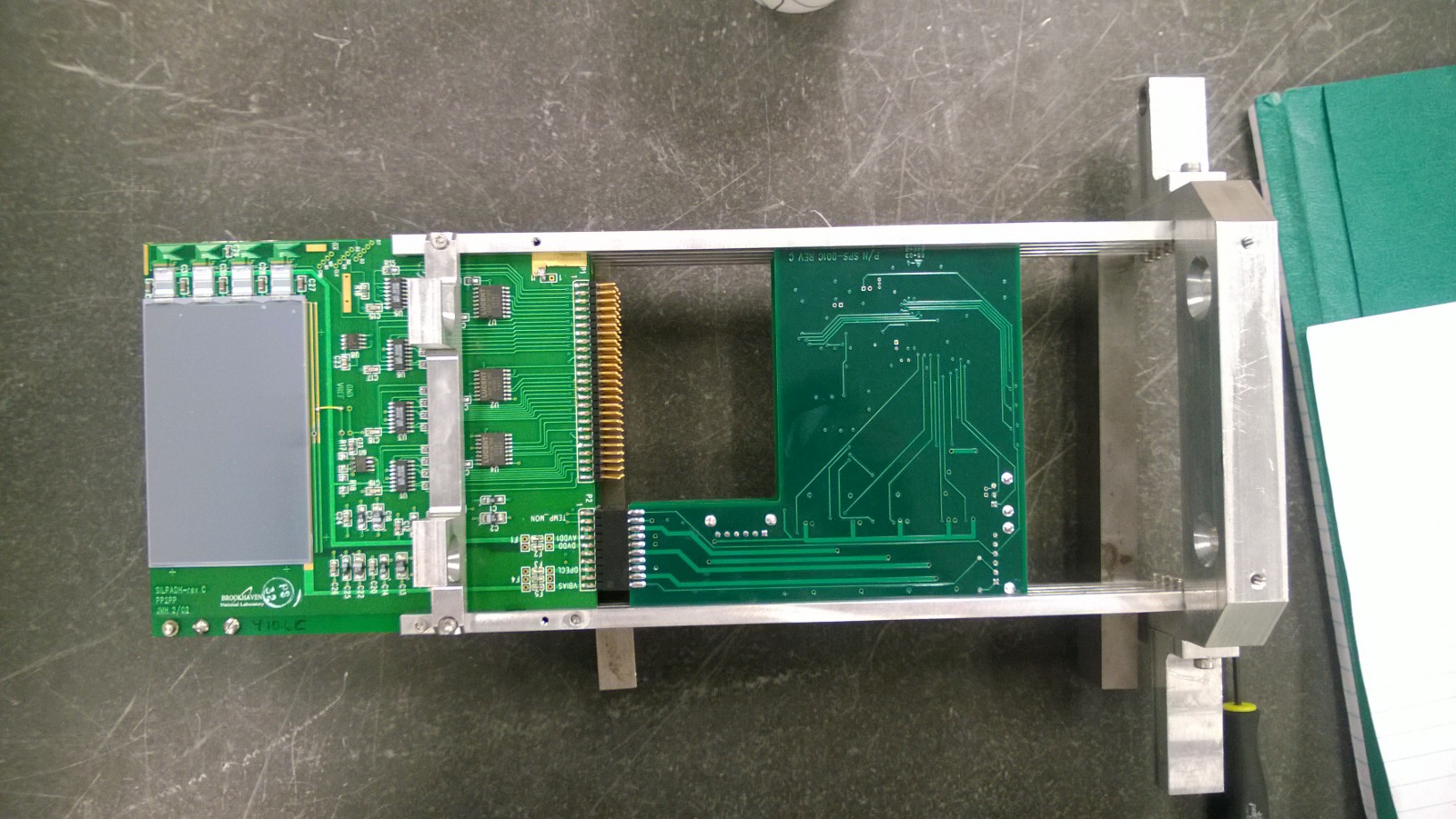
Illustration 2: Other side of the RP. Note that RP is placed on the support (two metal blocks in this case). All screws are in (middle pin is istill in the wrong way though..)
5) Tighten screws, including the little side ones. Turn everything on the other side (remove support). Now SVX’s should face down.
6) Put collar on the corner alignment pin, screw it in using little allan wrench. You should be left with two holes through RP, and the only thing that should excess level of the case is the collar of alignment pin (i.e. no screw heads should be on this side).
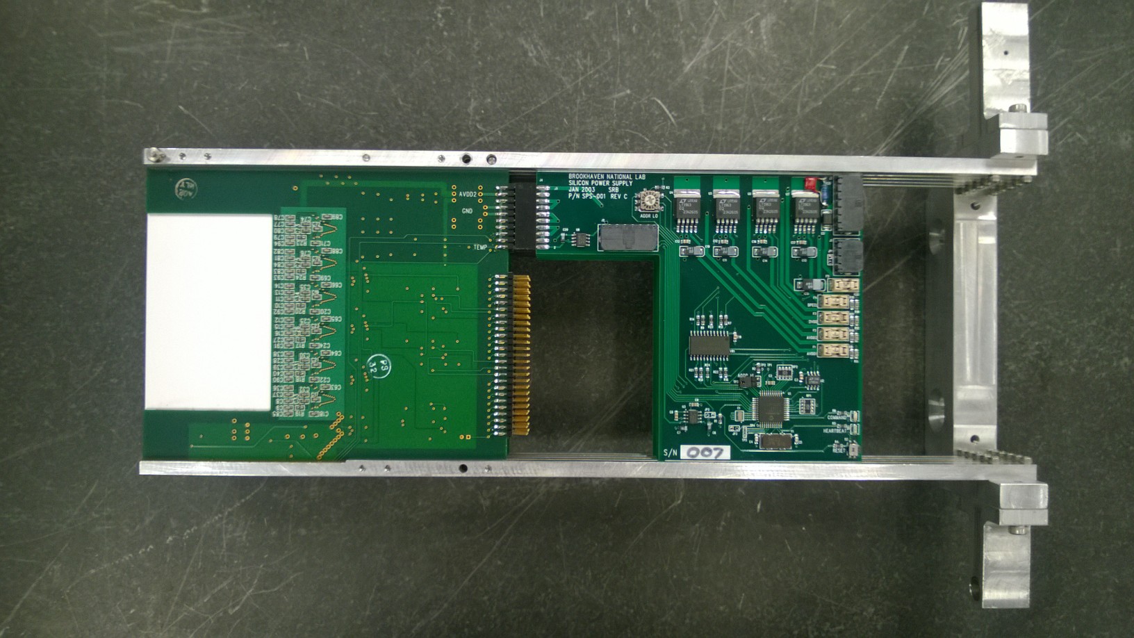
Illustration 3: That how it should look! Note that middle alignment pin does not go completely through the case (it ends in ~half ot the top plane width)
7) Put PMT’s – align holes of the PMT support with holes in RP case.
8) Connect PMT’s to the RP with two long, flat-headed screws. Dont’t screw them in yet.

Illustration 4: Do not tight PMT screws yet - you will have to align scintillator with the silicon layer
9) Put zip-lock around RP just below photo tubes. You might have to use two zip-locks connected with each other. Note that “lock” part is facing up and is not exceeding RP contour. Zip it tight enough so it won’t move, but not too tight, so it won’t generate excessive pressure on this side of RP. Goal of this created band is not to hold the RP planes, but to create support for PMT’s. Cut off excess of the zip-locks.
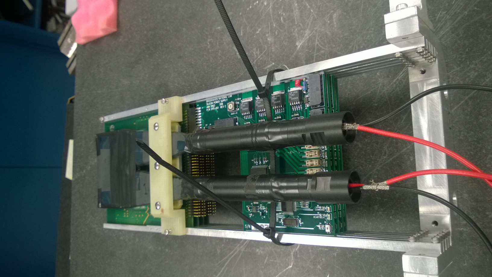
Illustration 5: This zip-lock band will create support for the PMT's. Notice the position of the 'locks'!
10) Align PMT’s with the silicon layer – use e.g. metal block with flat surface. Watch out for SVX which are on the bottom. When PMT’s are aligned, screw them tightly.
11) Use small zip-locks to attach PMT’s to the band you created in 9). Watch out for the light isolation on PMT, which might be broken with sharp tools.
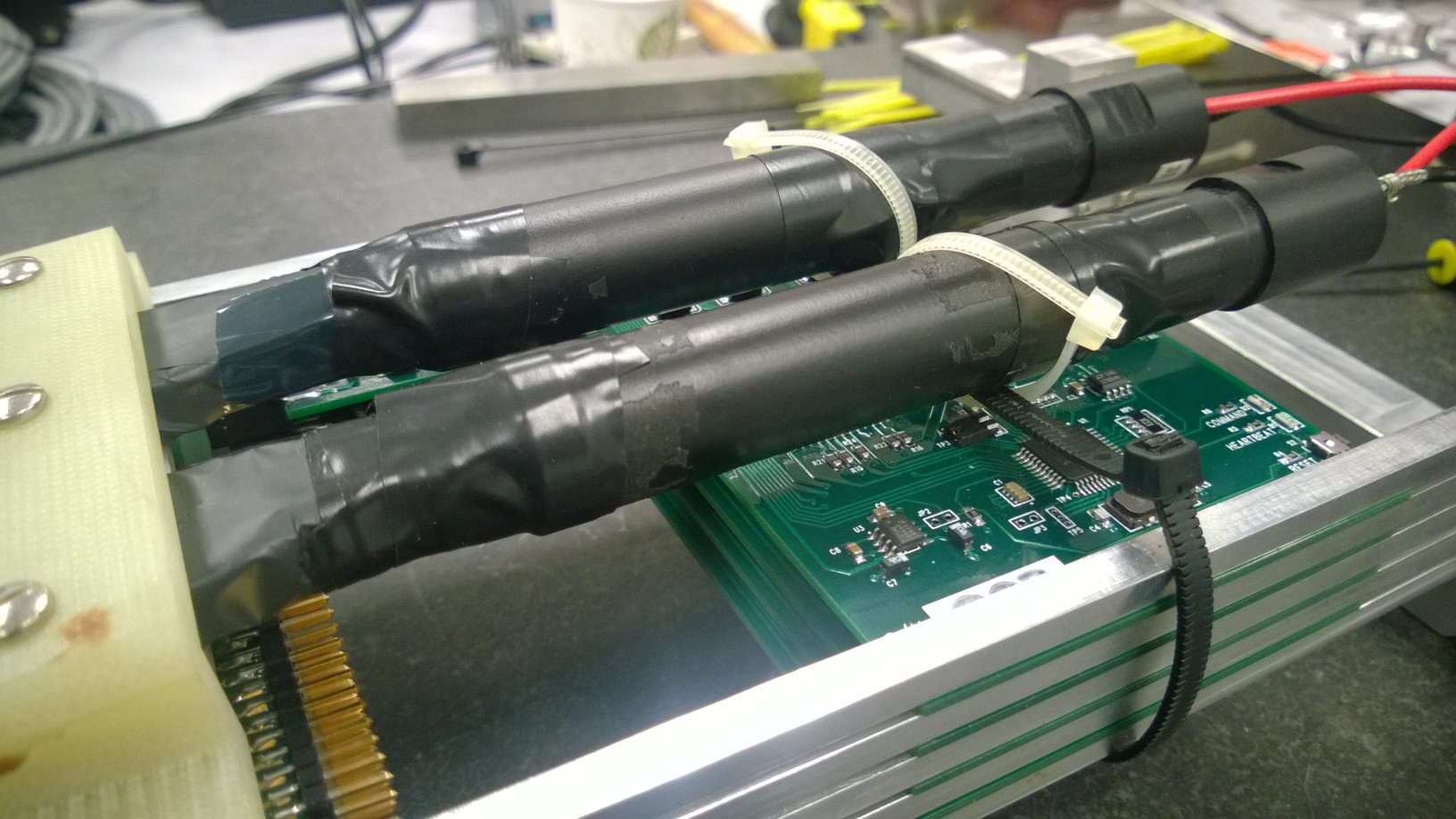
Illustration 6: There we go! This looks steady, isn’t it!
12) Put the kapton tape on the case. WATCH OUT FOR THE SVX’S ON THE BOTTOM!
13) That’s it! Put RP gently in the box and secure it. Remember to label the box.
- andlip's blog
- Login or register to post comments