- dilks's home page
- Posts
- 2019
- 2018
- December (1)
- November (1)
- October (1)
- August (2)
- July (4)
- June (3)
- May (1)
- April (2)
- March (2)
- February (1)
- January (5)
- 2017
- December (3)
- November (1)
- October (2)
- September (3)
- August (2)
- July (2)
- June (1)
- May (2)
- March (3)
- February (3)
- January (3)
- 2016
- November (2)
- September (4)
- August (2)
- July (6)
- June (2)
- May (3)
- April (1)
- March (2)
- February (3)
- January (2)
- 2015
- December (3)
- October (3)
- September (2)
- August (6)
- June (3)
- May (3)
- April (4)
- March (3)
- February (5)
- January (3)
- 2014
- December (1)
- November (1)
- October (3)
- September (4)
- August (3)
- July (3)
- June (2)
- May (2)
- April (2)
- March (1)
- 2013
- 2012
- 2011
- My blog
- Post new blog entry
- All blogs
uvLED Array Construction Photos
Updated on Thu, 2017-02-09 19:58. Originally created by dilks on 2017-02-09 19:21.
Here are some photos taken from the initial design of the uvLED array to after its installation and use in the FMS.
Right click and open any image in a new tab to view the full resolution.
.
.
.
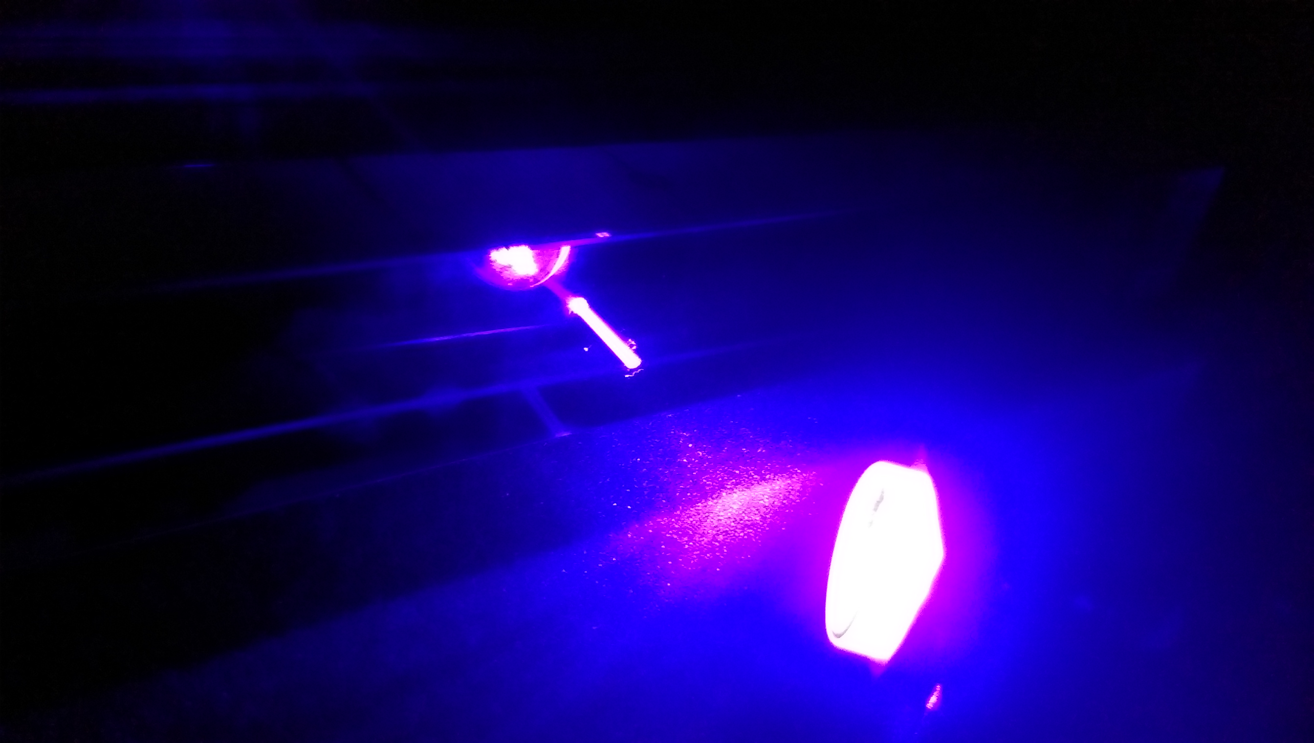
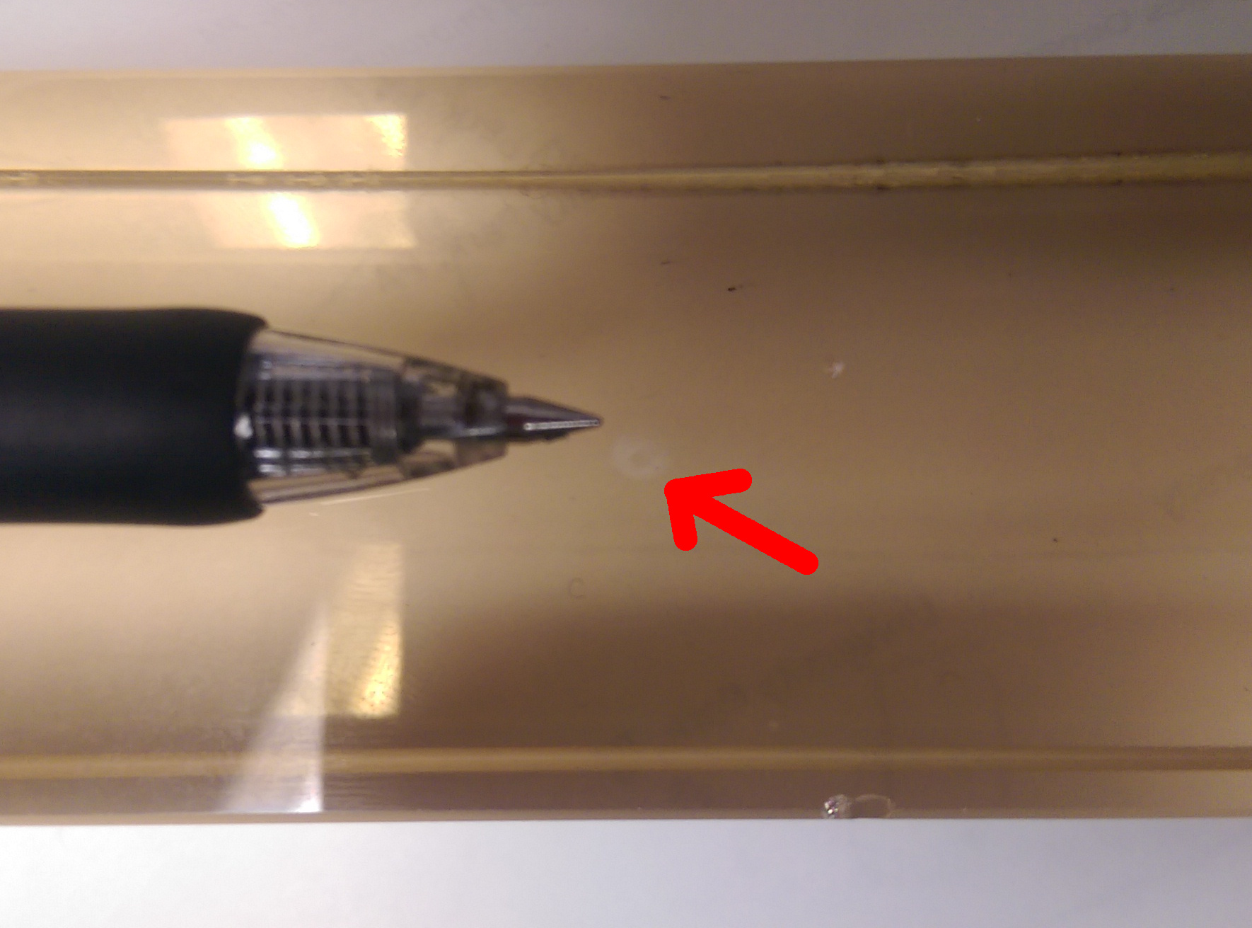
Testing 405 nm laser in a radiation-damaged cell, to see if we can 'drill a hole' through the damage
.
.
Hole drilled! It looks like a cylinder because the beam was rather non-uniform
.
.
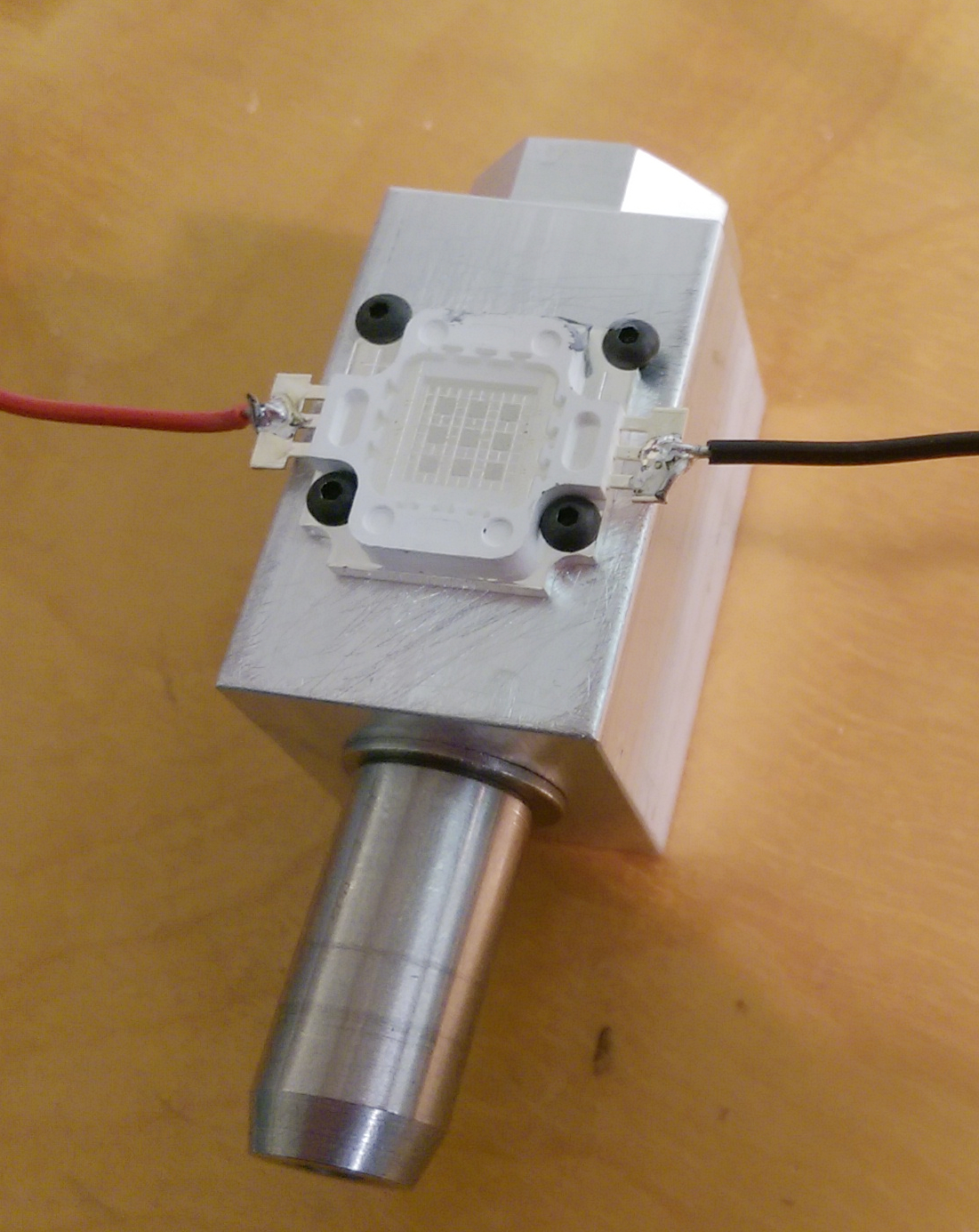
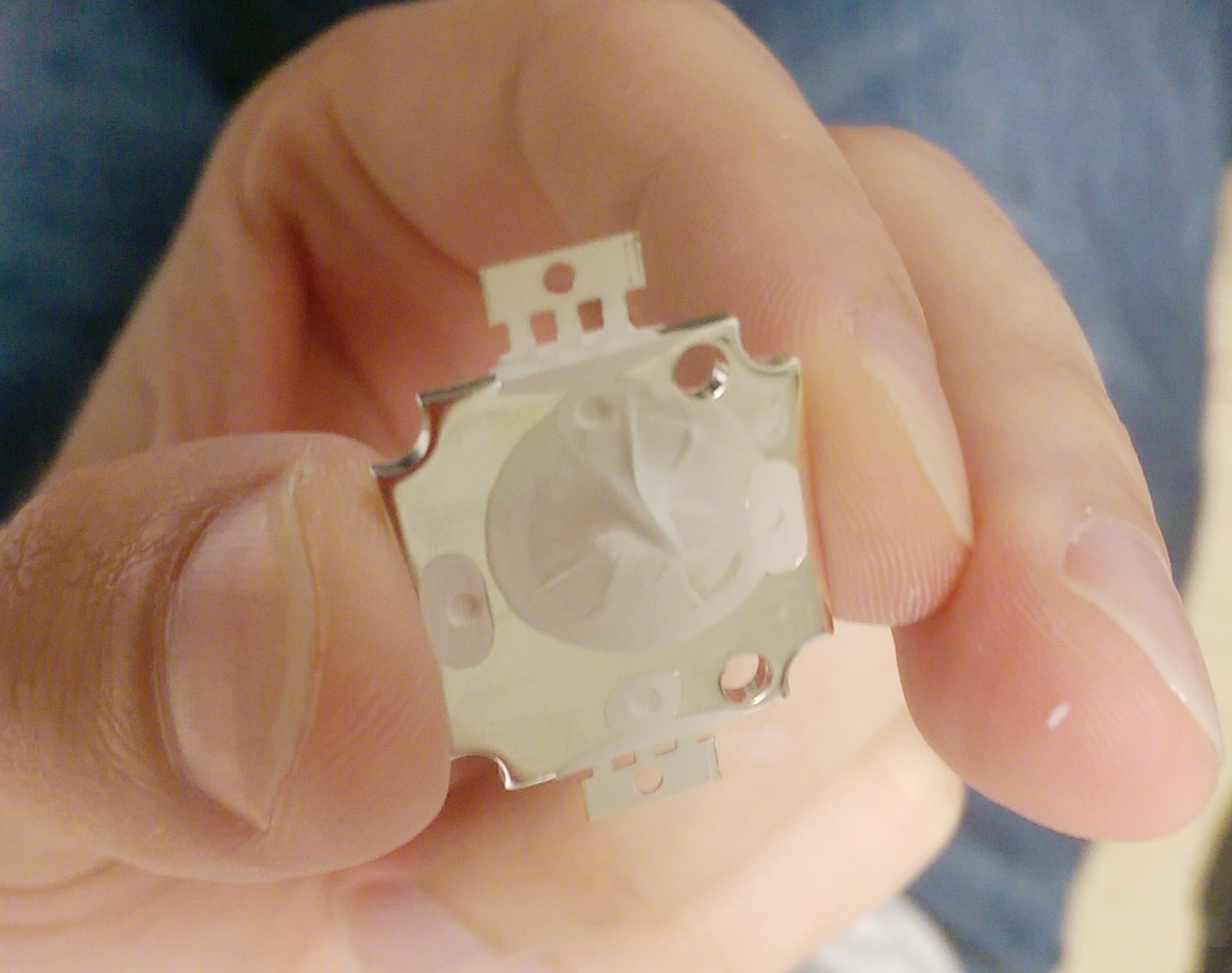
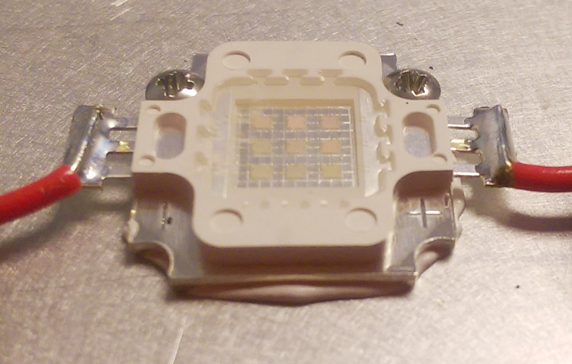
Our first uvLED used for curing rate testing. Mounted to an aluminum heatsink, since the first one wasn't and went up in smoke after bringing it to full power
.
.
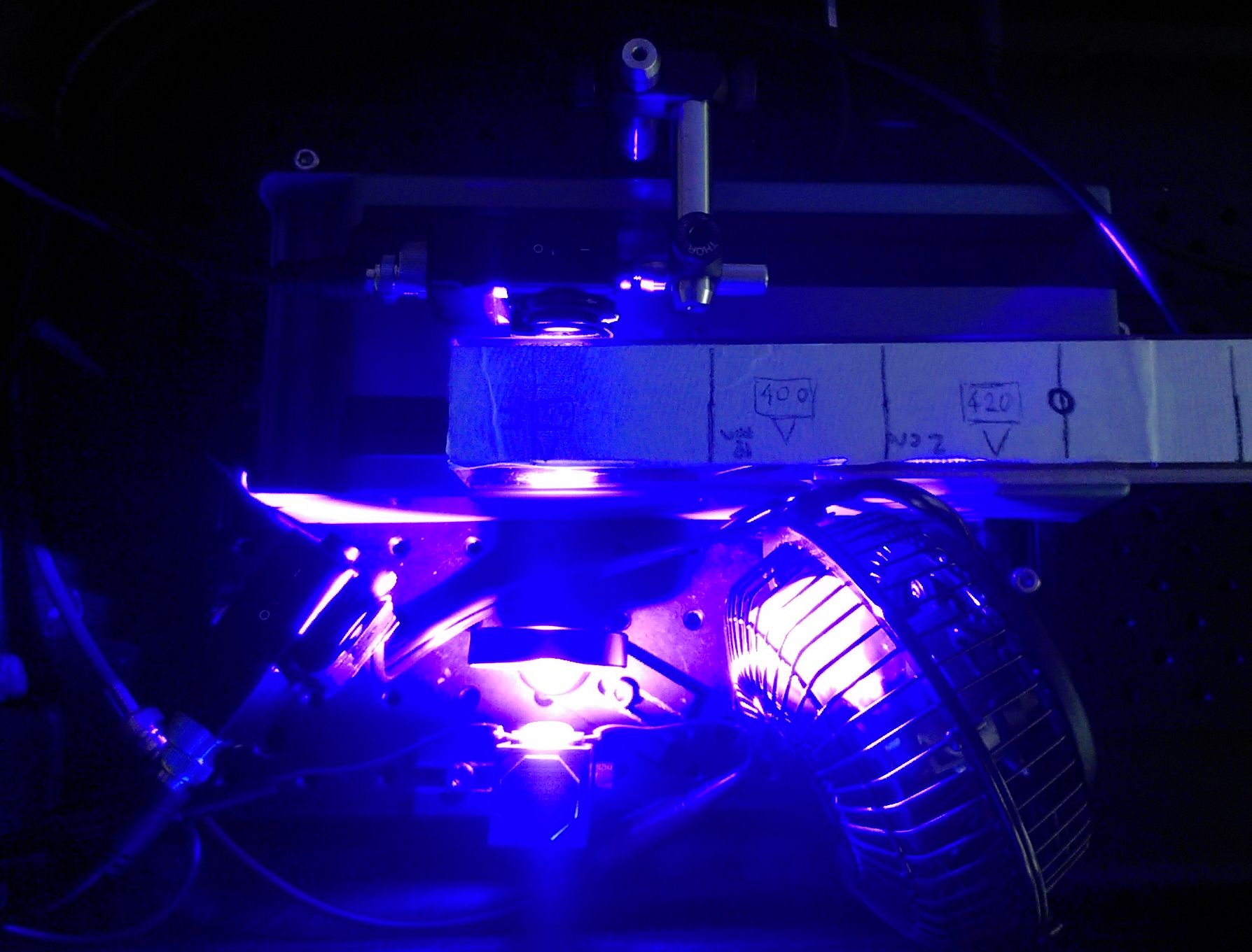
uvLED curing rate test setup, with two photodiodes for data aquisition as well as a fan for additional cooling
.
.
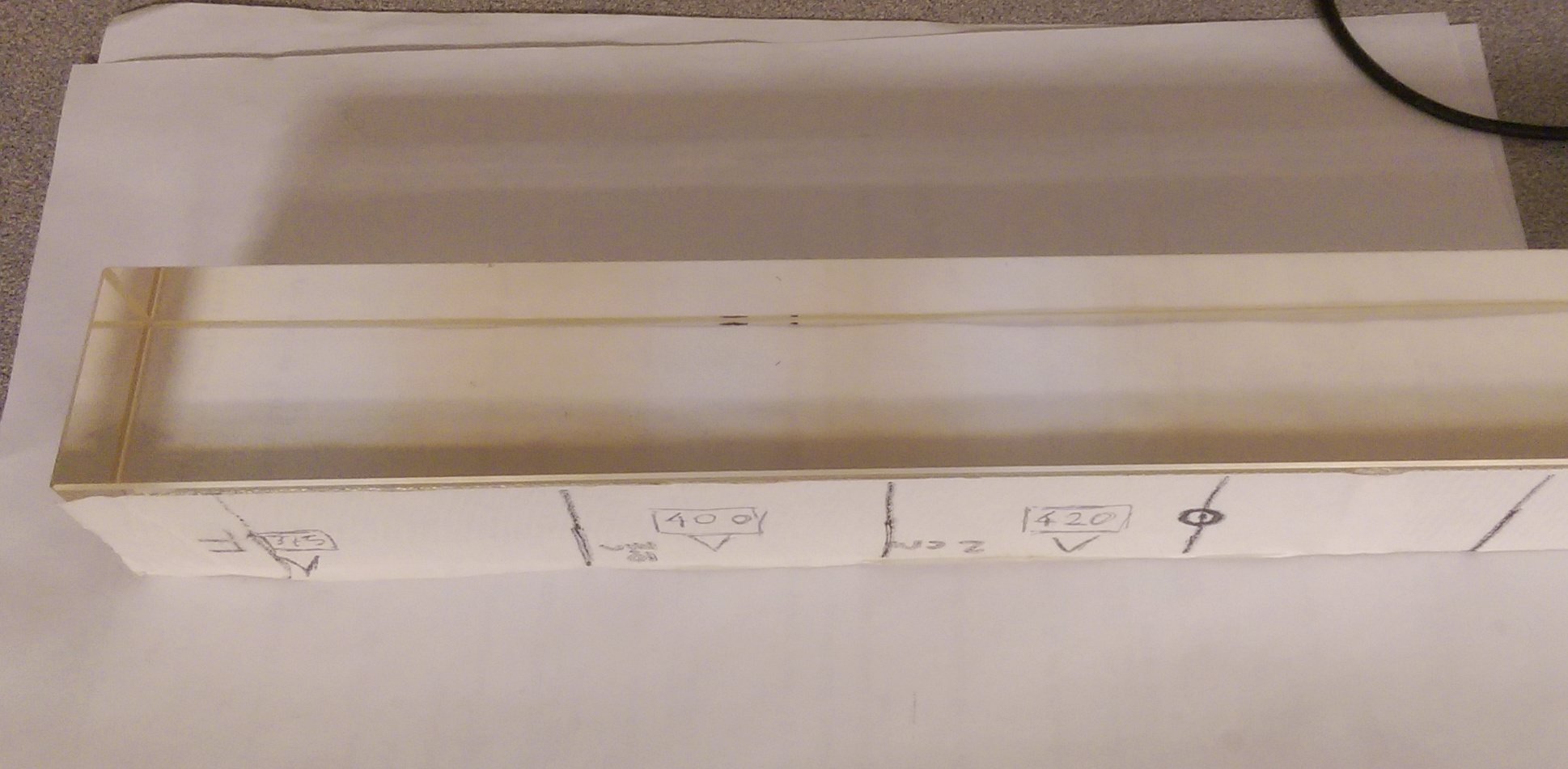
Some test results (uvLED frequencies written on tape)
.
.
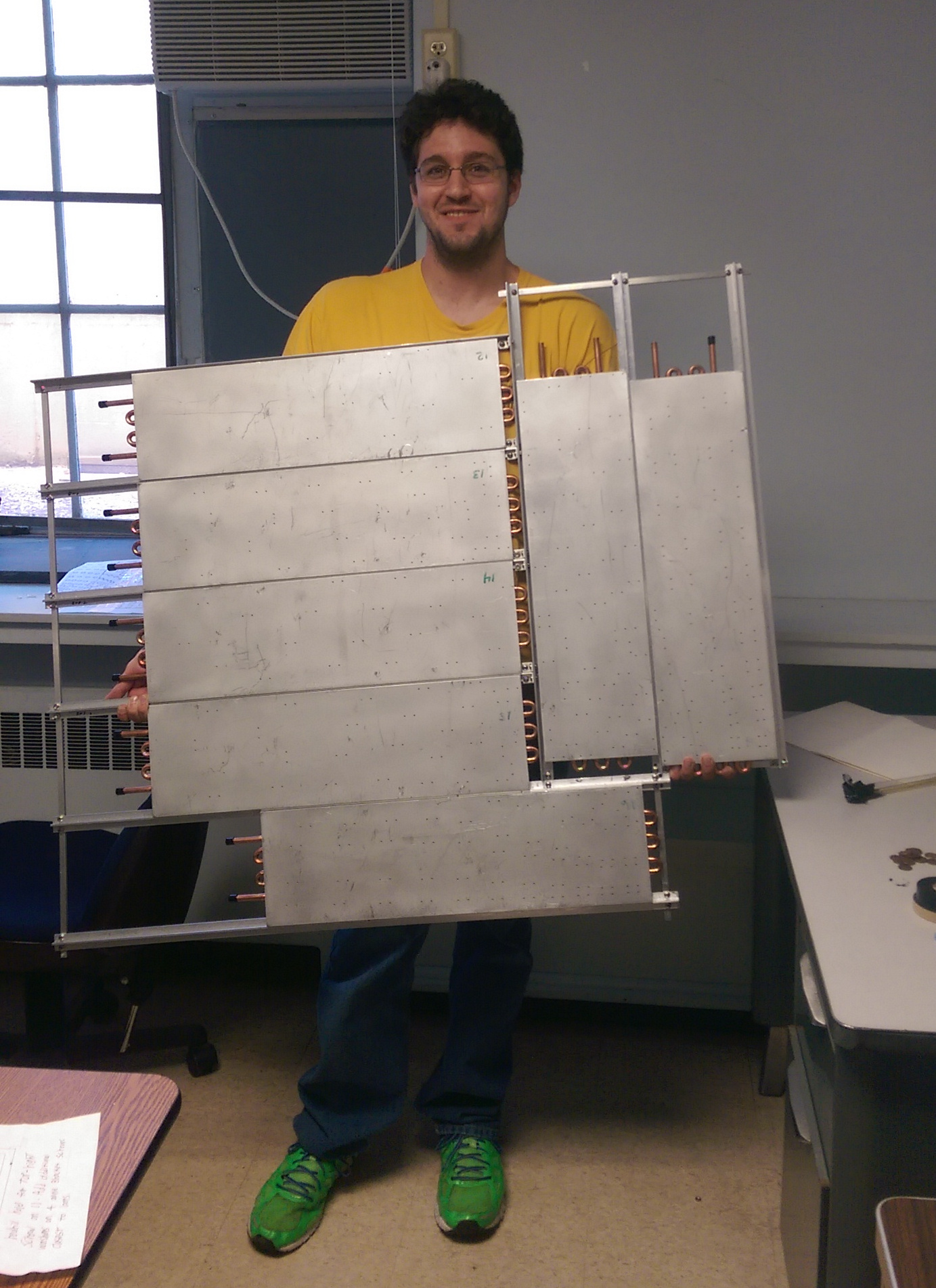
Branden and the frame for 1 quadrant of cold plates; holes are drilled and ready for uvLEDs to be mounted
.
.
First apply thermal paste...
.
.
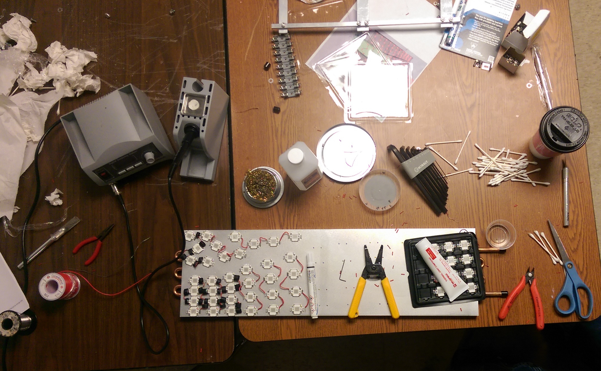
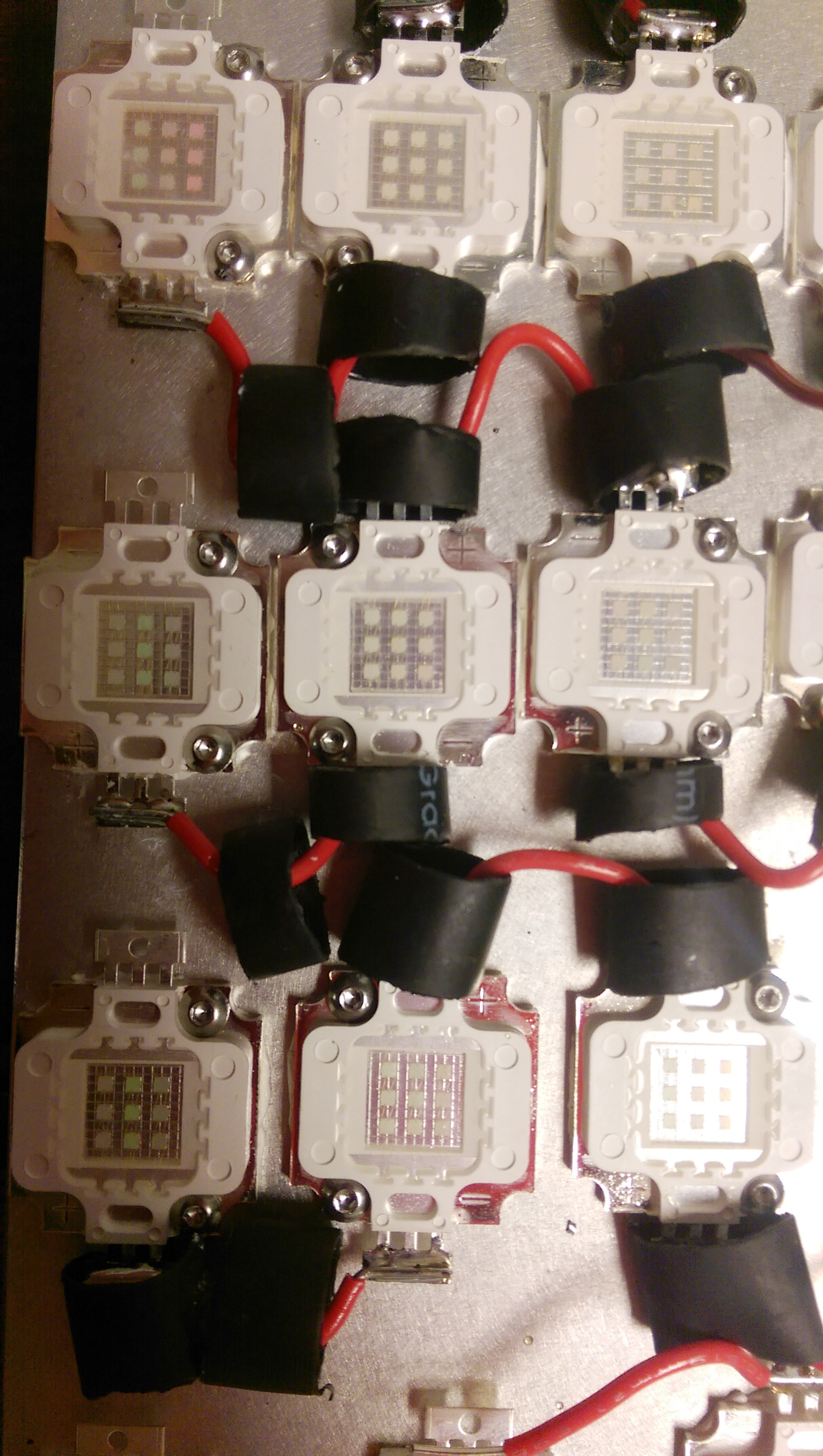
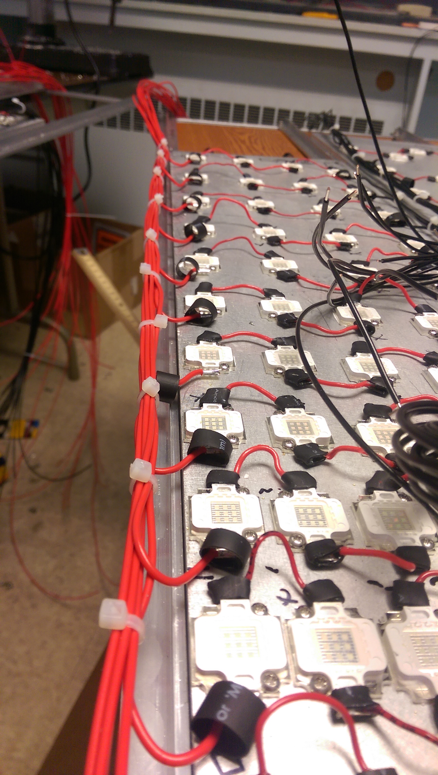
...then screw it on and solder some wires
.
.
work zone
.
.
Add heatshrink and rinse and repeat, ~1,000 times
.
.
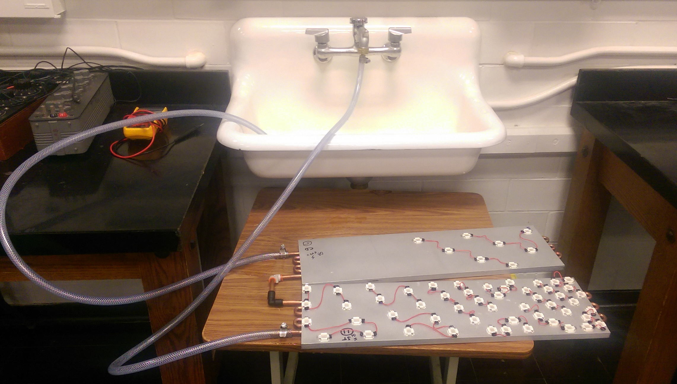
Some initial water flow testing
.
.
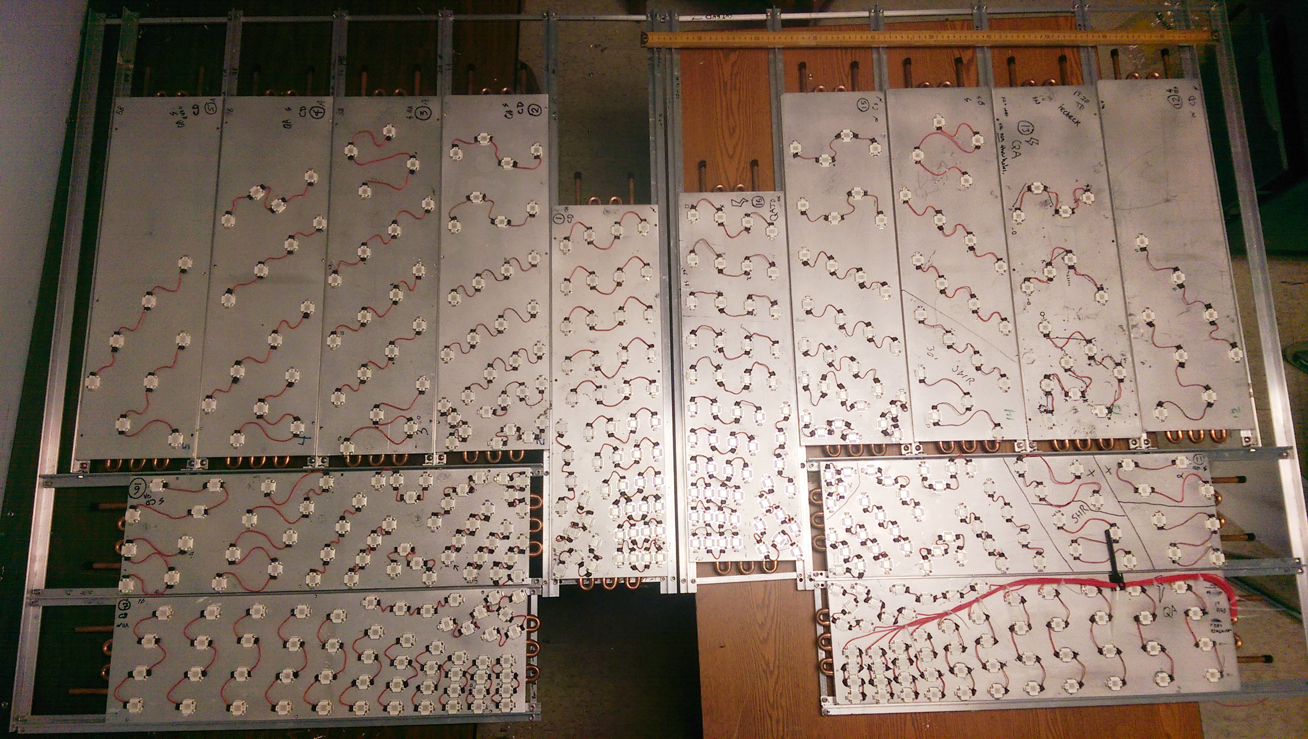
Halfway done!
.
.
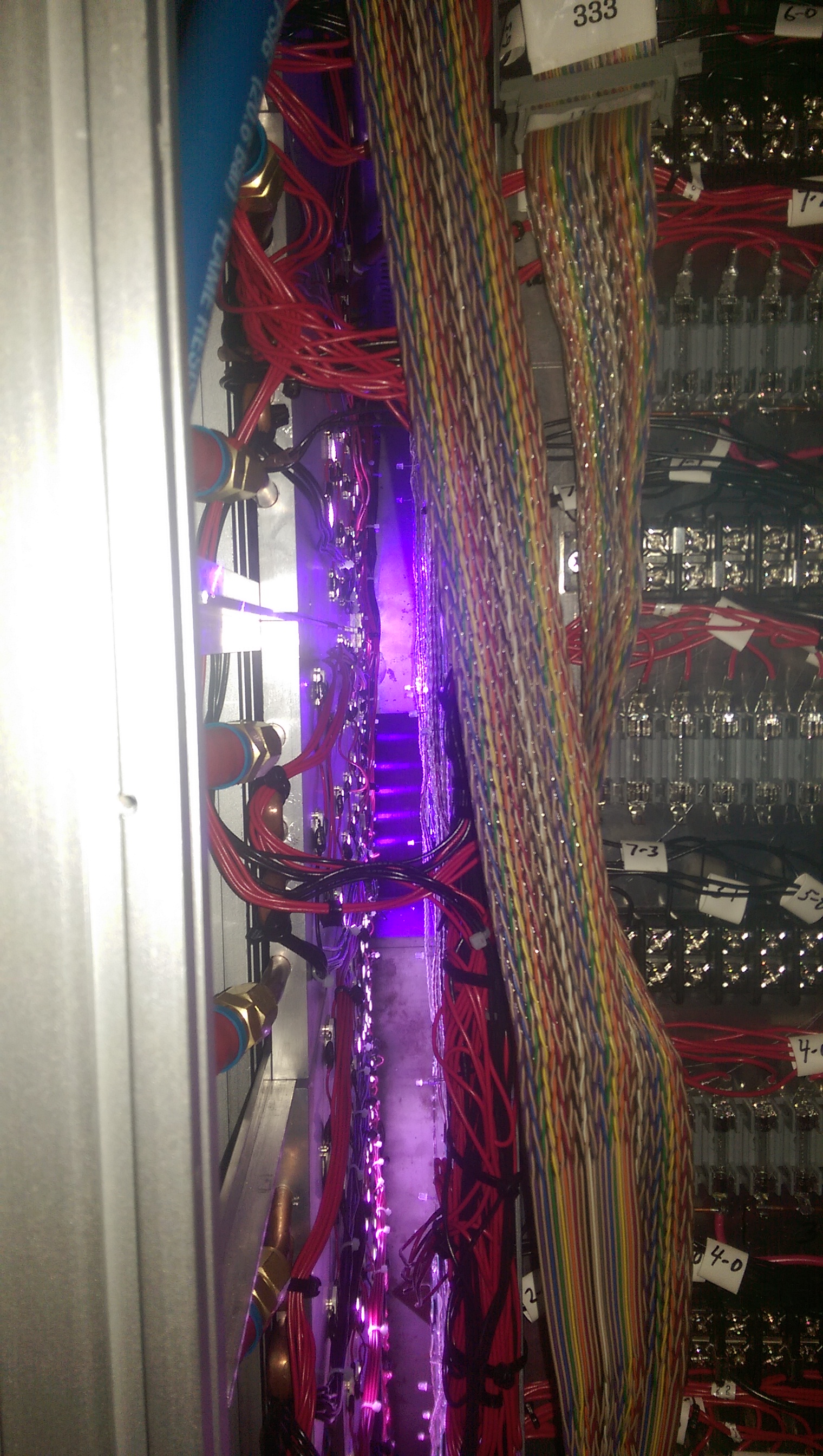
Connecting external wires
.
.
At times things got messy

.
.
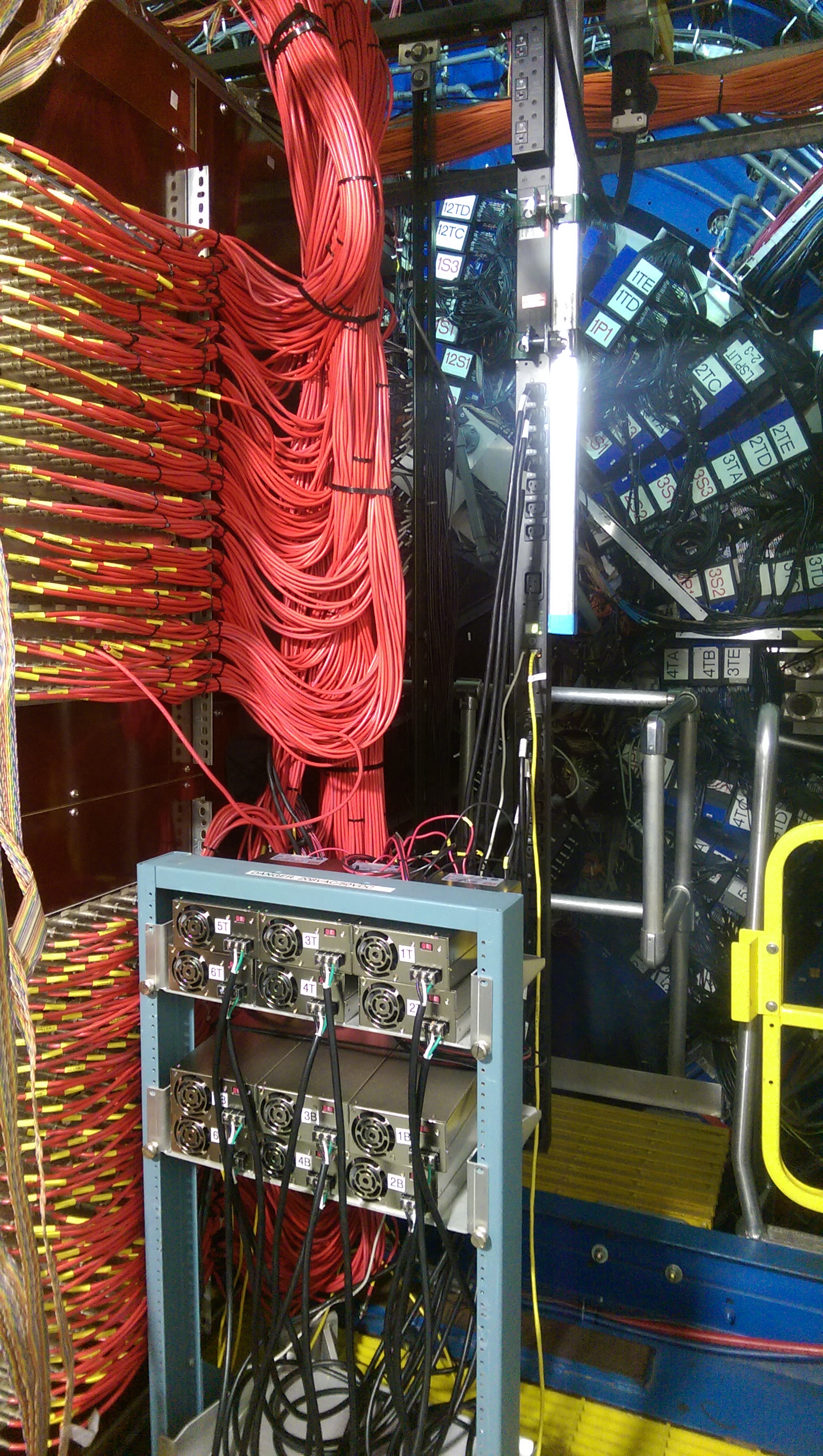
Fuse blocks and ground plates ready for installation

.
.
Installation, plumbing, and wiring done!
.
.
Power Supplies installed and wired
.
.
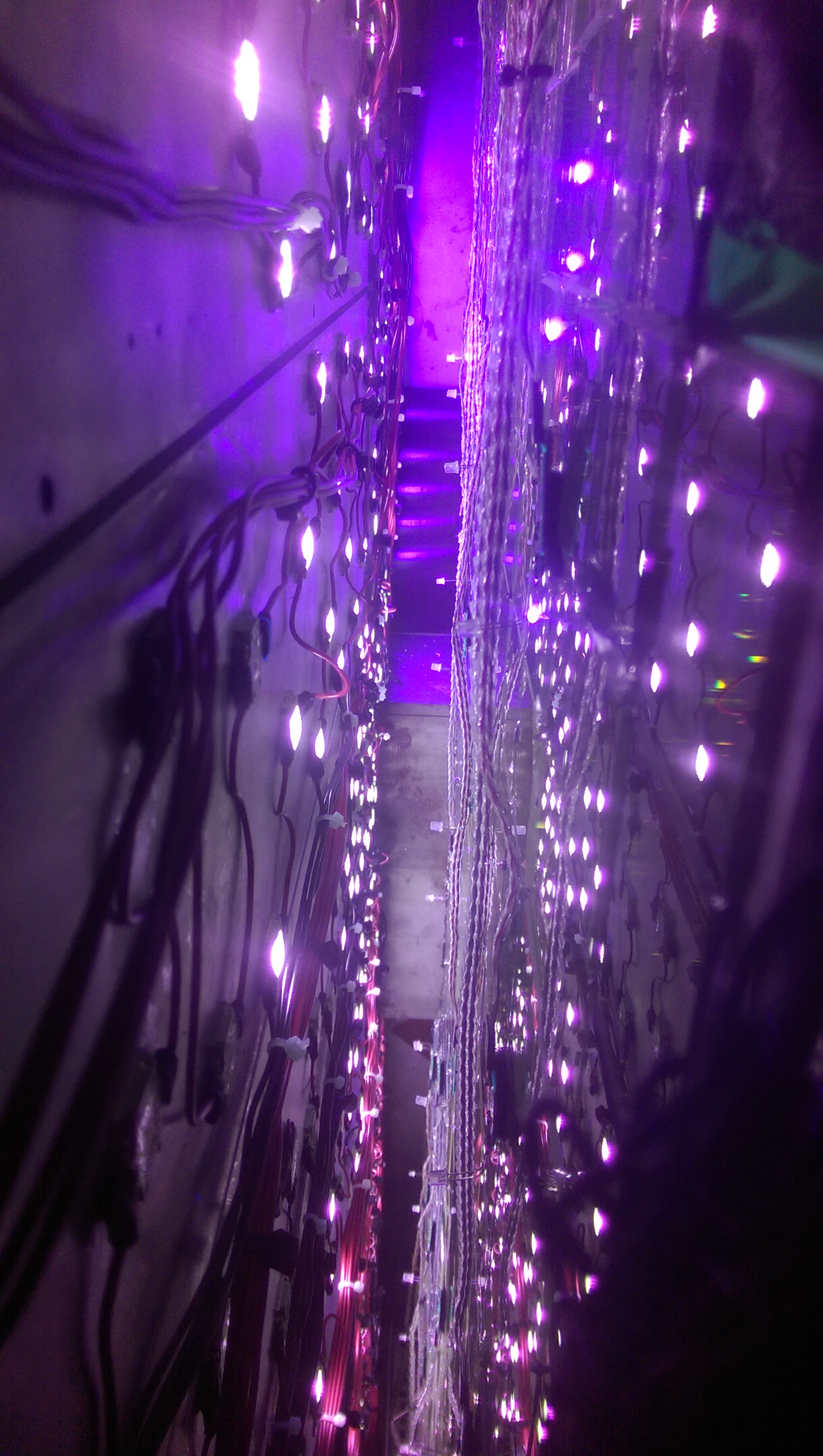
FMS curing in action
»
- dilks's blog
- Login or register to post comments