Distortion maps for TPC GG Voltage Error
These maps show the distortions in r-phi and r for TPC hits due to a 1 mm shift in the west TPC Gated Grid position, corresponding to a 13.5V error (the main E field is 135 V/cm). All units are [cm]:
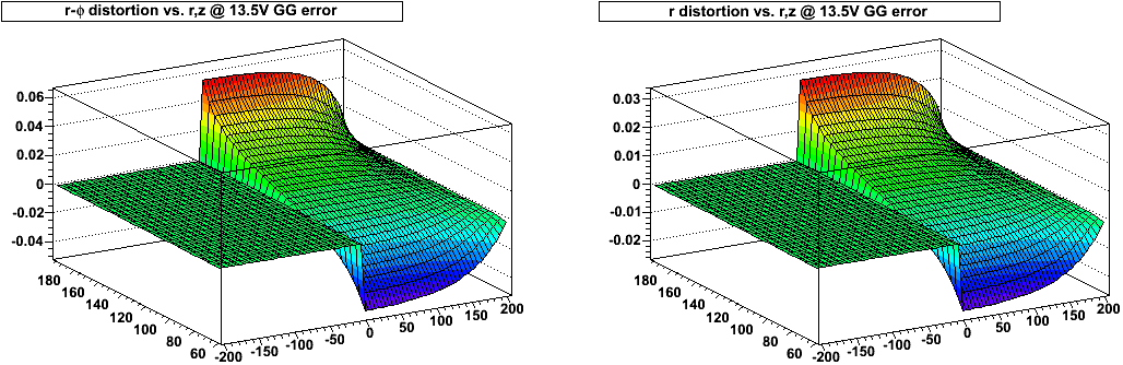
The sign of these distortions flip with the sign of the B field.
This is relevant for the TPC alignment calibration results reported by Yuri using intra-sector fits of 6 parameters (rotations+translations along 3 axes), which show that there can be translations of order 1 mm in z between inner and outer sectors. Also shown are rotations alpha (about the x axis) and beta (about the y axis) which can lead to additional displacements of the Gated Grid in z. For example, a 0.5 mrad rotation about the y axis can lead to a 300 micron (0.03 cm) difference in z displacement over a 60 cm span (the distance between padrows 1 and 13, for example), which translates to a voltage error difference of ~4 V.
These z displacements lead to a small z position reconstruction error, as Yuri finds, and also to an E field distortion which will introduce azimuthal and radial position reconstruction errors which are, juddging by the above plots, smaller, but perhaps within an order of magnitude as the z error. However, to do it correctly, the displacements must be treated sector-by-sector, and using a 3D distortion correction code as these distortions will not be phi symmetric. This is not yet in place, but it appears to be relevant. As the z displacement will then vary over the face of the Gated Grid on the endcap, the resulting distortions could be smaller than the above-plotted effect of shifting the entire endcap.
CONCLUSION: distortions caused by z displacements in alignment need to be considered in the E field distortions and treated when doing the iterative alignment procedure.
-Gene
- genevb's blog
- Login or register to post comments