- genevb's home page
- Posts
- 2025
- 2024
- 2023
- 2022
- September (1)
- 2021
- 2020
- 2019
- 2018
- 2017
- December (1)
- October (3)
- September (1)
- August (1)
- July (2)
- June (2)
- April (2)
- March (2)
- February (1)
- 2016
- November (2)
- September (1)
- August (2)
- July (1)
- June (2)
- May (2)
- April (1)
- March (5)
- February (2)
- January (1)
- 2015
- December (1)
- October (1)
- September (2)
- June (1)
- May (2)
- April (2)
- March (3)
- February (1)
- January (3)
- 2014
- 2013
- 2012
- 2011
- January (3)
- 2010
- February (4)
- 2009
- 2008
- 2005
- October (1)
- My blog
- Post new blog entry
- All blogs
Distortion maps for Triple 3D GridLeak
Updated on Thu, 2016-08-11 13:51. Originally created by genevb on 2016-08-09 16:13.
(A limited You do not have access to view this node of this topic was given at the 2016-08-10 S&C meeting)
Notes:
Inner HV @ 1100 V, Outer HV @ 1390 V (typical of recent operations)
Inner HV @ 1170 V, Outer HV @ 1390 V (nominal operating voltages)
Inner HV @ 1100 V, Outer HV @ 1390 V (typical of recent operations)
-Gene
Notes:
- Input for charge sheet widths and relative total charge in sheets taken from Irakli's results:
- Inner sector, inner leak width = 0.81 cm, charge = -42.15 + exp(0.005345*V)
- Inner sector, outer leak width = 0.85 cm, charge = -21.76 + exp(0.005123*V)
- outer sector, inner leak width = 0.99 cm, charge = -16.68 + exp(0.004731*V)
- outer sector, outer leak width = 1.04 cm, charge = -23.38 + exp(0.004751*V)
- Irakli's results for fitting a constant to the regions where voltage wasn't changed imply that there's an uncertainty at the level of ~2-3% on the calculated charges, which I have ignored hereafter.
- Historical middle GridLeak assumed a charge sheet of width 1.595 cm (the spacing between the last inner GG wire and the first outer GG wire), while Irakli finds a total inner + outer width of (0.85+0.99) = 1.84 cm. I will scale charge densities for new calculations by 1.595/1.84 = 0.8668 to preserve same total charge for middle GridLeak.
- Irakli's results were "per incoming electron", so I have scaled them by the radial form we use for SpaceCharge. This has the following impacts:
- The inner leak increases by 276%
- The outer leak decreases by 60%
- The middle leak now varies over its φ span, decreasing by almost 6% at the sector boundaries
- Test maps are created using a timestamp of "2016-04-30 05:17:00" during run 17121001, with SpaceChargeR2 = 0.0343452 C/ε0, EWRatio = 1.096, GL = 9.6, drift velocity 5.570 cm/μsec, BField -4.98975 kGauss.
- Some tests were done with varying the granularity of map on which charge was distributed for distortion calculations: negligible sensitivity was seen.
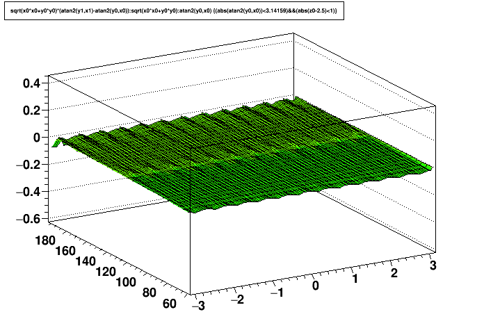
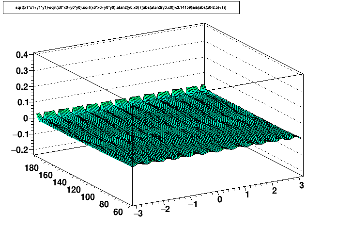
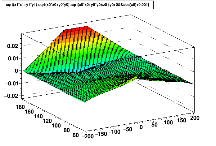
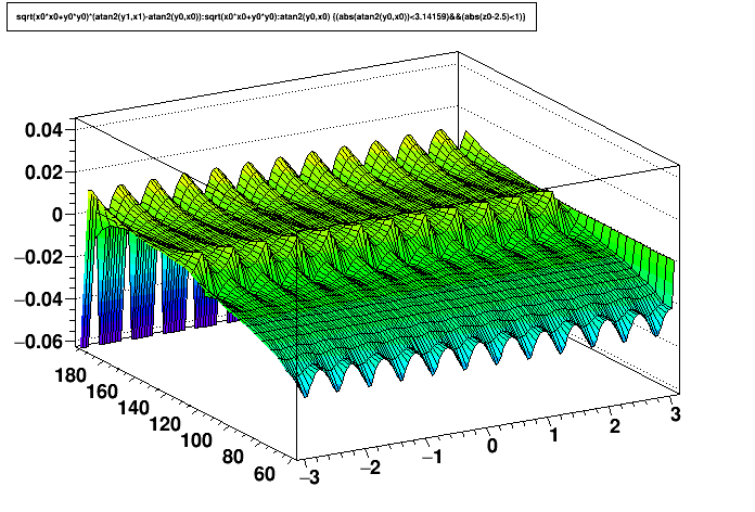
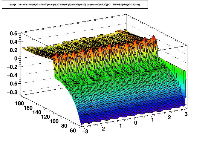
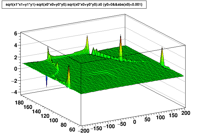
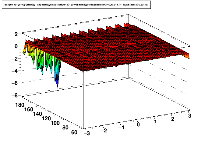
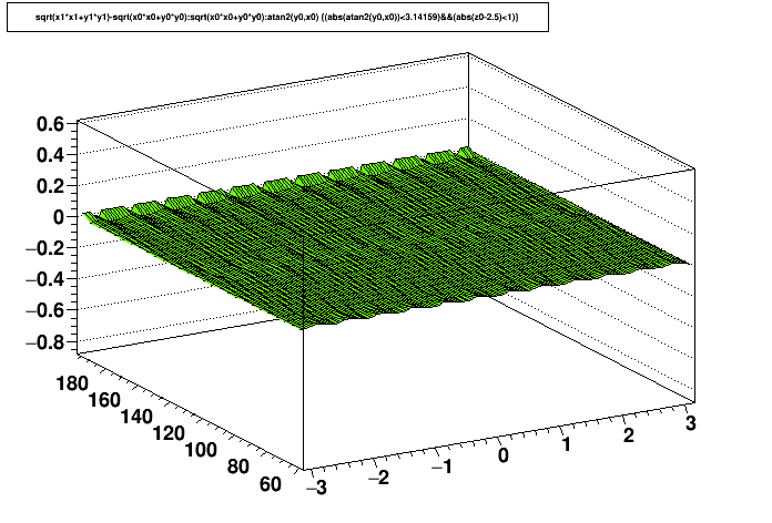
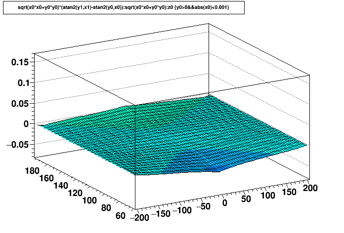
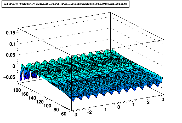
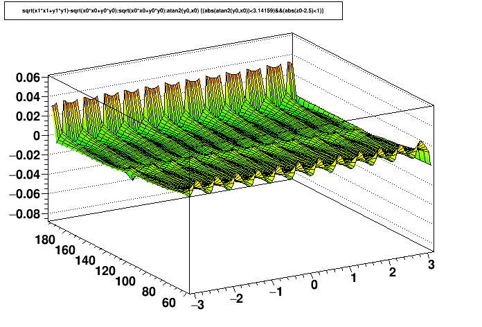
- Units: all axes on all distortion maps are [cm] except ratios.
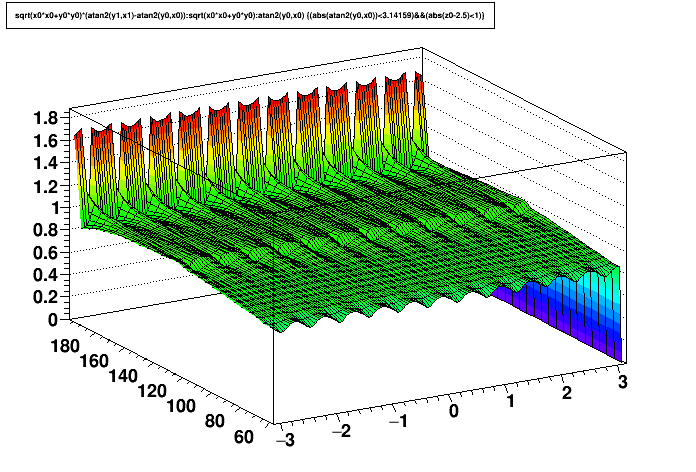
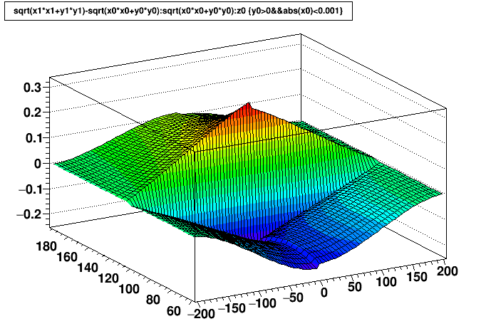
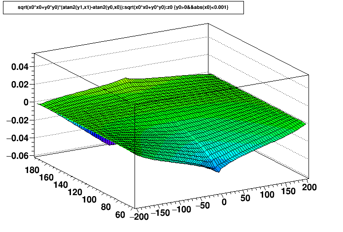
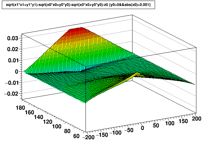
- Plots vs. z are calculated at φ=0 (middle of a sector).
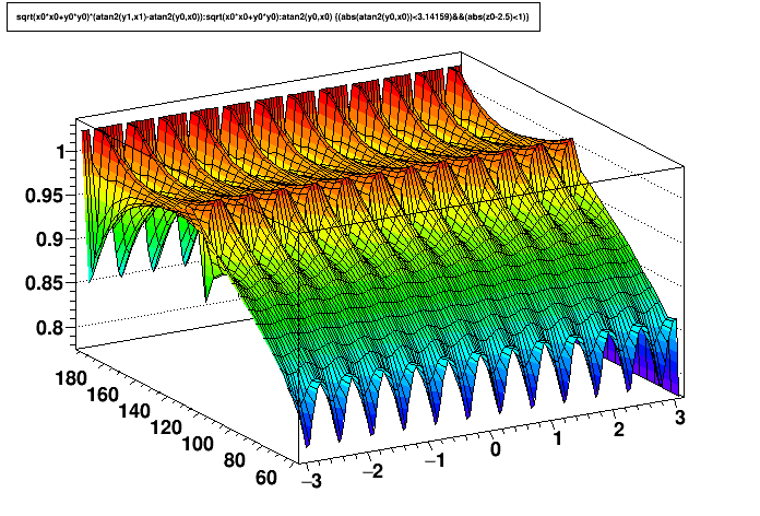
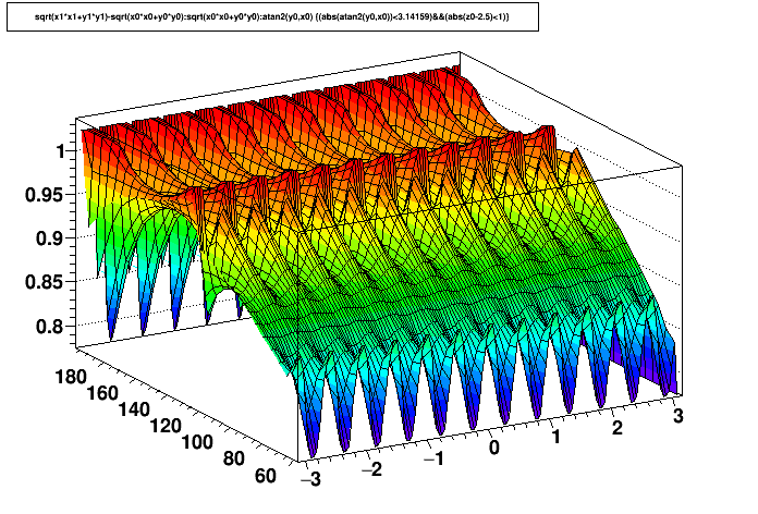
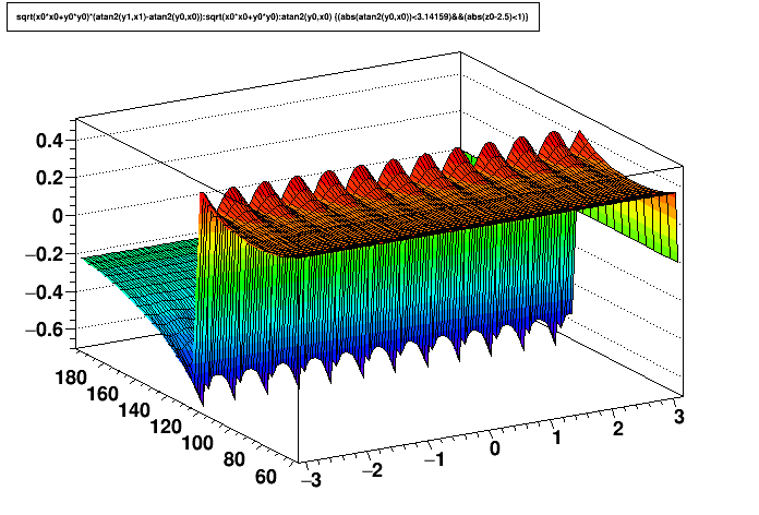
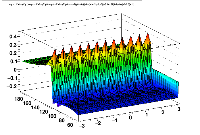
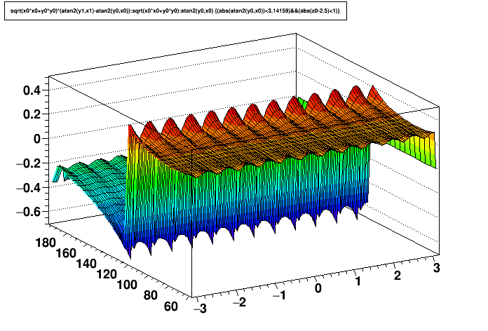
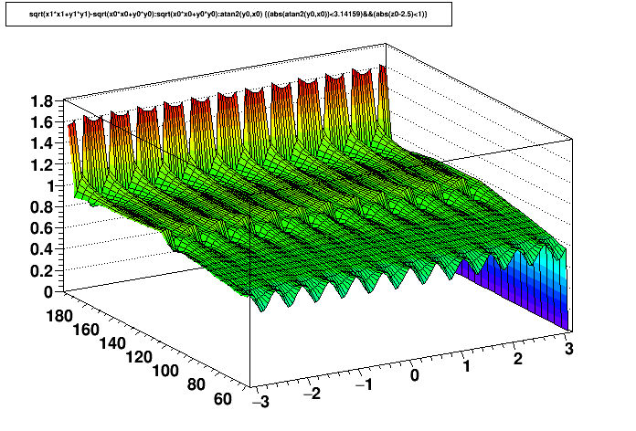
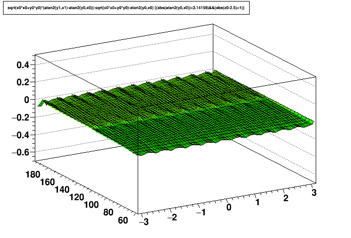
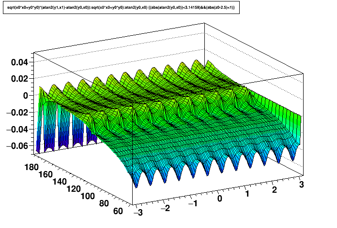
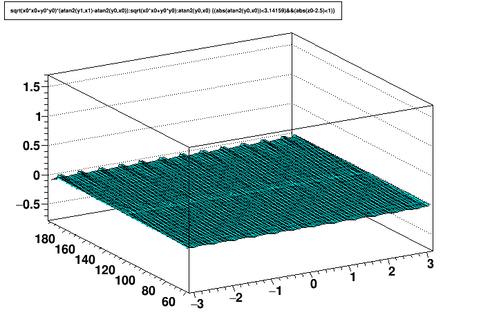
- Plots vs. φ are calculated at z=+2.5 cm.
- I calculated one radial bin at r=192.5, which is actually inside the outer charge sheet in the middle of the sectors (I used a local y of 191.49 cm for the inner edge of the outer charge sheet, which crosses r=192.5 cm at φ=±6° from the sector center, and a sector spans ±15° from its center).
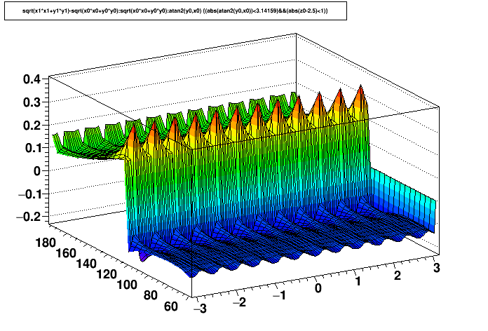
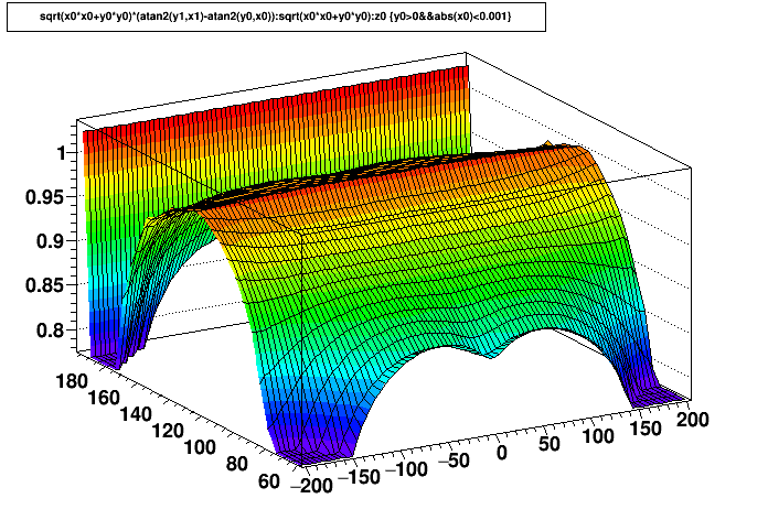
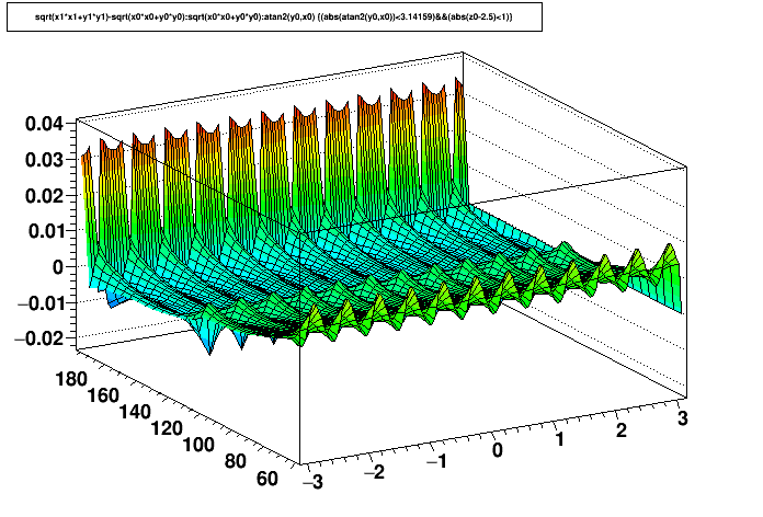
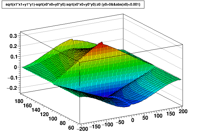
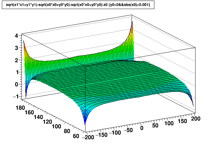
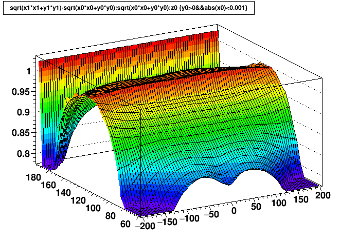
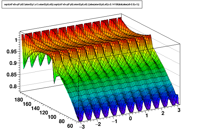
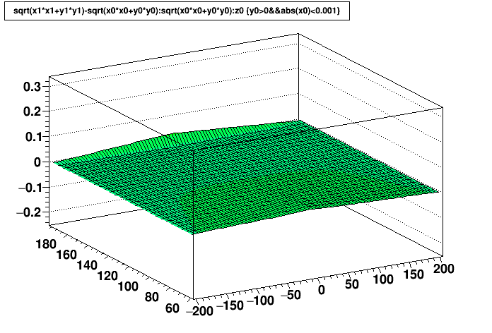
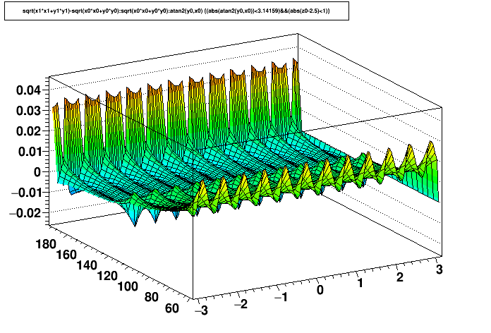
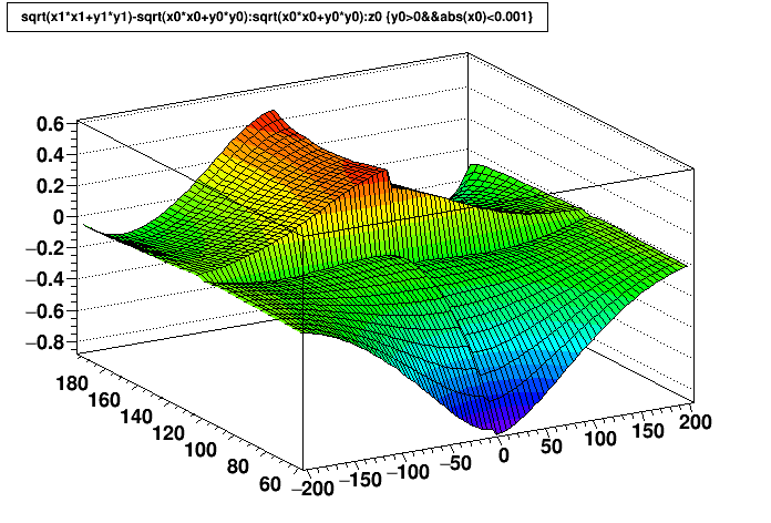
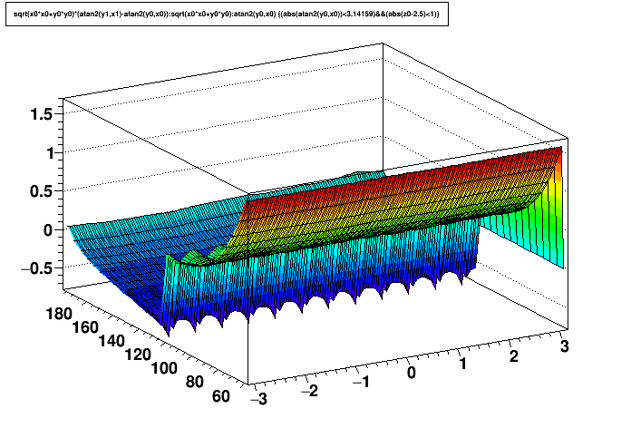
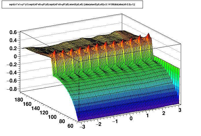
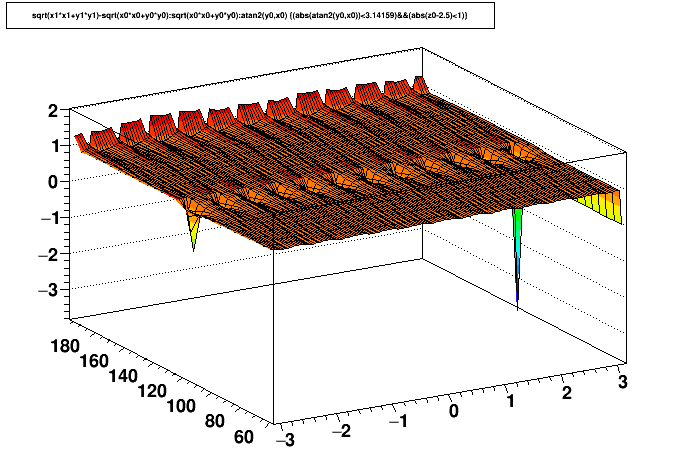
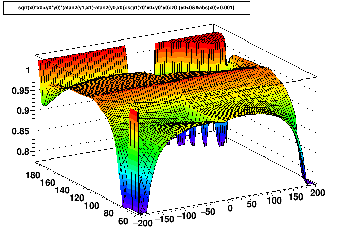
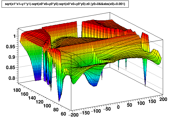
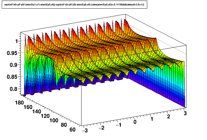
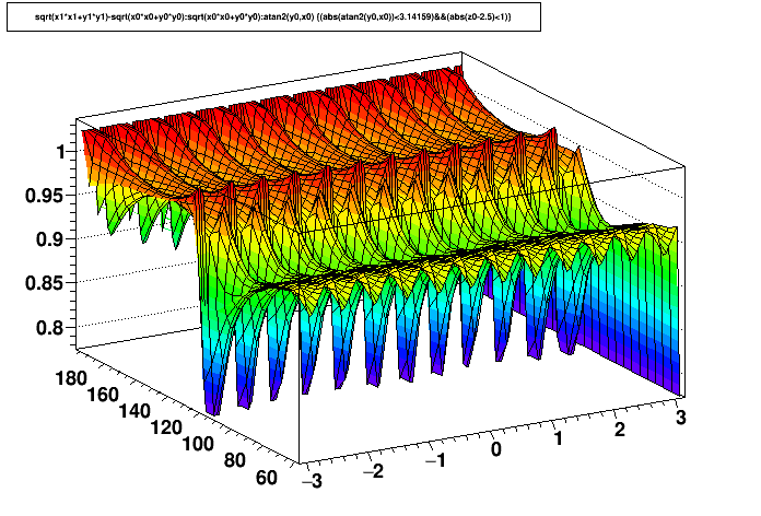
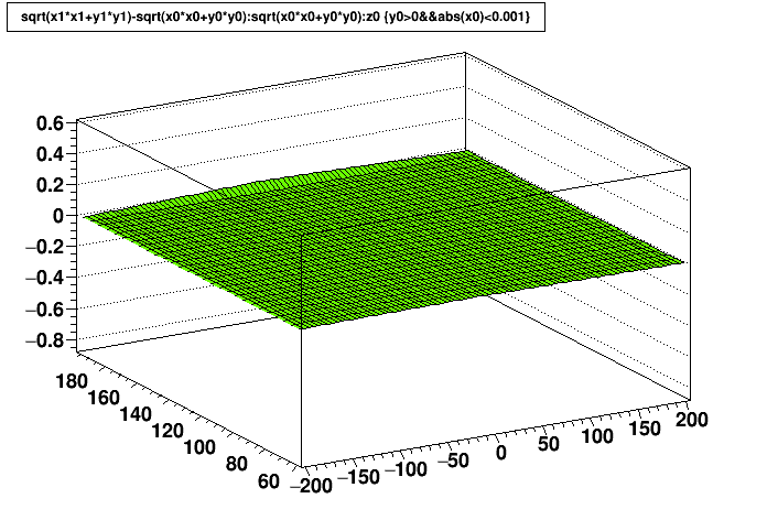
- Ratios of maps show large deviations from 1.0 when the distortion is small, so I have included both the ratios of maps and their differences.
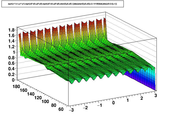
- Effects of both the inner & outer GridLeak are small, but noticeable.
- Taking into account all typical distortions doesn't change the above conclusion.
- Increasing inner HV from 1100 V to 1170 V increases middle GridLeak by 12.6%, and the inner GridLeak by 51%, but this is not enough to change the above conclusions.
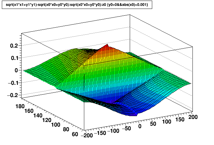
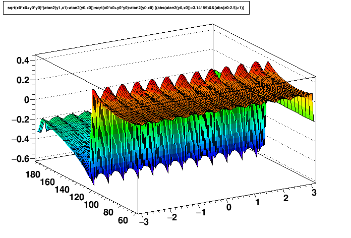
Test 1:
3D GridLeak distortion onlyInner HV @ 1100 V, Outer HV @ 1390 V (typical of recent operations)
| Δ(rφ) vs. z | Δ(r) vs. z | Δ(rφ) vs. φ | Δ(r) vs. φ | |
|---|---|---|---|---|
| Single GL | 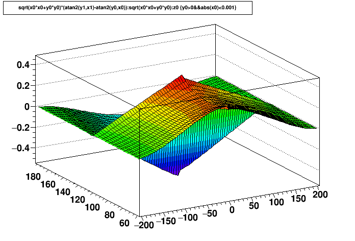 |
 |
 |
 |
| Triple GL | 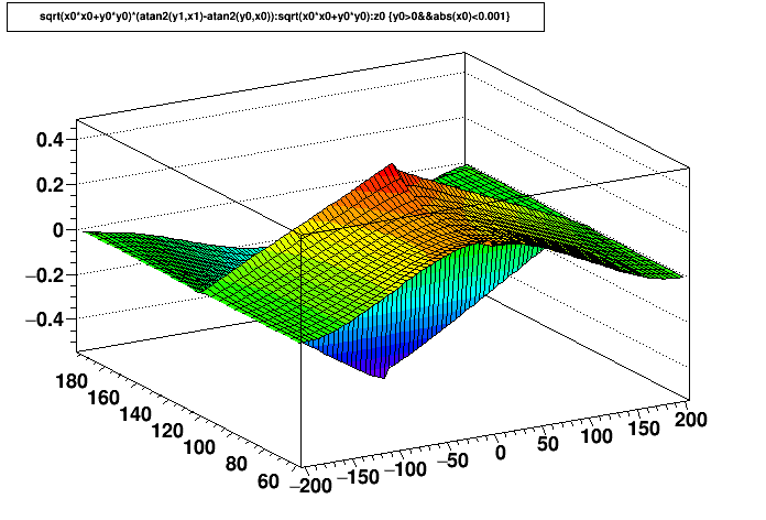 |
 |
 |
 |
| Triple/Single | 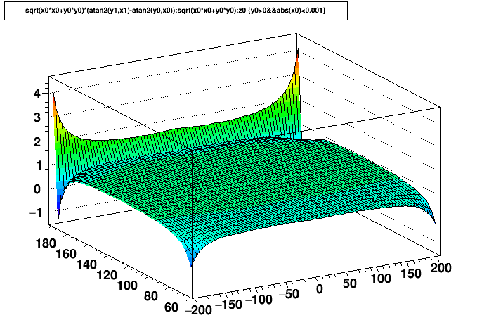 |
 |
 |
 |
| Triple/Single (zoomed in) |
 |
 |
 |
 |
| Triple - Single | 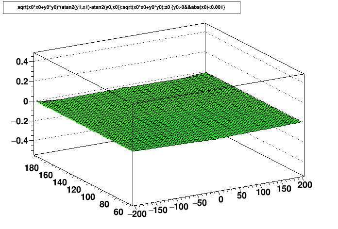 |
 |
 |
 |
| Triple - Single (zoomed in) |
 |
 |
 |
 |
Test 2:
3D GridLeak distortion onlyInner HV @ 1170 V, Outer HV @ 1390 V (nominal operating voltages)
| Δ(rφ) vs. z | Δ(r) vs. z | Δ(rφ) vs. φ | Δ(r) vs. φ | |
|---|---|---|---|---|
| Single GL |  |
 |
 |
 |
| Triple GL |  |
 |
 |
 |
| Triple/Single |  |
 |
 |
 |
| Triple/Single (zoomed in) |
 |
 |
 |
 |
| Triple - Single | 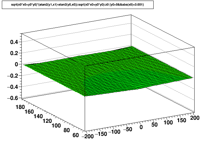 |
 |
 |
 |
| Triple - Single (zoomed in) |
 |
 |
 |
 |
Test 3:
All distortions: 3DGridLeak+SpaceCharge+PadRow13+IFCShift+ShortedRing+BField(3D)Inner HV @ 1100 V, Outer HV @ 1390 V (typical of recent operations)
| Δ(rφ) vs. z | Δ(r) vs. z | Δ(rφ) vs. φ | Δ(r) vs. φ | |
|---|---|---|---|---|
| Single GL |  |
 |
 |
 |
| Triple GL |  |
 |
 |
 |
| Triple/Single | 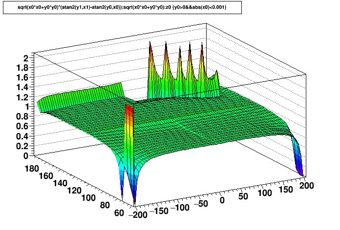 |
 |
 |
 |
| Triple/Single (zoomed in) |
 |
 |
 |
 |
| Triple - Single | 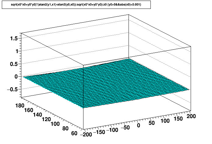 |
 |
 |
 |
| Triple - Single (zoomed in) |
 |
 |
 |
 |
-Gene
»
- genevb's blog
- Login or register to post comments