Works at the experimental hall for the FMS
Stevephen Trentalange, Steven Heppelmann and I have been working on the FMS trying to diagonois and repair some of the small cells. Here is a brief summary of the status.
1. A dipole magnetic field was found which seems to be consistant with the FMS gain changes when the STAR magnet orientation was flipped.
Stephen Trentalange to starfms-hn
show details Oct 14 (3 days ago)
Jingguo and I already tried sheets of the same shielding material
in use on the inner faces of the FMS enclosure. They seem to
cut the field by factors from 3 to 10. We need to make a
magnetic circuit, ie a 'return yoke' of soft iron sheet which will
cover the entire pump:
Top View
| |
| |
| XXXXXXX | Dipole
S | X PUMP X |North ------>
| XXXXXXX |
\______________/
Well, it is kind of hard to draw in ASCII, but you get the idea
that the dipole goes NorthSouth through the body of the pump,
perpendicular to the beamline. This means the field has large
components parallel to the beamline on either side of the pump.
These components do not reverse when we reverse the STAR magnetic
field, so they add either constructively or destructively in
opposite directions, causing a change in gain.
When we get the trigger working again, it might be possible to
examine the change in gain for LEDs with and without shielding,
with the FMS in the closed position.
Stephen
2. We tried to look at the individual channels that were either not giving data during run 9 or not working during this summer's LED test.
A. Fixed several channels.
North side
Channel 53, row4, col 4. HV mapped to dev1chip0chan2addE2, now on dev1chip0chan3addE8. Replaced Yale base. Observed LED. Fixed now
Channel 52, row4, col 3. Found base not plugged into pins. Observed LED. Fixed now
Channel 165, row13, col 8. Replaced PSU base. Observed LED. Fixed now
South side
Channel 187, row15, col 6. Replaced Yale base. Observed LED. Fixed now
Channel 105, row8, col 8. Replaced the cable from back panel to patch panel. Observed LED. Fixed now
B. Status and next steps

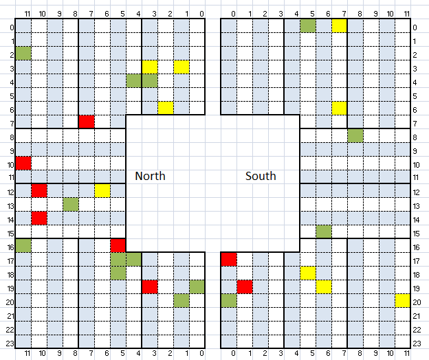
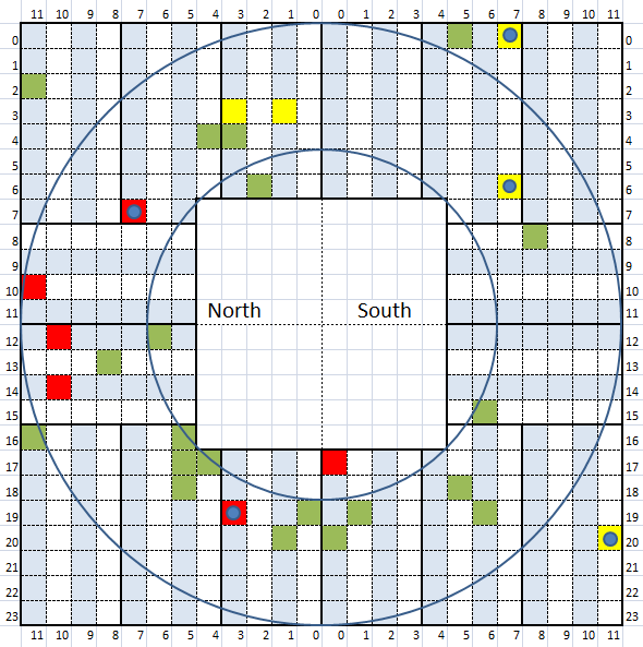
These highlighted cells are the ones that had problems either in run 9 or during the summer LED tests. Those in red are the bad ones found in run 9 that needs to be fixed and those in yellow are the ones found during this summer. Those in green are the ones that now looks ok (with reasonable LED signals).
Next we will continue testing and trying to fixed as many as we can (depends on whether we can get a hand on it).
We will use the trigger system for more testing when it comes back.
The HV control program seems to have some problem sometime. Some channel doesn't go to commanded HV, not sure how we can test it.
Update of the status on Oct. 25
1. Green ones are already fixed.
2. Red and yellow ones are the ones need to be fixed next.
3. Blue circle means identified bad tubes.

- jgma's blog
- Login or register to post comments
