- jwebb's home page
- Posts
- 2019
- 2018
- 2017
- 2016
- 2015
- 2014
- 2013
- November (1)
- October (1)
- September (1)
- July (1)
- June (1)
- April (1)
- March (3)
- February (1)
- January (1)
- 2012
- 2011
- December (2)
- September (3)
- August (5)
- July (6)
- June (6)
- May (1)
- April (5)
- March (5)
- February (2)
- January (2)
- 2010
- December (3)
- October (3)
- September (2)
- August (2)
- June (2)
- May (4)
- April (4)
- March (2)
- February (4)
- January (10)
- 2009
- 2008
- 2007
- 2006
- July (1)
- My blog
- Post new blog entry
- All blogs
Comparison of material in TPC at forward angles in between sector boundaries
There is an open question remaining with respect to the new version of the TPC geometry (TPCe04): should we use TPCe04 in geometries which prior to 2008? y2009a geometry status, take 2.
This improves the description of the TPC material at the sector boundaries at pseudorapidities appropriate for endcap analyses. However, it may degrade fidelity within the middle of the sectors where the material budget is smaller. The reason is that TPCe04 implements the TPX electronics,
which are distributed differently than the original readout boards.
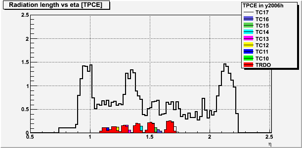
To quantify this, I generate geantinos in the range -10° < φ < 10°, and 0.75 < η < 2.25. The number of radiation lengths vs η, averaged over the specified range in φ is plotted for the TPC below.
Figure 1 -- Number of radiation lengths vs η for the old (TPCe03) geometry. The TPC readout electronics are in red.

Figure 2 -- Number of radiation lengths vs η for the new (TPCe04) geometry. The TPC readout electronics are in red. Cooling cables in other colors.

One immediately sees that there are several changes between the two geometries, not just the electronics boards. To shed some light on the tradeoffs, I plot the difference in radiation lengths vs eta for the TPC as a whole, and just the electronics (ignoring cooling).
Figure 3 -- Difference (old - new) vs eta for the full TPC (black histogram) and just the electronics (red histogram).
.png)
(1) From 1.1 < eta < 1.3 about 0.1 radiation lengths max is attributed to changes in the electronics. This is about 1/2 of the total difference.
(2) From 1.4 < eta < 1.7 about 0.2 radiation lengths max is attributed to changes in the electronics. This accounts for nearly all of the total difference, and likely all of it once cooling is accounted for.
(3) Above eta = 1.7, little if any of the total change is due to electronics. (<0.5 radiation lengths).
Groups:
- jwebb's blog
- Login or register to post comments
