- jwebb's home page
- Posts
- 2019
- 2018
- 2017
- 2016
- 2015
- 2014
- 2013
- November (1)
- October (1)
- September (1)
- July (1)
- June (1)
- April (1)
- March (3)
- February (1)
- January (1)
- 2012
- 2011
- December (2)
- September (3)
- August (5)
- July (6)
- June (6)
- May (1)
- April (5)
- March (5)
- February (2)
- January (2)
- 2010
- December (3)
- October (3)
- September (2)
- August (2)
- June (2)
- May (4)
- April (4)
- March (2)
- February (4)
- January (10)
- 2009
- 2008
- 2007
- 2006
- July (1)
- My blog
- Post new blog entry
- All blogs
Material budget in the (development) y2013 and y2014 geometries
The y2013 Geometry
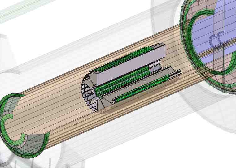
The HFT pixel detector is expected to be inserted in one of the so called "Mercedes" configurations. Active silicon layers will be present at roughly 120 degree spacing. However, the material budget should be approximately symmetric in phi because it is anticipated that passive material of approximately the same thickness will be placed where the other active layers would be.
Figure 1 -- Geometry tag y2013 illustrating the HFT.

Figure 2 -- Y2013 material budget, showing the number of radiation lengths presented by the inner detector support module and detectors within. The black line shows the material present inside of the IDSM. The yellow histogram shows the amount of material in the ladders, the dark green histogram shows the material in the active layers, the magenta shows the amount of material present due to the piston support tube, and the light green the FGT. This figure is averaged over a 30 degree slice in phi.
.png)
The y2014 Geometry
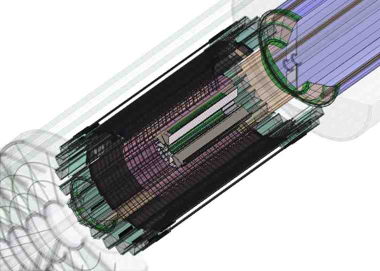
Figure 3 -- Full installation and addition of SSD and IST.

Figure 4 -- Y2014 material budget. material budget, showing the number of radiation lengths presented by the inner detector support module and detectors within. The black line shows the material present inside of the IDSM. The yellow histogram shows the amount of material in the ladders, the dark green histogram shows the material in the active layers, the magenta shows the amount of material present due to the piston support tube, and the light green the FGT. This figure is averaged over a 30 degree slice in phi. The increase in the IDSM relative to the y2013 geometry is due to the addition of the SSD and IST.
.png)
Figure 5 -- Y2014 material budget, broken down by major detector. PXMO is the pixel detector, SFMO is the SSD, IBMO is the IST and PSTM is the piston support tube for the HFT. (Note: the IST ends around eta = 1.3, and teh FGT begins around 1.3.)
.png)
The 2010 Geometry
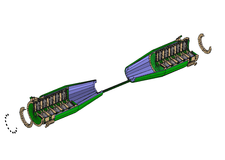
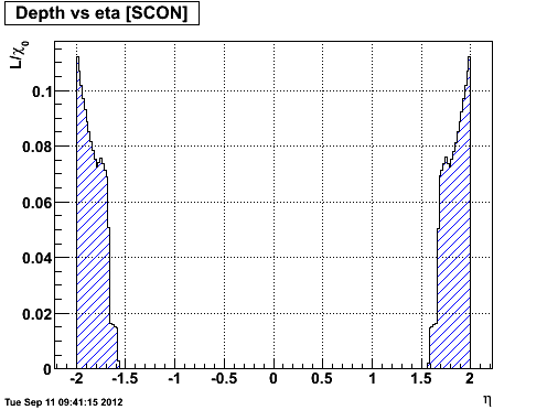
Geometry tag y2010a, sampled a 30 degree slice from 0 to 30 degrees over -2 < eta < 2. (Only the support cone is in the acceptance, and the support rods are not in the 30 degree slice).
Figure 6 -- Inner detector geometry in 2010 (y2010a tag). Right plot shows the material budget over 0° < phi < 30° and -2 < eta < 2.


- jwebb's blog
- Login or register to post comments
