- leun's home page
- Posts
- 2013
- 2012
- December (2)
- October (3)
- September (2)
- August (1)
- July (4)
- June (4)
- May (2)
- April (3)
- March (5)
- February (5)
- January (5)
- 2011
- December (3)
- November (3)
- September (5)
- August (2)
- July (2)
- June (3)
- May (4)
- April (4)
- March (2)
- February (4)
- January (2)
- 2010
- December (2)
- November (3)
- October (3)
- September (5)
- August (6)
- July (2)
- June (4)
- May (3)
- April (4)
- March (4)
- February (2)
- January (4)
- 2009
- 2008
- October (1)
- My blog
- Post new blog entry
- All blogs
FMS Small Cells HV
There are two different types of high voltage bases used for FMS small cells, one designed at Penn State and another that came from Yale. While both types use the same 8-bit digital pot (Analog Devices AD5259) to control the HV, they have different DAC-to-HV ratio.
Penn State Base
The formula for predicting the high voltage as a function of input DAC value is the following.
.gif)
RDAC = 8-bit integer (in Hex) one inputs in the "console" control script.
NDinode = 22
N1stStage = 3
R0 = 2.7M ohms
R1 = 120K ohms
R2 = 50K ohms
Vdiode = ~0.8V
CF = correction factor, can range from 0.7 to 1.3. (More on this later)
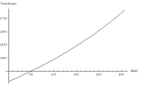
For CF = 1, we get the following graph.


The mild non-linearity is a design feature due to the limited selections of digital pots that met other design considerations at that time.
The correction factor accounts for the variation in overall resistance of the the digital pot. While base-to-base variation in the HV due to this can be in principal as large as ~15%, the precise value of the resistance variation from the nominal value is stored in the chip itself. This gets read in automatically by the "console" script that controls the HV system. Therefore when one sets the HV with the script, the "predicted" HV value that gets printed out already accounts for this variation. The same is true for the output of commands like Checkall 3 and 4.
There are no other sources of significant base-to-base HV variation that we are aware of.
Yale Base
Yale base (Nanometric base) is trickier, since we only designed the control board that supplies the analog "control" voltage. We tested every base for functionality, but we do not have the data on the base-by-base HV variation given fixed control voltage. The base itself has a feedback circuitry that dynamically matches the HV to the control voltage.
The formula for predicting the high voltage as a function of input DAC valuse is the following.
G is supposed to be 200 for these bases according to the original design. The uncertainty in this parameter is the main limitation in understanding the Yale bases.
R0 = 255K ohms
R1 = 40K ohms
R2 = 50K ohms
Correction factor is the same as before. But because R2:R1 ratio is now larger, the effect of the correction factor is bigger, and can cause variation in HV by ~20%. But again, the control script takes this into account by reading in individual variances, and one can reasonably rely on the predicted value calculated by the script to set the HV.
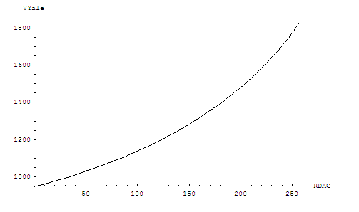
For correction factor of 1, we get the following dependence.
By far the largest uncertainty in base-to-base HV comes from the variation in the digital pot, but this is taken into account by the control script that reads in the variances from individual chips and applies them in calculating the predicted voltages. While we've found that the absolute value of the predicted voltage can still be a few percent off from the HV read out, considering that the non-linearity over the operating range is fairly mild, one can reliably use the script to determine the relative change in HV.
- leun's blog
- Login or register to post comments


