- leun's home page
- Posts
- 2013
- 2012
- December (2)
- October (3)
- September (2)
- August (1)
- July (4)
- June (4)
- May (2)
- April (3)
- March (5)
- February (5)
- January (5)
- 2011
- December (3)
- November (3)
- September (5)
- August (2)
- July (2)
- June (3)
- May (4)
- April (4)
- March (2)
- February (4)
- January (2)
- 2010
- December (2)
- November (3)
- October (3)
- September (5)
- August (6)
- July (2)
- June (4)
- May (3)
- April (4)
- March (4)
- February (2)
- January (4)
- 2009
- 2008
- October (1)
- My blog
- Post new blog entry
- All blogs
Lambda hyperon proton pi- channel
In this page, I've looked at what the minimum requirement would be to perform displaced vertex cut on a 40 GeV Lmabda hyperon, assuming we have two charged particle detection layers (such as Alex's HALO + Preshower in front of the FCS/FMS) at z=410cm and 710cm.
First, I looked at Pythia event record (sqrt(s)=200GeV) for the density of electron/positron, pion, and proton hits at z=410cm as a function of pseudo-rapidity.
Fig. 1. Charged particle hit density (per d_eta=0.1 and d_phi=30 degree slices)
.gif)
Clearly, the hit density for a typical event at 200GeV is fairly low. But this will very much depend on the structure of the particular type of events we are interested in.
Now we look at the displaced vertex distribution for charged hadrons with E>30GeV.
Fig. 2. Pythia (200 GeV) vertex distribution for charged hadrons with E>30GeV, for the Lambda (Red) vs. all other (Black)
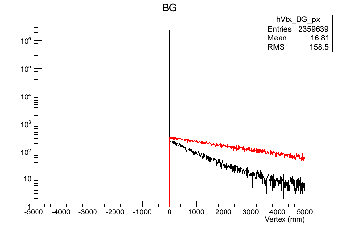
Notice that in this plot the X-axis in in millimeters. It's clear that displaced vertex cut would be very effective for Lambda reconstruction.
Fig. 3. Fraction of the Lambda events with E>40GeV with vertex > V(x)
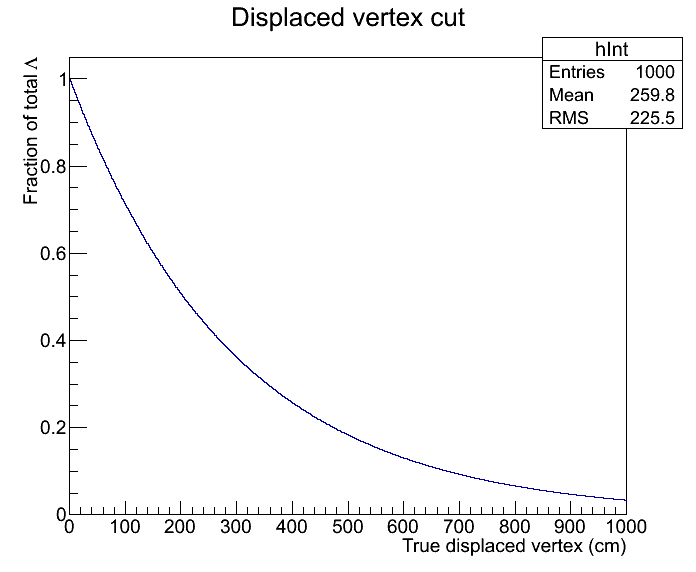
So if we cut at Vertex > 1m, we can keep ~70% of the signal while suppressing background significantly.
The problem is that the opening angle for the Lambda decay is very small, and this very much makes the low hit density meaningless as far as lambda reconstruction is concerned.
Fig. 4. Track separation at the first layer as a function of the true displaced vertex, 40 GeV Lambdas.
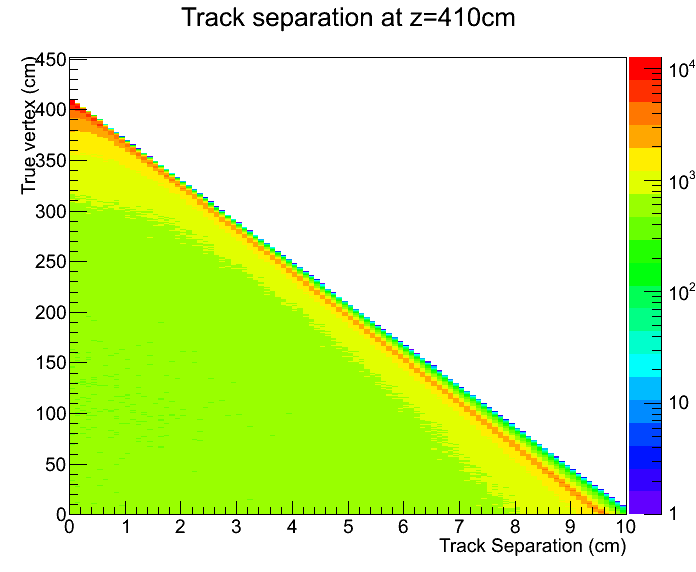
Roughly speaking, the maximum opening angle is ~1/(lambda energy in GeV) in radian.
In order to estimate the vertex reconstruction resolution using two planes, I ran a toy MC, with planes located at 410cm and 710cm. Thrown lambdas had energy of 40 GeV, and uniform pseudo-rapidity distribution between 2.2 and 4.3. For each plane, the pixel size was varied from 0.1cm to 1cm in 0.3cm steps. In reality this just means I applied flat smearing of half the cell width to the X and Y coordinates of the track, and then reconstructed the two tracks from the smeared coordinates and calculated the DCA and the "pair vertex".
Fig. 5. True vertex vs. Measured vertex for varying resolution for the two planes
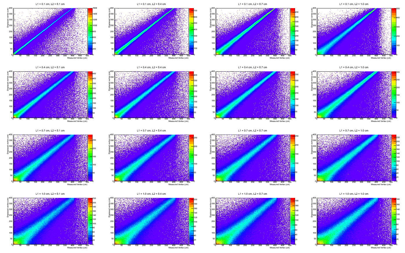
For instance, if we were to do Vmesured >100 cm cut, for L1=1cm, we see that the true vertex distribution for these events are not sufficiently away from zero.
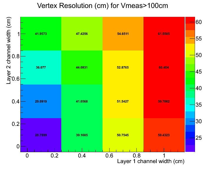
The RMS for each distribution, only for the events with measured vertex > 100 cm, is shown below.
Fig. 6. Vertex resolution for varying cell width for the two planes, measured vertex > 100 cm.
Another potential problem is background tracks producing smaller DCA than the correct pairs, resulting in the loss of signal. I've made a simple modification to my toy MC to take a rough measure of how bad this effect might be, as described below.
1. For each event with measured lambda vertex > 100 cm, produce up to 10 extra tracks, all originating from the primary vertex. Pseudo-rapidity of these tracks are within +-0.2 of the lambda, and phi is randomized.
2. Smear and reconstruct these tracks the same way the lambda daughter tracks are handled.
3. For each extra track, pair it with the two lambda daughter tracks. If the resulting pair vertex is larger than 100 cm, divide the correct DCA by this background DCA. This is my ratio.
4. The extra tracks are not paired among themselves. This is an obvious omission, but it is unlikely that these extra primary tracks would survive the requirement that the pair vertex be larger than 100 cm.
So in the follwing plot, if the Y value is great than 1, that means we will have an incorrect pairing. If less than 1, then the correct lambda pair will survive. We expect the mispairing to get worse as the number of extra tracks increase, as the ratio for the minimum background DCA is plotted.
Fig. 7. Lambda vertex DCA / background DCA vs. Number of extra primary tracks
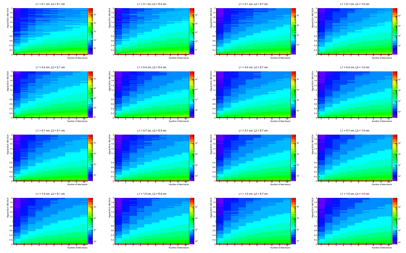
The reason for the pile up at y=0 is the requirement that the pair vertex be larger than 100 cm. It is clear that even with 10 primary tracks within +-0.2 of the lambda pseudo rapidity, the fraction of event that would result in incorrect pairing is extremely small, at least in this simple simulation. This is likely due to the fact that the true lambda daughter tracks have very small opening angle.
- leun's blog
- Login or register to post comments
