FGT HV Testing and Software Development - Oct 2011 visit to BNL
Notable tasks completed this week at BNL
- Get second crate up and running
- SPLIT test system and real system EPICS configuration
- Setup to display FEE temp information from Tonko
- Implement graphical HV monitor (experts screen)
- Meet with Dilan to discuss Logs/Alarms/general EPICS
- Meet with David Dudley about EPICS implementation for gas system monitor. MODBUS, possibly with ADAM device
- Meet with Andreas to address problems with system behavior
- Automatically set groupsSwitch.64 to 5 for proper trip!
- Exercise HV trip to insure proper behavior
Some things still on the to-do list
- Integrate with STAR archiver and alarms
- Move EPICS softIOC to iocsys1.starp.bnl.gov (or some such system)
- Implement some minimal logging for local test setup
- Address random readback from supplies (job for Wiener/iSeg)
Current HV control screen:
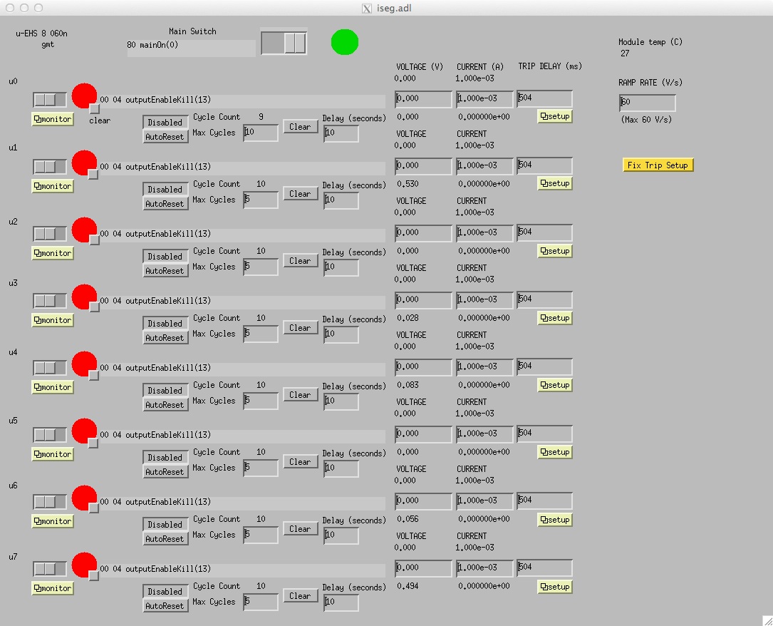
Note the addition of a "monitor" button. This will open a new display window which will give you a simple graph of the voltage and current for the channel. See below.
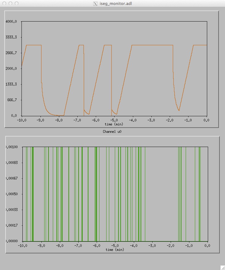
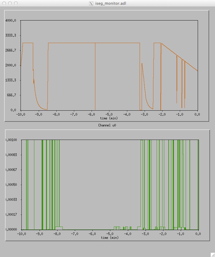
The following graph show the "monitor" screen. This plot illustrated the frequency at which we get bad current values from the system. Typically the voltage value is reported when the software requests current. Andreas was able to reproduce this with another control system. He will take that up with the engineers.
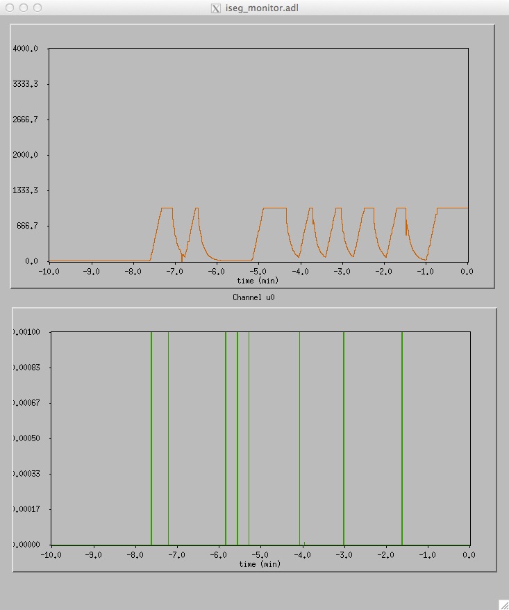
This illustrates the cycling of the Auto-Reset feature with a 10 second delay. Note that there is nothing connected to the supply at this time. The discharging of the internal capacatance is about what we expect. The trip was drawn by setting the maximum current to zero.
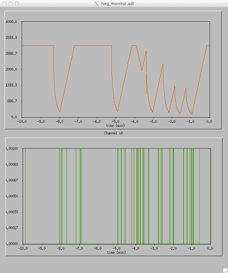
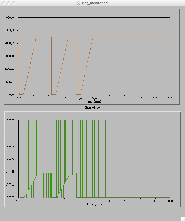
Trip testing with Gerard's test load designed to draw a single trip with a variable pulse time. You can see several trips here. The supply responds properly by shutting down the channels. Some trips were done at 3000 volts. Some are as the HV was ramping up.
Here we have set the supply in an improper mode - Ramp Down After Trip. In the final trip sequence you can see that we tried to draw trips several times as it was ramping down. This is not the setting we want. It is also the default configuration when the supply is powered on. A spark to ground was able to trip the supply as seen at about t=-3 min. We did not see any quick restart behavior from the supply as had been hinted at earlier.
Also note that in this trip mode we were able to ramp the supply voltage up at 1200 V/s. With tripping enabled, the maximum ramp rate is 60 V/s.
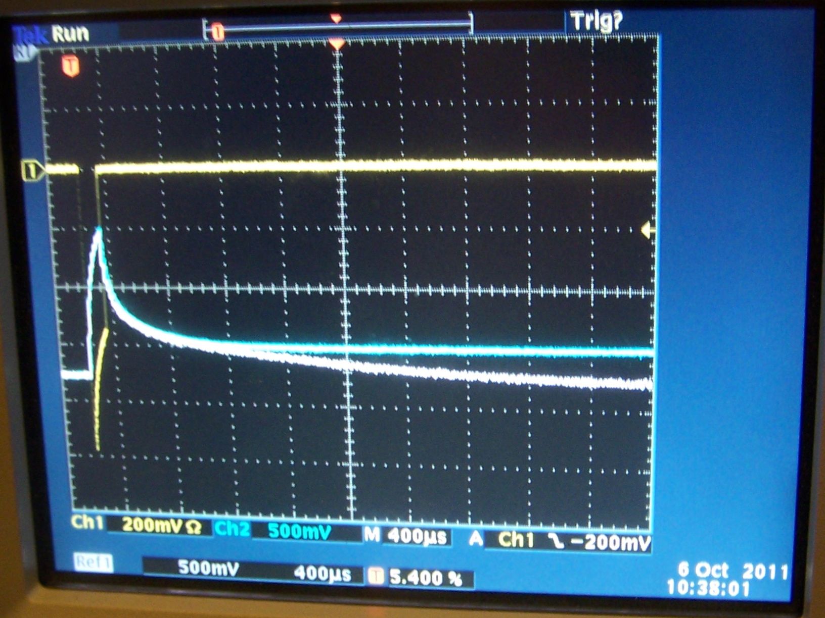
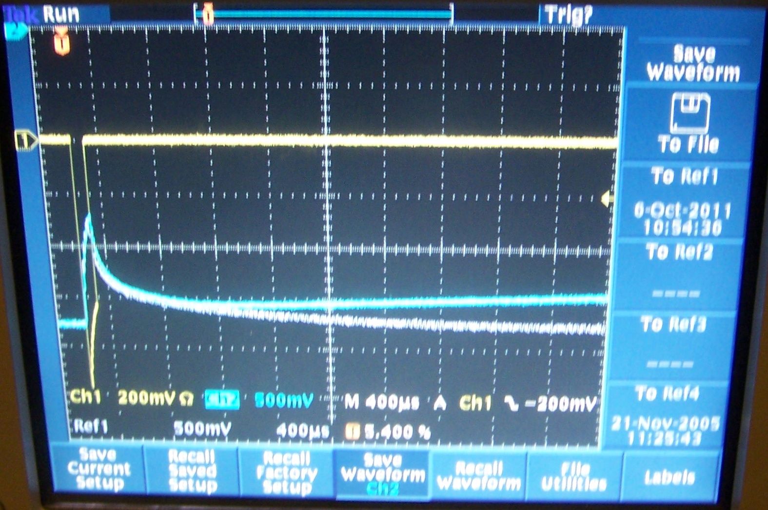
Small current draw here comes from Gerard's HV probe which was used to monitor the system with an oscilloscope.
Tests were repeated with one of the HV boards connected to the system. Here you see a DC current level drawn by the board as we ramp up. With the additional load you can see that any remaining voltage is quickly discharged.
Oscilloscope traces of the voltage and current which trips the HV supplies. Voltage and current are negative. The top trace is the current. You can see the quick spike through our test assembly. On the bottom are two traces from different trips. The length of the current pulse is slightly different. The trace closer to the top is the longer pulse which trips the supply. The slightly shorter pulse does not trip the supply. You can see here that the supply trips somewhere around 500 µs after the pulse. Voltage shutdown on this time scale is a very small difference. On the lower voltage trace the voltage quickly recoveres - within a few ms.
- pnord's blog
- Login or register to post comments