Checking EPD QTC -> DSM
Since we moved many of the QTCs around, we need to move the QT adapter cards in the back so that the QTCs are connected to the DSMs. All East QTCs should go to EP001, all west QTCs should go to EP002.
There are 2 QTCs that are still lined up with an adapter car: EQ1 0x1A and EQ2 0x1A
Eleanor sent some instructions, which can be found at: drupal.star.bnl.gov/STAR/system/files/EleanorIns03222023.txt
First, one needs to be ready to run remotely (if not in the control room). Follow the instructions at: drupal.star.bnl.gov/STAR/blog/rjreed/Running-EPD-Remotely
My annotated instructions below:
a) Power on EQ1 (as well as L01, etc...) or whatever EQ one is looking at. Needs the BBC crate as well.
b) Login to startrg.starp.bnl.gov by ssh -A staruser@startrg.starp.bnl.gov
c) telnet eq1.trg.bnl.local
Caution!!! Up arrow doesn't work. CTRL+X will reboot and that takes a long time to come back. It doesn't like delete.
d) Launch Run Control
e) Start a run with 0 events
f) Wait until configuration is complete. The TRG box on the Run Control GUI should be yellow,
g) In the eq1 window use "m" to write the value 0x10 to address 0x10fc4030
The "m" means modify. With 0x10fc4030 we are addressing the 4th daughter card in the board in the 0x10 slot. (Which is a QTC in this case, though not connected to the DSM right now.) These are 4-byte addresses, so the actual command should be:
m 0x10fc4030,4
Then one should see all 0s. Then to put in the ramp command, type 10 and hit enter. It will go to the next address, which we don't want to do anything with. So type . and hit Enter to exit.
To check, one should type:
m 0x10fc4030,4
Then it should be 000010
Exit by typing . and hitting Enter again. Now we are ready for the next part of Eleanor's instructions.
h) Back to the Run Control GUI. Issue however many triggers you want.
i) Stop Run
j) Look at the data file. You should see lots of data in one channel of EP001. Please make a note of which channel has the data.
This means to go to the run log, and look at the L0 trigger pdf that is being generated. (Under daq info in the Run summary.) Go to EPD L0 Input. Right now there are a lot of "red" high boxes, because the QTCs are not connected to the DSMs and float high. An example is:

j) In the eq1 window use "m" to write the value 0x0 to address 0x10fc4030. This turns off that ramp and you are done with this QTC.
so:
m 0x10fc4030,4
0
.
then check with:
m 0x10fc4030,4
Should only display 0s. Then . to exit.
Then one can check the next board. In the case of EQ1, that would then be:
m 0x18fc4030,4
The distribution of the boards within the crate can be found at: drupal.star.bnl.gov/STAR/system/files/userfiles/1108/VME_09112022.png
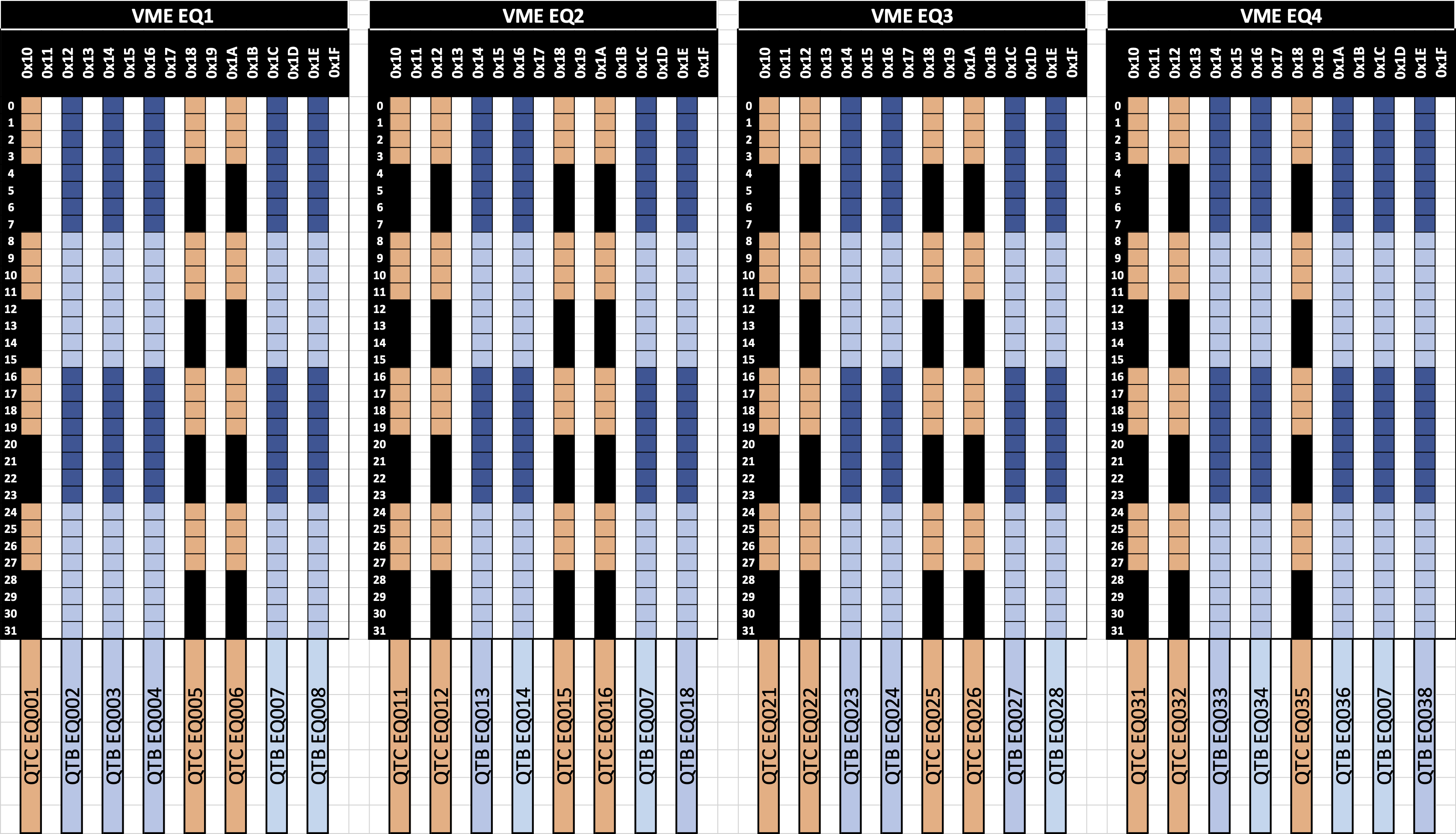
To exit, one must use the command:
logout
Remember to turn off the VME crates if no one is sitting in the Control Room!!
The details of what we are supposed to do from Eleanor's email are:
EQ4: drupal.star.bnl.gov/STAR/system/files/PXL_20230317_140912382%281%29.jpg
EQ2: drupal.star.bnl.gov/STAR/system/files/PXL_20230317_140803342%282%29.jpg
- rjreed's blog
- Login or register to post comments