Barrel Calorimeter: Tower power distribution box repairs
Note: See file attachment report in MS DOCX format
|
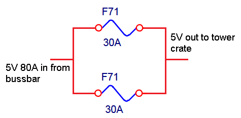
The original box design used 2x 30Amp automotive cartridge fuses connected in parallel (figure 1).
|
Figure SEQ Figure \* ARABIC 1 Parallel fuse arrangement |
|
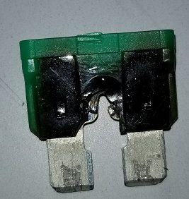
Connecting two separate fuses in parallel to make a larger fuse is not acceptable practice and is prohibited by NEC article 240.8. This led to routine overheating of fuses and fuse holders (figure 2). It also caused excessive heat to build up inside the enclosure and to deal with the excessive heat, fans were added to the box.
|
Figure SEQ Figure \* ARABIC 2 Burnt fuse removed from power distribution box |
After the system was in service for over ten years. The question was posed to me as to why the fuse and sockets were overheating.
My observations were as follows in 2010:
Parallel fuses:
I informed the experiment that the reason for the melted and overheated fuse sockets were caused by the paralleling of the fuses. There exists an imbalance where one fuse will gradually see its share of the load current increase and thus the fuse, socket and connection will run hot and then in time the fuse may open. This is because there is no guarantee that both fuse and socket pairs are exactly matched…hence the first part of NEC 240.8.
Incorrect addition of cooling fans:
At some point fans were added inside of the distribution boxes. The distribution boxes are not active devices and as such should not see an excessive rise in temperature. In comparison, for most circuit breaker panels a 60˚C rise over ambient is the maximum allowed. It seemed evident by the melted fuse, sockets and burnt connections, that the fuse and socket connections were exceeding a 60˚C rise.
I commented that the addition of fans would be a similar scenario if an Electrician placed a fan in your homes breaker panel if it were getting too hot.
Repairs to the Power Distribution Boxes:
We had to routinely replace melted fuses during and after each collider run. We also had to replace several melted fuse holders and burnt wiring. To correctly repair (not just replace existing fuse and holders) and to remedy the overheating problem and conditions that were causing it, I suggested that we replace the fuse and socket to appropriately rated part numbers. This would not be a modification to the original design but a repair using the correct parts.
|
Part number |
Description |
|
|
FHJC1002G |
FUSE HOLDER BLADE 58V 60A IN LINE, Littelfuse |
|
|
0895050.Z |
Fuse 50A, cartridge |
|
|
|
|
|
This arrangement mitigated the problem with melted fuses, fuse holders and burnt connections. However, just as in the original implementation, there could be a scenario where one of the 12AWG conductors becomes inadvertently disconnected. The remaining conductor is now inadequately protected by the 50Amp fuse as per article 310. In this scenario for this cable, the maximum current capacity is reduced to 30Amps.
Without an almost complete re-design of the distribution system, we could place individual fuses to protect each of the 2x conductors (figure #). However, this would put us back to the original problem with fuses in parallel.
Looking at NEC article 310.10U:
With the single 60A fuse and 2x 12AWG wires tied at the splice, we meet exception 1(a).
If we place fuses on each individual 12 AWG wire, we meet 1(a) and 1(c) but not 1(b). but the original issue still may occur.
310.10Uses Permitted.
1)General. Aluminum, copper-clad aluminum, or copper conductors, for each phase, polarity, neutral, or grounded circuit shall be permitted to be connected in parallel (electrically joined at both ends) only in sizes 1/0 AWG and larger where installed in accordance with 310.10(H)(2) through (H)(6).
Exception No. 1: Conductors in sizes smaller than 1/0 AWG shall be permitted to be run in parallel to supply control power to indicating instruments, contactors, relays, solenoids, and similar control devices, or for frequencies of 360 Hz and higher, provided all of the following apply:
1.
(a)They are contained within the same raceway or cable.
(b)The ampacity of each individual conductor is sufficient to carry the entire load current shared by the parallel conductors.
(c)The overcurrent protection is such that the ampacity of each individual conductor will not be exceeded if one or more of the parallel conductors become inadvertently disconnected.
Existing power cable:
The power from the distribution box and card crate are made with 12/4 (4 pair 12AWG) cable. To increase the ampacity of the cable, 2x pairs are connected (2x positive, 2x return).
The typical load current for the 5V supply is ~ 40Amps. The combination of the 2x 12AWG wires will have an equivalent rating of a 9-AWG conductor. The 12/4 cable (PN: M3868) is derated for 90˚C and with 2x conductors tied together, it is determined to be adequate for the load as per NEC article 310.
References:
M3386.12/4 cable. https://www.omotronic-mw.com/pdf-18/M3868-BK005.pdf
NEC 240.8 Fuses or Circuit Breakers in Parallel.
Fuses and circuit breakers shall be permitted to be connected in parallel where they are factory assembled in parallel and listed as a unit. Individual fuses, circuit breakers, or combinations thereof shall not otherwise be connected in parallel.
- timcam's blog
- Login or register to post comments