FCS LED controller user manual *DEPRICATED
FCS LED SYSTEM CONTROLLER
Software Control User Interface Rev 3
Use new application stored on LED box controller: ./led_sok3
Refer to updated software control manual from Jan/2022
Revisions: 1-3:
1- corrections/ typos
2- uploaded set_bias2 to ECAL box
3 - 11/16/2021 read / write mode option (section 1.0)
4 - 11/22/2021: added section 4: remote socket client connection
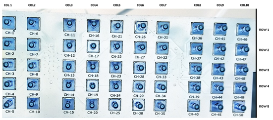
The output signals are arranged in a matrix of 5x rows and 10x columns.
For ECAL: Login to: ssh led@fcs-led1.starp.bnl.gov “130.199.60.245”
For HCAL: Login to: ssh led@fcs-led2.starp.bnl.gov “130.199.60.250”
user: led
pass: see PDF for PW
Working Directory -> cd\ documents
1.LED OUTPUT SELECTION
The python script “led_control.py” sets which channels are active.
Columns and rows are arranged as binary value
Command line options:
-m => set mode: => 0 = read, 1 = write
-r => DEC 0 to 31
-c => DEC 0 to 1023
31 = all rows on
1023 = all columns on
row 1 = low bit
col 1 = low bit
For example: To set all LED’s in column # 3 active (ch 11 – 15) type:
python3 led_control.py -m 1 -r 31 -c 4
For example: To turn on column 1 and column 2 all rows (ch 1 – ch 10) type:
python3 led_control.py -m 1 -r 31 -c 3
Note: Rows = 25 Columns = 210
Read only => python3 led_control.py -m 0
-> Response
read mode : 0
Reading output state for rows and columns, mode == 0
GPIO state of row pins: 011111
GPIO state of col pins: 1111111111
II. Led Voltage Bias: 12 Bit DAC: see note for ./set_bias2 updated application 02/17/2021
If running ./set_bias => old version
Voltage bias level has 2x groups of channels:
Ch’s 1 - 25 are BIAS 1 -> ID 96
Ch’s 26 - 50 are BIAS 2 -> ID 97
Type in:> “./ set_bias”
Then enter the ID (96 or 97) and DAC voltage in decimal
II.1 DAC value to voltage scaling:
The full-scale output is (30V / 4095) -> 7.3mv resolution
Example: To set a bias of 15V-> DAC value = 2048
02/17/2021: Updated bias setting -> ./set_bias2
To run set_bias2 just need to run application and enter the decimal bias value -> ./set_bias2 ####
III. Test Pulse
The control pulse is automatically selected from either the back LEMO input labeled “Trigger 2” or from an internal generated pulse from the SBC.
External Pulse Parameters:
-TTL Level 2.5V – 5V
-Pulse width at-least ~100ns
-Frequency 0 to 10kHz
Note: LED Controller Box: “fcs-led1.starp.bnl.gov” repeats the TCD trigger pulse to LED Controller Box “fcs-led2.starp.bnl.gov”
III.1 Setting Internal Pulse
Type:> python3 pulse_out.py
When prompted enter the pulse width in ms. & frequency in hertz:
Valid input is .1 to 999ms and 0 to 10000 Hz
Next enter the number of pulses to send:
IV Listening sockets on:
ECAL
130.199.60.245: 4001
HCAL
130.199.60.250: 4001
Usage:
- READ COMMAND
From the client, i.e. telnet session: “r” => read
A read displays the status and returns:
row/ column selection, LED voltage amplitude and self pulsing state.
The client just sends an “r” =>
Server sends back=>
row Bits 63 !
column Bits 1023 !
pulser freq. 0 !
DAC Value 2047 !
LED Voltage 15.00 !
DAC2 Value 2047 !
LED2 Voltage 15.00 !
- WRITE VALUES
Write command => w r# c# LED_voltage #
Example: set all rows/ columns on, with an LED voltage of 15.50 volts
=> w 63 1023 15.00
Voltage amplitude => increments of 1/100 of a volt
- SELF PULSER MODE => p frequency_in_Hertz
Example, set self-pulsing mode to 1000 Hz => p 1000
Note: setting frequency “p 0” tuns off self-pulsing mode
- timcam's blog
- Login or register to post comments