Gated Grid Driver II issues from run19
Background:
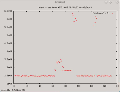
In preparation for run 19, an issue with large noise spikes were appearing in the TPC data. The occurrences were sporadic and would last for several minutes. Sometimes several hours would pass without the issue occurring.
....................................................
 .............
...........Image:1 Events recorded from DAQ system "Noise in TPC"
Although the new Gated Grid System (GGD II) operated well during run 18 without any noted incidence, we investigated the possibility that this oddity could be coming from the new system.
Any discrepancies or significant a-symmetries in the output to the gated grid wire pairs could cause this issue.
Since the issue was intermittent, examining the suspect boards related to the suspect channel(s) did not reveal anything.
We then became convinced that something must be breaking down or some anomaly was occurring intermittently somewhere in the new GGII system.
The crate and LV power supply for the driver/controller boards were replaced prior to taking data for run 19 but the issue remained.
Investigating the problem:
In order to narrow the problem down to the GGDII system, we connected the legacy driver and controller crates back into the TPC. After this the issue was not noted.
I now had to determine what in the new system was causing this intermittent blast of noise in the TPC. Certainly, if the driver circuit was failing intermittently and causing an imbalance in the output pulse, the TPC electronics would see this as large noise spikes.
However, since the problem was intermittent, catching the problem and the offending board would be very time consuming.
Remote oscilloscope and TPC DAQ:
After discussing the problem with Jeff, we decided we can use the TPC Data Acquisition System to see if we could catch the offending board in the act.
We setup a network oscilloscope at the experiment and patched into the gated-grid channels that had the most prevalent noise.
Jeff then configured the DAQ system to capture the TPC data in a slow acquisition (1 Hz).
I made a Python script that would set the oscilloscope to capture waveforms of the GGD channel every 10 seconds. The waveforms were time stamped so we could correlate ~ when the waveform was taken Vs the event captured in the DAQ.
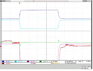
An offending board was discovered connected to Sector-13 and was in-fact a failure occurring during the output switching of the GGD differential signal (image 2). During normal operation the GGD generates a 75V square wave into the gate grid wire pairs for the respective sector. Looking at the scope captures relating the noise event captured during Jeff’s DAQ run, we can see one side of the signal has collapsed.

...............
...................................................................................
Imge2: Chanel 4 "green trace" collapsed signal

.....................
.....................
..........................................................................................
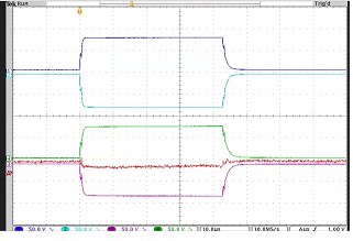
Image3: Correct diff. signal from GGD port
I examined the board in the lab and although a first the issue did not appear; after running the board for a few hours I noted the exact same failure mode with my test setup. The issue seemed to be related to temperature change.
Resolution:
I then investigated possible components that could cause this failure mode. I narrowed down offending part to the opto-coupler PN: HCPL-0710-500. The optical coupler interfaces between the low-voltage logic control signal to the high voltage driver circuit.
By forcing temperature changes on the package of the chip, I can get the failure mode recorded at the experiment...to reproduce in the test setup.
Further investigation revealed that the HCPL-0710-500E as purchased by the vendor were old stock parts and were purchased from a non-reliable source. This part has gone through many revisions a few of which concern the dies packaging and wire bonding. I suspect that this part being pre revision, has inherent issues which the subsequent revisions addressed. There is also the possibility that the part can be counterfeit.
The resolution then is to simply replace the HCPL-0710-500E, with later or the latest revision.
Special Thanks!
A special thanks to Jeff for setting up the TPC as a data logger. This is exactly what was needed in order to capture an intermittent condition like we had here.
- timcam's blog
- Login or register to post comments
