- videbaks's home page
- Posts
- 2024
- 2023
- 2022
- 2021
- 2020
- 2019
- 2018
- December (1)
- November (2)
- October (1)
- September (1)
- August (1)
- July (4)
- April (3)
- March (1)
- February (2)
- January (1)
- 2017
- 2016
- November (1)
- September (2)
- August (2)
- July (1)
- June (1)
- May (1)
- April (1)
- March (1)
- February (1)
- January (1)
- 2015
- 2014
- 2013
- 2012
- 2011
- 2010
- November (3)
- 2009
- My blog
- Post new blog entry
- All blogs
STGC geometry
3/3/2023
Used Jason macro and generated the rad lengtghs distributions vs. phi for the totals package (4 modules).
Code output agrees with the hand calculation from geant thicknesses and radiation length
Slide are in attachment
1/25/2023
Update on radiation length:
I resurrected my method to evaluate the radlength of STGC. The scripts used was the similar to that of FST used earlier.
It does not subdivide materials, but just evaluate the radlengths by tracing material and summing up the integrated radlength
between two planes position an distances before and after a module.
The script can be found in ~videbaks/fst/radlen.C and executed simply. The geometry used is my local one that I handed over to Daniel
with just the bare minimum, not the DEV version that has a material issue.
>root4star
[] .L radlen.C
[] loadGeometry()
[] radlen()
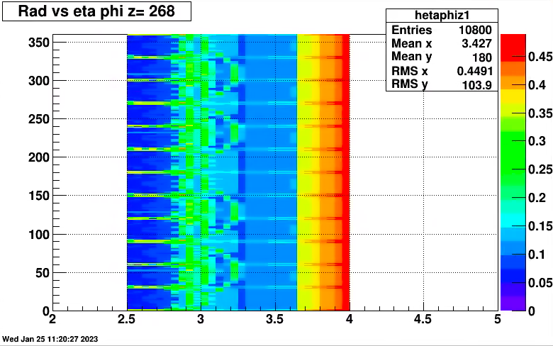
hetaphiz1->Draw() // radlength for eta-phi just before stgc

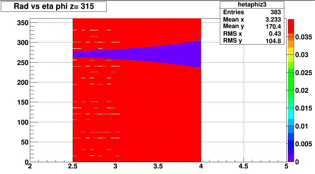
[]plotDiff2D() // plot radlength for just a single chamber. Changes content of hetaphi2,3

Radlen for module 2 phi vs eta. The white stripes is due to binning issues. ~ 3.5%
Its completely uniform apart form hole for beampipe as the geometry is simplified with only PCB, pentane gas and honeycomb.
The STGC geant geometry was explored as there seems to be some issues understanding the radiation length
Nicole, Daniel and I had a discussion on 9/16/2022. I put a few slides together on what I learned.
See attached file.
11/11/22
e-mail to Daniel+
I did spend several hours going through the code. I could see some improvement, but the cross check with starsim revealed several mishaps.
Some of this I traced to possible misunderstanding of coordinate systems in the volume descriptions (for z-directions)
The center of a tubes is at middle of z direction, as is a box. So if you place a box inside a tubes it should be a z=0. In contrast the 0 for a pcon is not at center but has range 0,dz in contrast to a bbox (-dz/2, +dz/2)
Thus the polygon part of the hexgon was displaced compared to the mother volume.
I believe I fixed this for properly for the honeycomb, the gas volumes and the P10.
The honecomb was also placed at zero, and the displaces other volumes moved so the line up without any gaps.
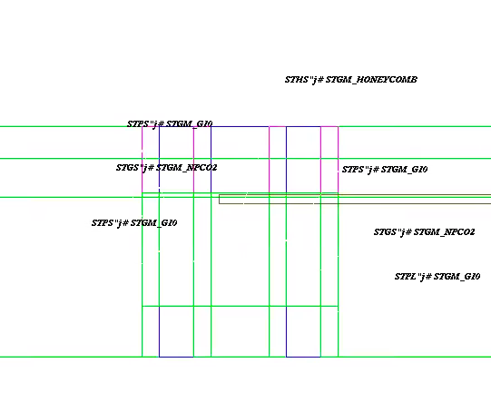
See attached fig (cut view with the g10,gas and honeyvcomb layers.
I have not looked at the brackets etc so the positioning of stmb, stmc stmm and stme will also have to be revisited.

- videbaks's blog
- Login or register to post comments
