IST Sti geometry
Updated IST Sti geometry:
- IST ladder structure and material budget
Figure 1: IST ladder structure
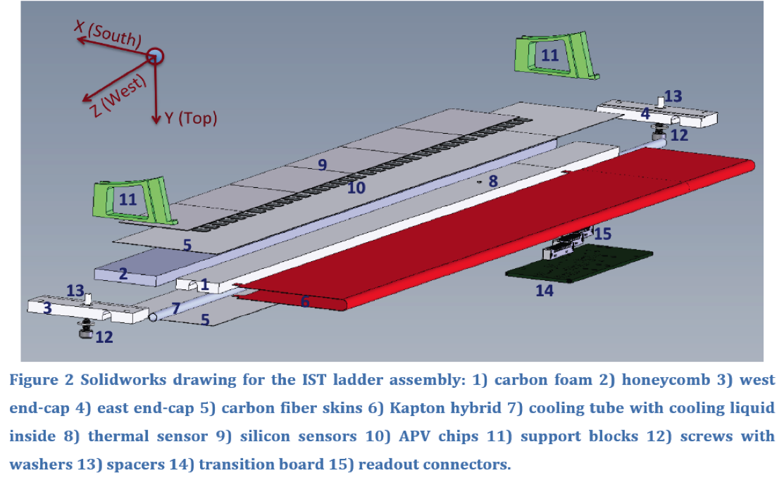
Figure 2: IST material budget
.png)
- Sti geometry update
The Sti does not allow enclosed/overlap volumes in geometry, so there are several re-definitions in Sti for some IST stave components (such as support blocks, carbon foam stave, west/east end-caps). The updated Sti geometry defines the IST in detail with tube/box shapes without overlap or enclosed.
sensitive material: The 6 silicon sensors of a ladder was described by a thin planar shape (300 um of thickness, 3.8016 cm of width along r-phi, 46.34 cm of length along Z direction).
The length of dead edge along Z direction of silicon sensor is 0.08 cm, and gap between two neighboring sensors is 0.04 cm. The silicon pad dimessions are 0.0594 cm (r-phi) and 0.6275 cm (Z).
in-active materials: The IST structure is shown in Fig. 1.
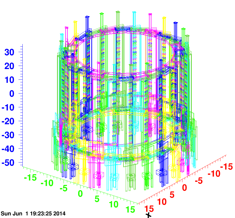
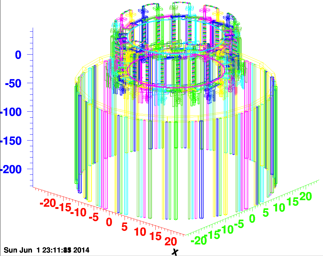
The Sti geometry in middle region has been finished as shown in Fig. 3: -53 cm < Z < 35 cm ( -2.0 < eta < 1.6)
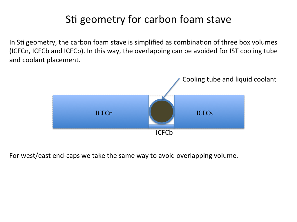
Due to cooling tube passing through carbon foam stave, west end-cap and east end-cap.To avoid the overlaps of them, re-difinitions have been done for these volumes.
(1) The carbon foam stave and end-caps are described by assembly of three simplified boxes to leave an groove for cooling tube/coolant without overlap.
The re-definition is described as below cartoon slide:
(2) The support block is decribed by assembly of box/trapzoid shapes, and simplified tube volume.
Figure 3: IST Sti geometry (middle region)
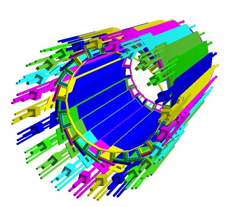
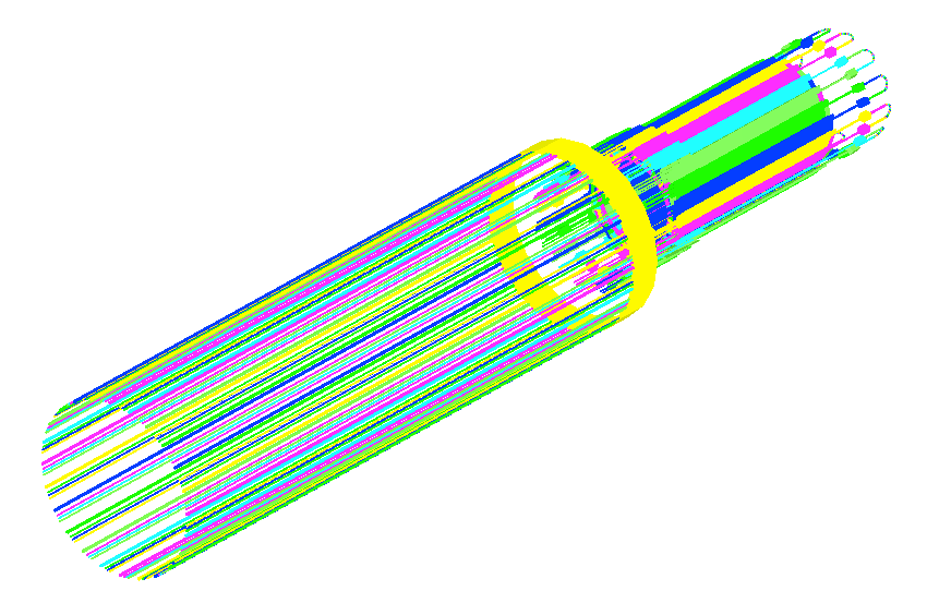
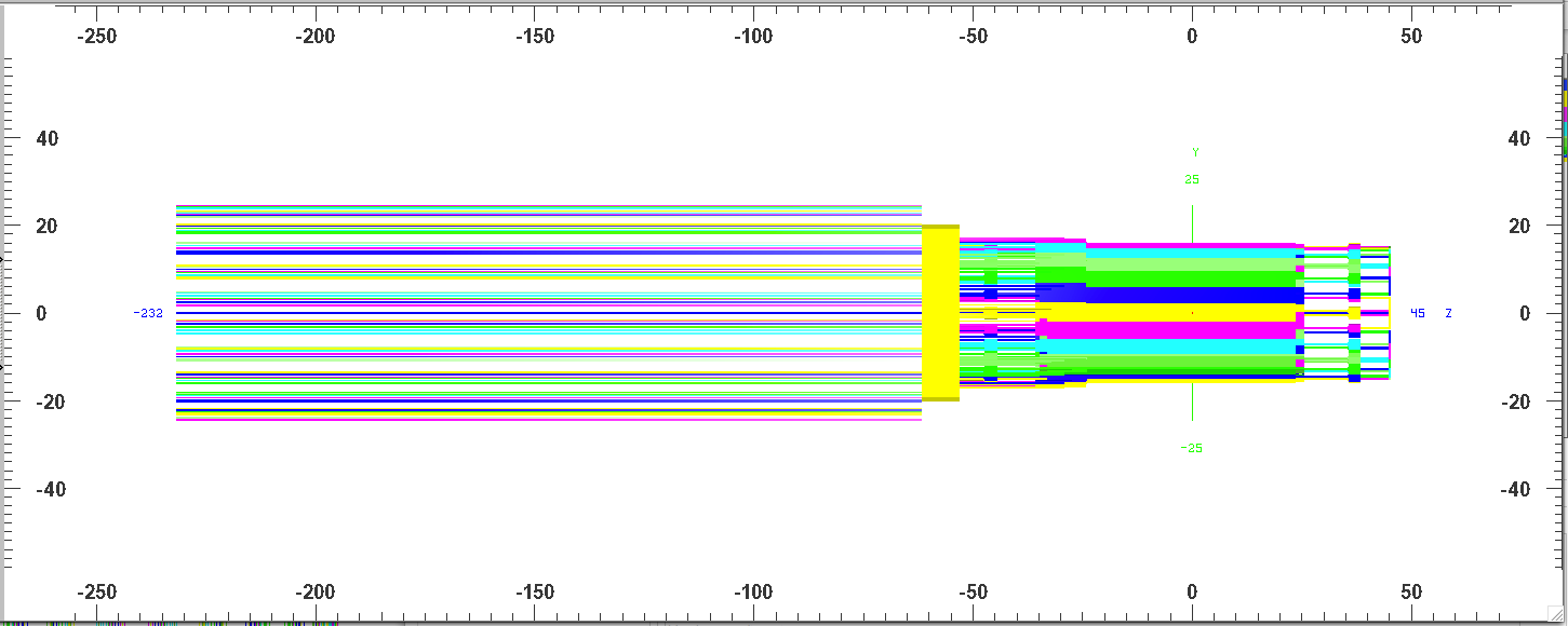
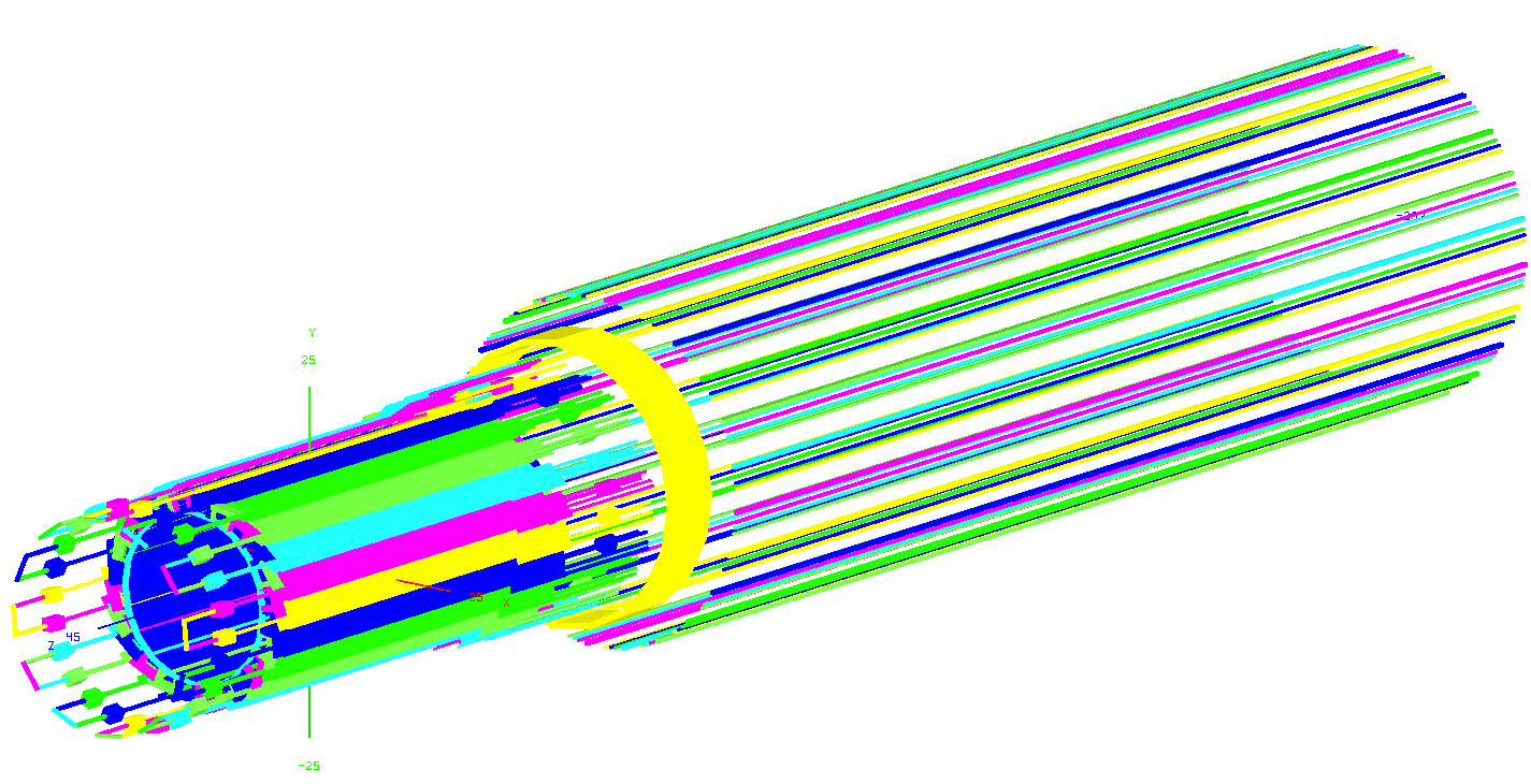
The Sti geomtry with west cooling tube joints/loops (1.6 < eta < 1.9) and east cooling & cabling lines on PIT (-3.0 < eta < -2.0) implemented is shown in Fig. 4.
The cooling/cabling lines in transition area are described with a simple tube volume (The yellow tube between IST middle region and PIT region).
Figure 4: IST Sti geometry (full region)

3) code location
codes: /star/u/ypwang/disk01/stiIstValidation/StRoot/StiIst/StiIstDetectorBuilder.cxx(.h)
//////////////////////////////////////////////////////////////////////////////////////////////////////////////////////
Update on June 3, 2014
(1) The U-sections of west cooling loop are simplified with a box shape with the same volume.
(2) The radius of average tube volume for cooling&cabling at transition area was updated to ~ 20cm.
Fig1. Sti geometry in XOY (left) and YOZ (right) perspective view.
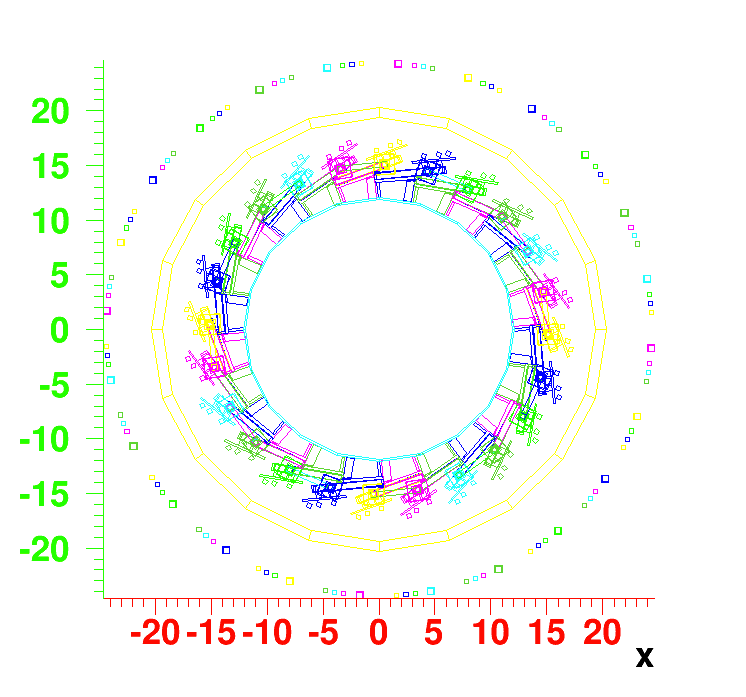
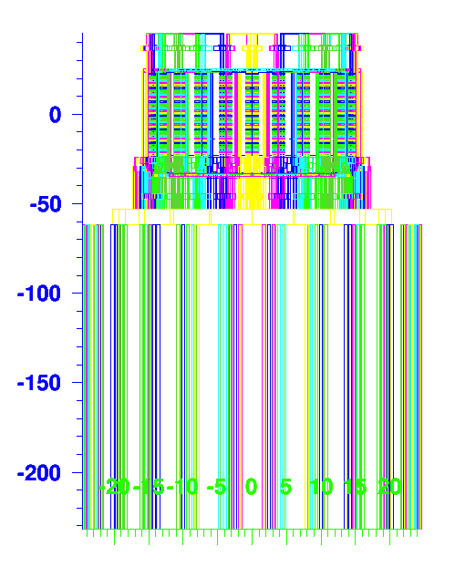
Fig. 2 Sti geometry in YOZ (upper) and XYZ (bottom) orthographic view.
4) To do:
validation by tracking simulation.
- ypwang's blog
- Login or register to post comments
