- yuxip's home page
- Posts
- 2015
- 2014
- December (2)
- November (1)
- October (2)
- September (6)
- August (2)
- July (1)
- June (3)
- May (4)
- April (1)
- March (2)
- 2013
- December (1)
- November (1)
- October (3)
- September (3)
- August (2)
- July (1)
- June (2)
- May (1)
- April (3)
- March (1)
- February (1)
- January (1)
- 2012
- 2011
- My blog
- Post new blog entry
- All blogs
FCS jet Energy/pT resolutions --update
I have re-calibrated ECAL and HCAL in simulation using the "alpha_{0}" intercalibration method. You can find more about intercalibration studies in my last week's update.
alpha_{0} is used to weight the visible energy deposit in HCAL in defining the total calorimeter signal.
E_{rec} = c*(E_{vis}^{ECAL} + alpha_{0}*E_{vis}^{HCAL})
The overall energy scale c is determined by electrons from 10~60 GeV. The final calibrations I used to produce the jet trees are
c = 48.50
alpha_{0} = 0.96*1 .188 = 1 .14
In calculating the jet energy and pt resolutions, a detector jet is matched to the closest particle jet in eta and phi within R_match < 0.5 (R_match = Sqrt[(etaDet-etaPar)^2 + (phiDet-phiPar)^2]). In order to reduce of probability of getting mismatched particle/detector jet pairs I only selected events in which the pT of any non-leading jet is less than 25% of the pT
of the leading jet. The width of ( E_{particle jet} - E_{detector jet} ) / E_{particle jet} is defined as the energy resolution for a certain E_{particle jet} bin.
Figure 1 shows the energy and pT resolution with the above calibrations before any correction to the energy scale is applied.
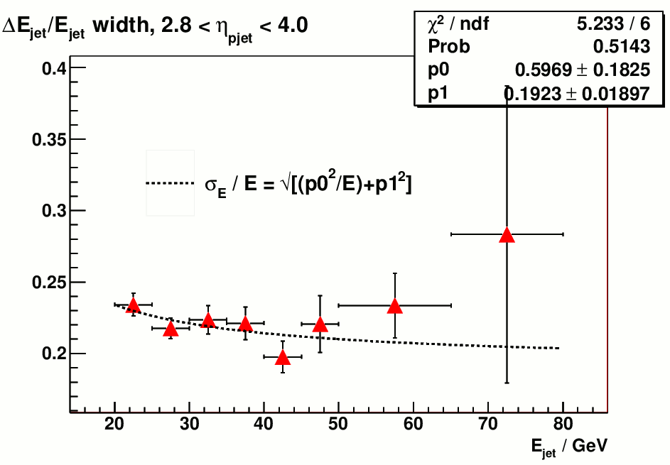
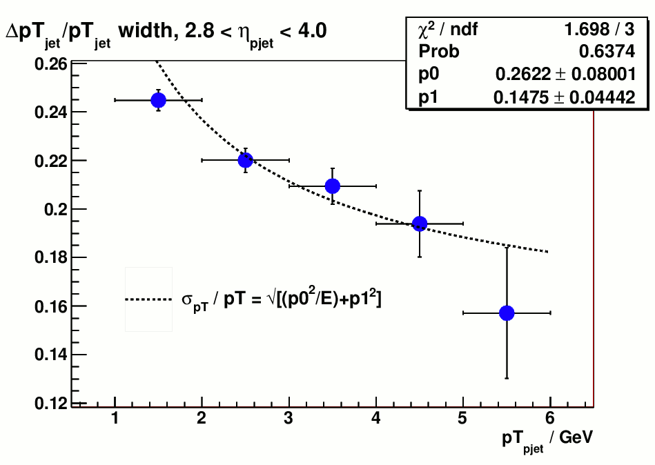
Figure 1 a). jet energy resolution, no correction Figure 1 b) jet pT resolution, no correction
Figure 2). shows the reconstructed jet energy scale compared to the particle jet.
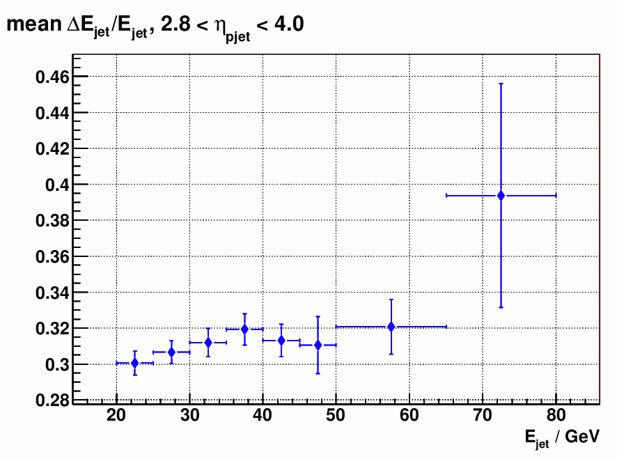
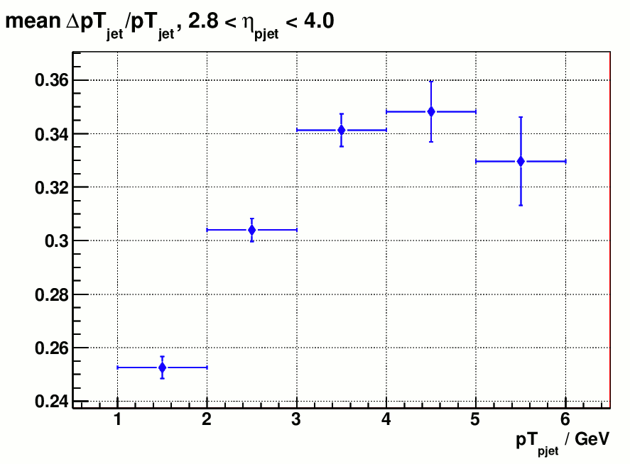
Figure 2 a) distribution of mean ( E_{particle jet} - E_{detector jet} ) / E_{particle jet} Figure 2 b). mean ( pT_{particle jet} - pT_{detector jet} ) / pT_{particle jet}
Figure 2 indicates that the energy scale of reconstructed jet is smaller than particle jet by ~30% before correction, which is expected from the current calibration method. On page 4 of my last week's update it shows the intercalibration factor alpha_{0} becomes energy dependent for single hadrons below 40 GeV and the way I chose alpha_{0} to be
a constant 1.188 underestimates the hadron energy below this limit. But without trying to discriminate between em/hadronic showers this could the best intercalibration we can achieve since it stays as a constant above 40 GeV and it makes the overall energy scale of hadrons (or hadronic showers ) the same as electrons ( or em showers)
Also the fact that the centroid of reconstructed jet energy is far away from the true jet energy makes the resolution a meaningless quantity becase it's not evaluated at the right energy scale. ( Variance(cx) = c^2*Variance(x), when c is 70%, variance of cx is guaranteed to be less than the variance of x ).
So I moved on to try to calculate the correction factors that could bring the reconstructed jet energy to the right scale, in a realistic way. Which means that the correction factors should only depend on reconstructed variables. However, in order to reduce the resolution effect (which produces bin migrations) as much as possible the jet energy corrections were initially calculated in each generated(particle) jet energy and eta bin, then they are projected into the detector jet energy/eta bins to make a weighted average with the correctoins come from other generated bins. Figure 3 shows an example of how the correction was calculated and projected for a certain (E_{gen}, eta_[gen}) bin.
particle/detector jet pairs used in calculating the corrections are selected with:
pT_{non-leading jet} < 0.25*pT_{leading jet}
R_match < 0.2
20 GeV < E_{particle jet} < 80 GeV
2.8 < #eta_{particle jet} < 4.0
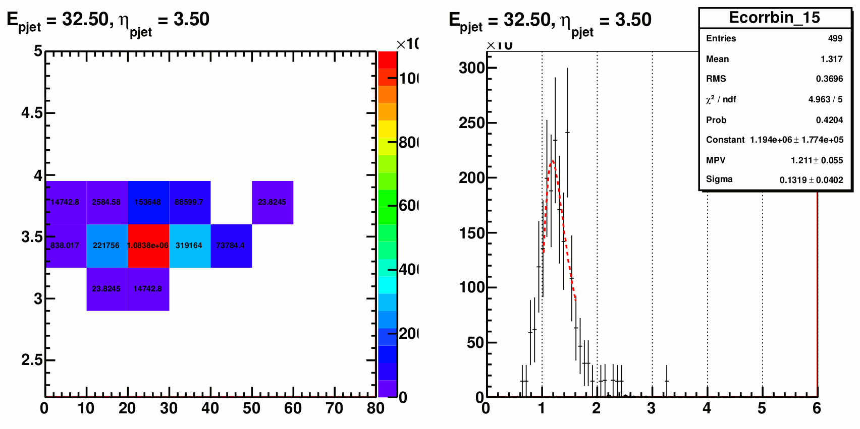
Figure 3. left panel: detector jet eta vs energy for a fixed particle jet eta/energy bin; right panel: distribution of E_{particle jet} / E_{detector jet} for this generated eta/E bin.
The mean of E_{particle jet} / E_{detector jet} dsitribution was used as the correction factor for a specific generated eta/E bin and it assigned to every entry in the corresponding detector eta/E bin. Finally for each detector eta/E bin the corrections that come from different generated eta/E bins were combined and the weighted average was assigned as the jet energy correction for that detector eta/E bin. Simiar correction has also been done for jet pseudorapidity.
Figure 4 shows the final jet energy and pseudorapidity correction matrices.
.gif)
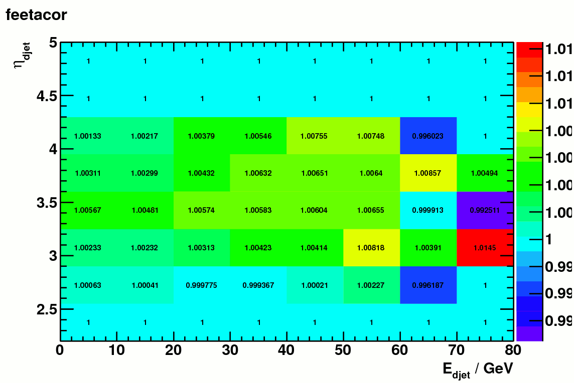
Figure 4 a). jet energy correction matrix ( vs detector jet eta and energy ) Figure 4 b). jet eta correction matrix (vs detector jet eta and energy)
Figure 5 shows the energy and pT resolution after the correction. These include all the particle/detector jet pairs with R _match< 0.5 (the cut on non-leading jet pT is still in place).
.gif)
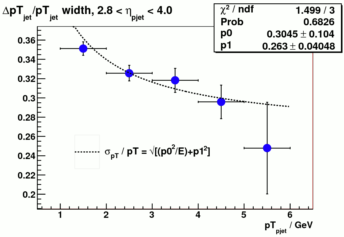
Figure 5 a) jet energy resolution after correction (vs particle jet energy) Figure 5 b) jet pT resolution after correction
Figure 6 shows that the reconstricted energy scale after correction is within 5% of the true energy scale. pT is within 6%. Note that the corrected pT was derived from corrected jet energy and eta.
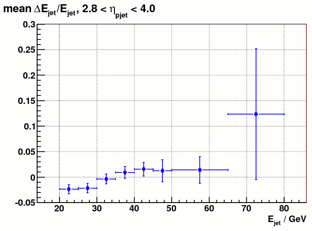
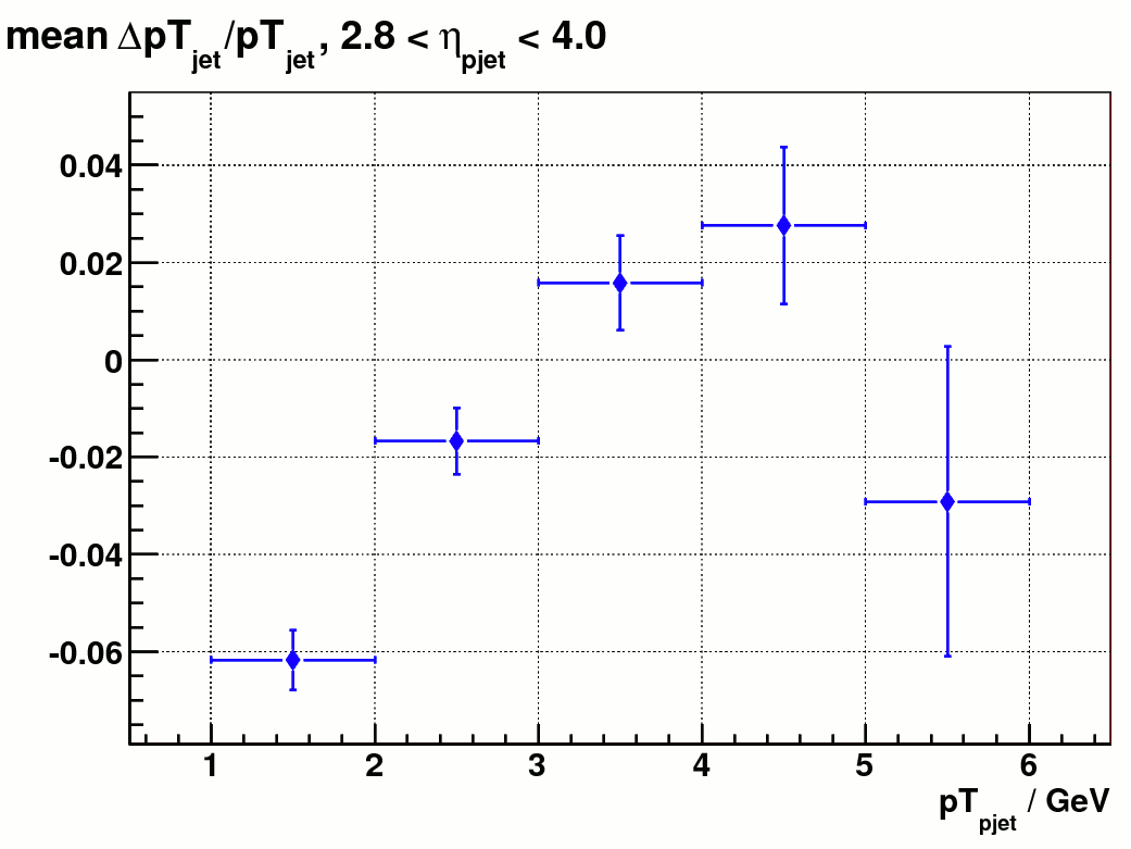
Fig. 6 a) distribution of mean ( E_{particle jet} - E_{detector jet} ) / E_{particle jet} after correction Fig 6 b). mean ( pT_{particle jet} - pT_{detector jet} ) / pT_{particle jet} after correction
Finally Figure 7 shows the fit to delta_E / E_{pjet} from which the resolution was computed. For a few bins at higher energy the distribution is not so much of a Gaussian. As a comparison the RMS was also calculated as an alternative quantity to represent resolution, which is showed in figure 8. The errors of RMS was still from the Gaussian fit.
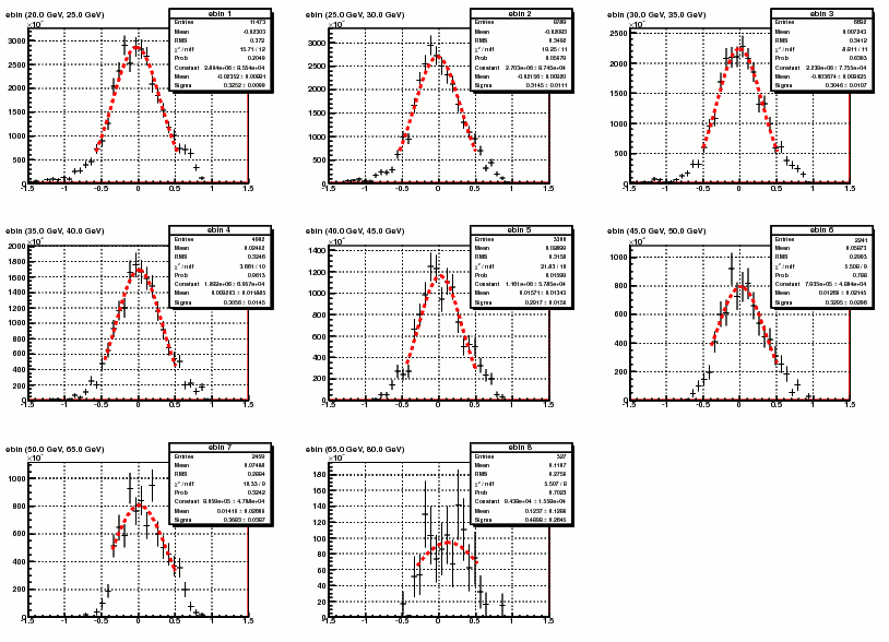
Figure 7. Fit to the delta_E / E_{pjet} distribution
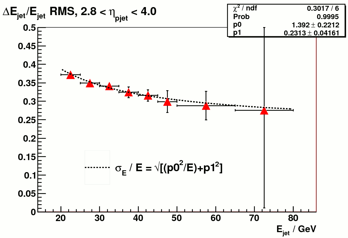
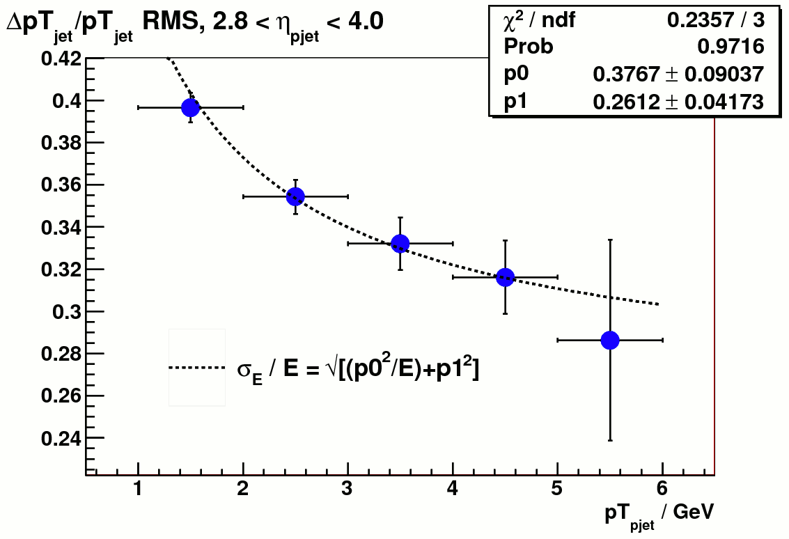
Figure 8. a) rms of delta_E / E_{pjet} vs particle jet energy Figure 8. b) rms of delta_pT / pT_{pjet} vs particle jet pT
Groups:
- yuxip's blog
- Login or register to post comments