- dilks's home page
- Posts
- 2019
- 2018
- December (1)
- November (1)
- October (1)
- August (2)
- July (4)
- June (3)
- May (1)
- April (2)
- March (2)
- February (1)
- January (5)
- 2017
- December (3)
- November (1)
- October (2)
- September (3)
- August (2)
- July (2)
- June (1)
- May (2)
- March (3)
- February (3)
- January (3)
- 2016
- November (2)
- September (4)
- August (2)
- July (6)
- June (2)
- May (3)
- April (1)
- March (2)
- February (3)
- January (2)
- 2015
- December (3)
- October (3)
- September (2)
- August (6)
- June (3)
- May (3)
- April (4)
- March (3)
- February (5)
- January (3)
- 2014
- December (1)
- November (1)
- October (3)
- September (4)
- August (3)
- July (3)
- June (2)
- May (2)
- April (2)
- March (1)
- 2013
- 2012
- 2011
- My blog
- Post new blog entry
- All blogs
FMS+uvLED GUI for Shift Crew Operation -- (Front-end functionality)
This is a presentation on the new Shift Crew FMS+uvLED Control GUI for run 17. It includes a software interlock between the FMS HV and uvLED power.
Click on any image to enlarge it.
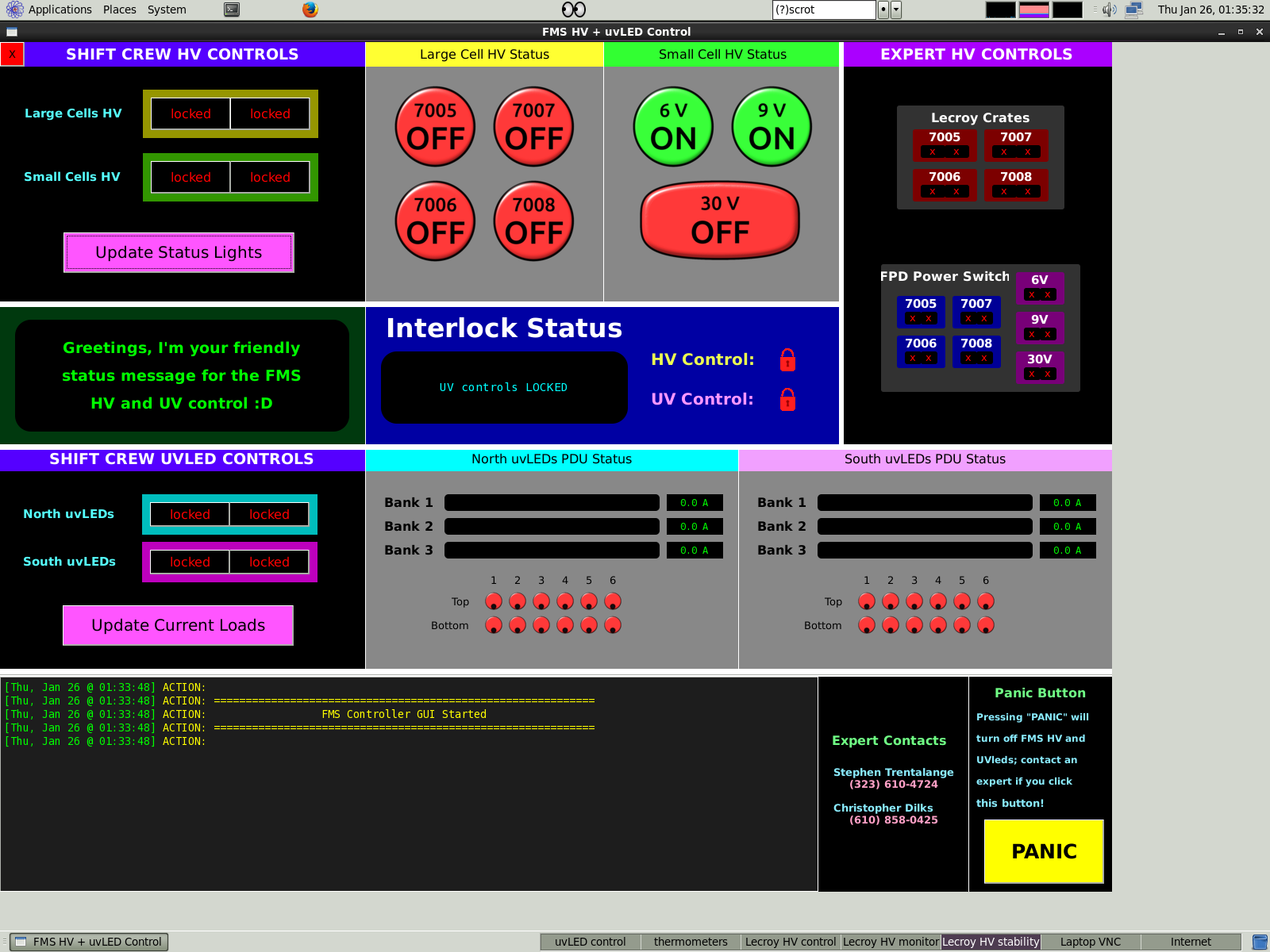
When the GUI is first opened, all on/off controls are locked. Update buttons are never locked. The image below shows the GUI in this state.
-- upper left is shift crew controls for the HV
-- upper middle is HV status indicators
-- upper right is HV "expert controls" for controlling individual Lecroy crates and small cell voltage levels
-- below the shift crew HV control panel is a status window, which updates as the operator is using the GUI
-- to the right of the status window is the interlock status window, which tells the operator the state of the interlock
-- below the status windows are the UV controls on the left and the statuses for north and south in the middle and right
-- at the bottom is a log output window; different levels of messages have different colors and the output will also be sent to a webpage, which we can
check at any time
-- to the right of that are expert contacts info
-- bottom right is a PANIC button, which turns off both UV and HV and tells the operator to contact an expert
.
.
.
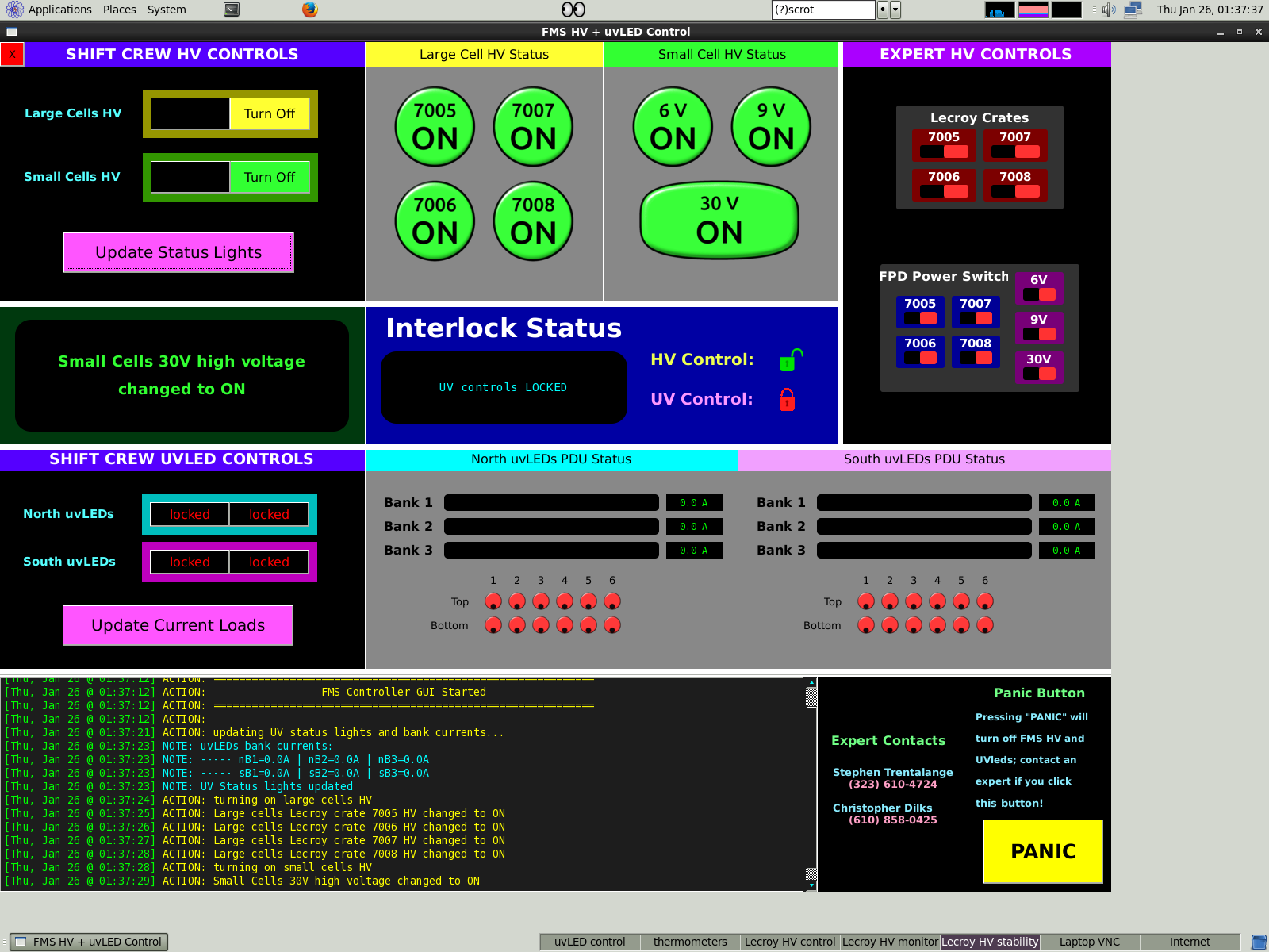
This is when the HV is on. Note that UV controls are locked, but HV controls remain unlocked.
.
.
.
This shows an error which occurs when the operator tries to turn OFF the 9V while the 30V is on (see expert control panel and mouse cursor)
The action is prevented and an error is printed to the log file in red

.
.
.
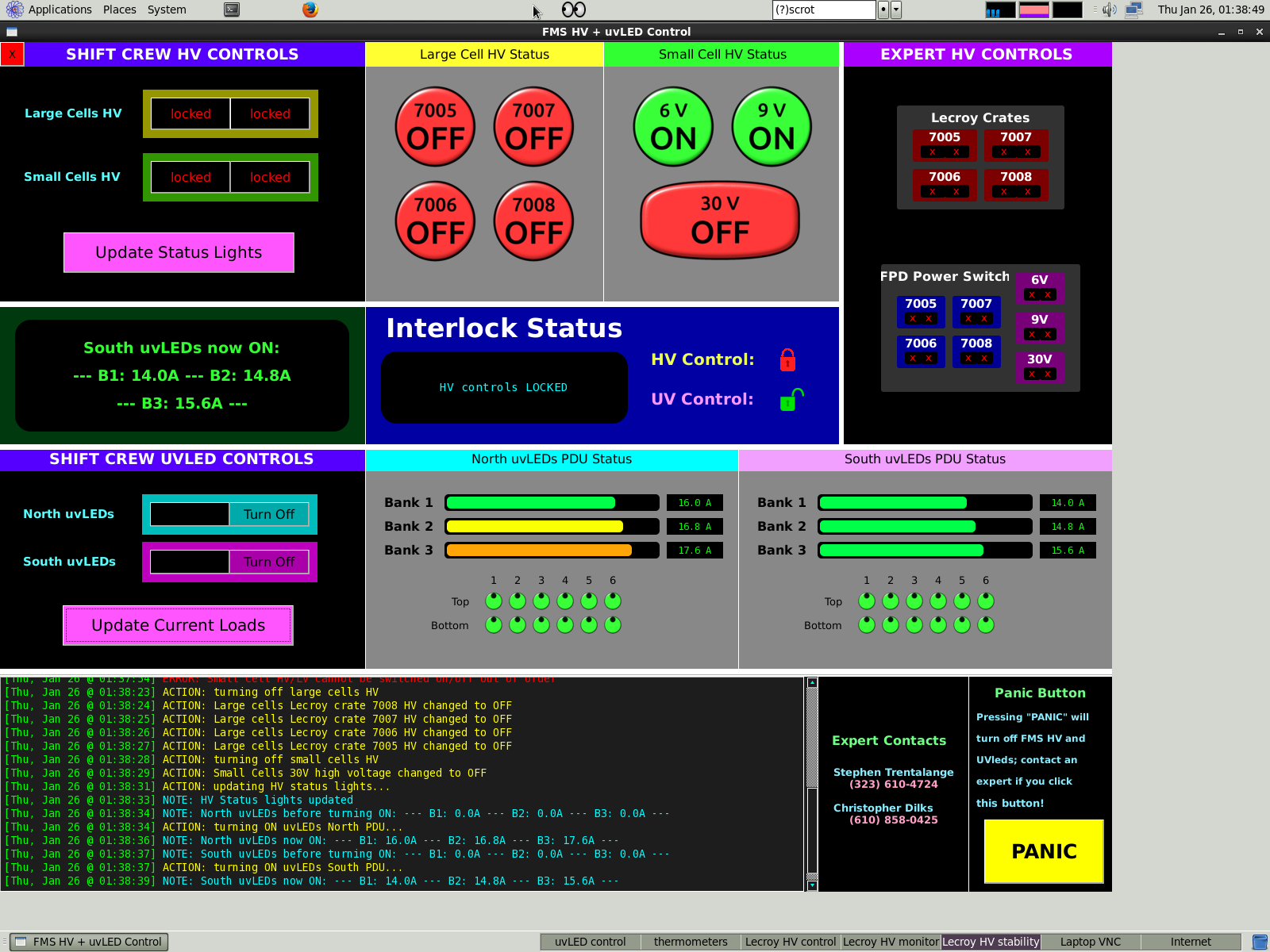
This shows the UVleds on with normal (faked) current loads. The HV is off.
Bank currents are printed to the log file so we can keep track of the health of the UVled array
.
.
.
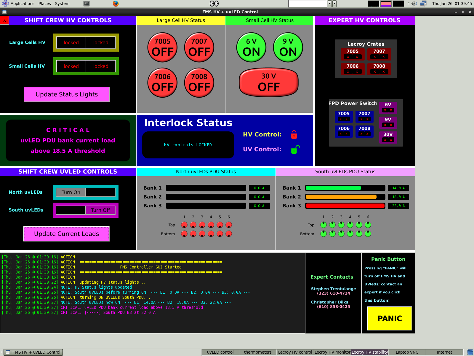
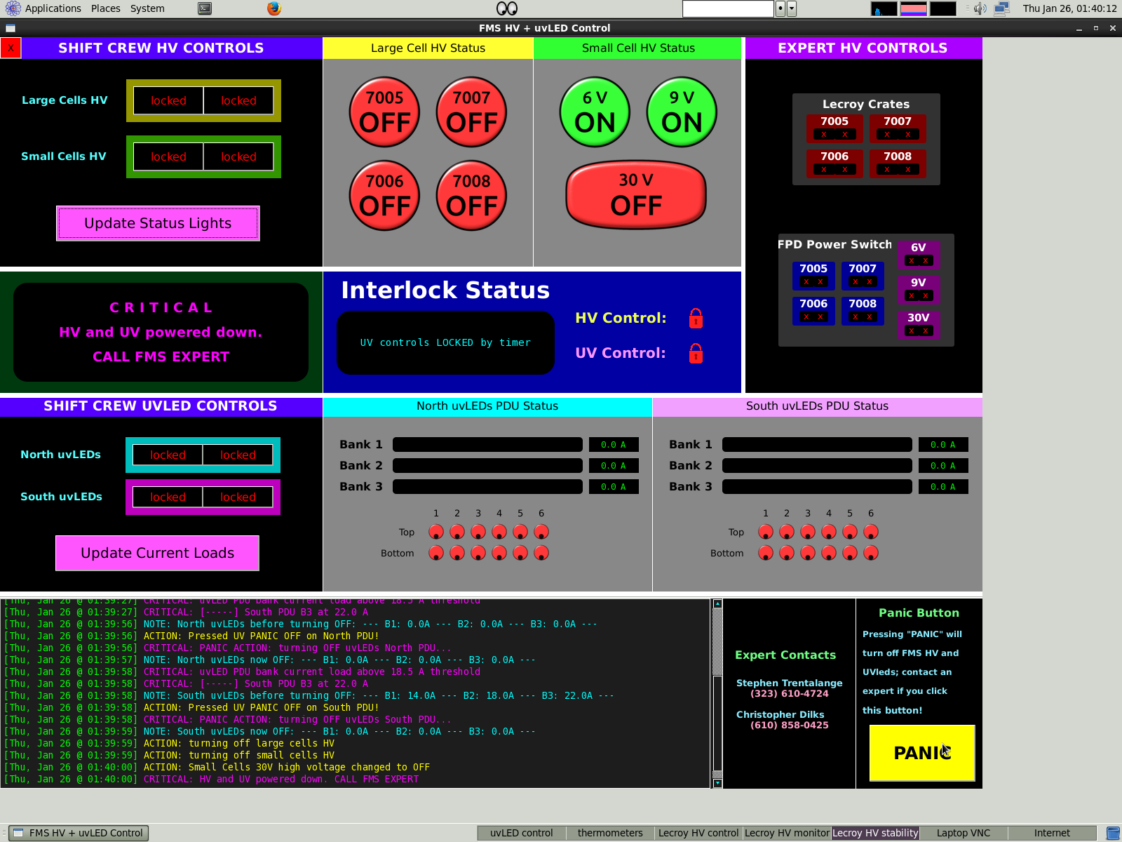
This shows a critical error which occurs after trying to turn on the south uvLEDs, where the current load of bank 3 is far too high.
A critical error is reported in magenta to the log file.
Eventually, we may configure it to send us a text message whenever a critical error occurs.
Shift crew instructions will instruct the operator to press the PANIC button in this scenario
.
.
.
And this is the state after the PANIC button was pressed
.
.
.
.
VIDEO DEMO OF SHIFT CREW OPERATION ---------------------------------------------------------------------------------------------------------------------------------------
The following video demonstration (AVI format, 12 MB download, ~1.5 min long) is a SIMULATION of the GUI and software interlock behavior.
-1- It starts with the FMS HV powered on
-2- the HV is powered down
-3- HV update button is clicked to double check HV voltages are zero, which subsequently releases the lock on the UV controls
-- note that there is a timeout (currently 1 minute) during which the controls are unlocked; after the time expires, the controls are locked again.
This is a safety feature which helps guarantee that only the most recent data which indicate the state of the HV (or UV) is used when determinining
the operator's ability to turn on the UV (or HV) system
-4- UVleds are then turned on (with fake current loads!) (note, a critical error is reported for south bank 3, where the current is abnormally high)
-5- After a bit, the UVleds are turned off and the update UV bank currents is clicked to verify they are off, which subsequently releases HV control lock
-6- The HV is powered back on, and the FMS is ready to take data
Video Demonstration: http://www.star.bnl.gov/protected/spin/dilks/linked_from_drupal/gui_demonstration.avi
.
.
.
TASKS ---------------------------------------------------------------------------------------------------------------------------------------
-- have someone test the front-end GUI and interlock behavior to try to "break" the FMS (obviously done while in 'GUI simulation mode')
-- back-end control and readback scripts; started Lecroy readback scripts, which currently appear to be working
-- connect front-end GUI to back-end scripts
-- slowly enable the full capability of the scripts so that tests can be run incrementally and any possible failure modes are reported back (without actually causing any real problems with the FMS, of course)
-- run some test HV --> UV --> HV real operations from the GUI while fully monitoring the back-end and manually checking the detector states
-- designate a webserver where the log file can be easily viewed remotely
-- configure CRITICAL log messages to be sent to experts via text message
Groups:
- dilks's blog
- Login or register to post comments