Impact of TPC Supersector Mis-alignment on HFT Tracking
There was some suspect that even there is a TPC mis-alignment, when tracking outside-in, the residual resolution is mostly dominated by the projection error, so the impact on the HFT tracking efficiency might be minimal (e.g. the global TPC track pointing resolution is about 2mm while the shift so far observed is about 0.7mm). To estimate the impact of the TPC mis-alignment on HFT tracking, I did a toy MC calculation using the simple helix track fitting and the findings are summarized below.
Only detector hit resolutions are considered here, and only focusing on the transverse plane (XY plane). The detector position and hit resolution parameters are listed below:
PXL1 r = 2.8 cm, sigma = 12 micron
PXL2 r = 8.0 cm, sigma = 12 micron
IST r = 14 cm, sigma = 170 micron
TPC all parameters used are ideal positions
Two kinds of mis-alignment are considered
- global rotation w.r.t to the supersector center with a rotation angle of 0.6 mrad
- global offset in r-phi direction with a shift of 0.7 mm
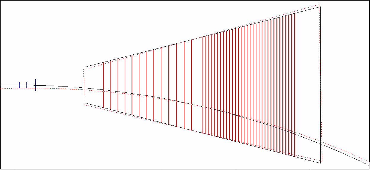
Both will give about 0.7 mm offset in the DCA to the primary vertex when recontructing the track with TPC hits only. The global roation w.r.t to the supersector center was considered here particularly in view of the case that the TPC alignment calibration may be coupled with a mis-calibrated space charge correction while the later will introduce the TPC hits rotated globally w.r.t to the super sector center and to the same direction for all TPC sectors (see the following cartoon for this case).
All HFT hits are considered to have no mis-alignment in this study. Thus only hit resolution will be used to smear the hit position.
I used a simple circle fit to all reconstructed hits. The following tracking configurations are calculated separately
- TPC hits only
- TPC + IST hits
- TPC + IST + PXL2 hits
- TPC + IST + PXL2 + PXL1 hits
I then calculated the track parameters, then the track momentum and also the residuals w.r.t the primary vertex as well as on each HFT layer.
In all following figures, I will show the fit mean (closed symbols) and sigma (open symbols) distributions for all three alignment setup
- Ideal - black
- Gamma - global rotation w.r.t the TPC center - 0.6mrad - red
- Shift - global shift along r-phi direction - 0.7mm - green
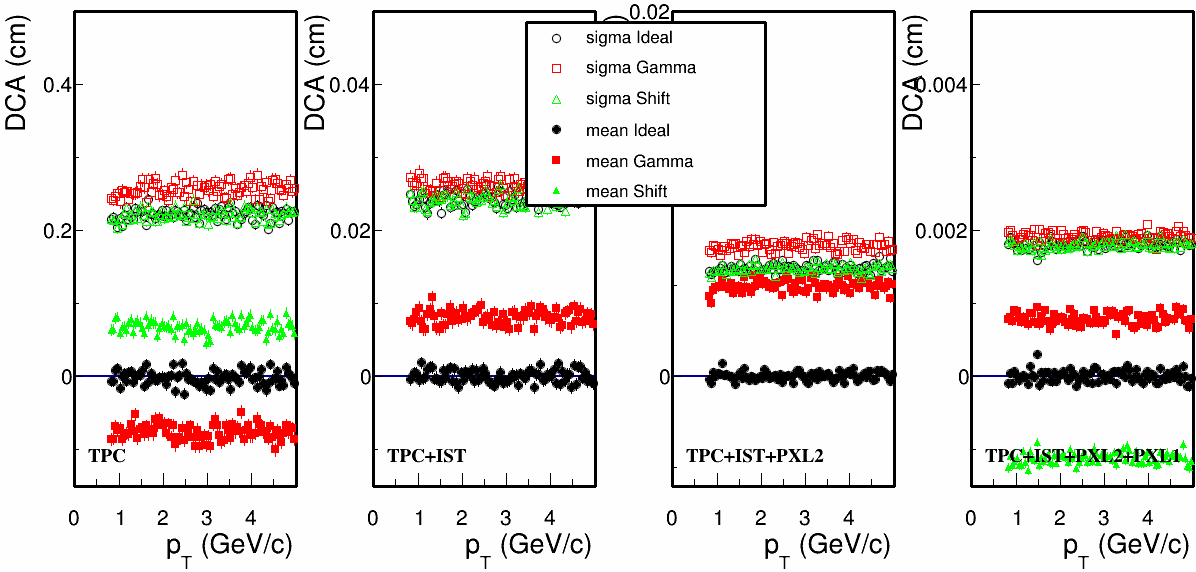
Fig. 1, DCA to the primary vertex for different tracking configurations. Note, scales on each panel are different.
First panel, one see both mis-aligned cases give a DCA shift (red and green closed symbols) by about 0.7mm. When including HFT hits in tracking, the offsets are still there. In the last panel when having all three layer of HFT hits included, one can see the shift in DCA is about 10 (8-12) microns in both cases.
.png)
Fig.2, pT resolution (in 1/pT difference) of global tracks with different tracking configurations for three different alignment setup.
The left one with TPC tracking only show a resolution about 2% which should be close to what we expect in the real tracking. With inclusion of each HFT layer, the momentum resolution is increased. One can see that for both mis-aligned cases, the mean shift in the pT resolution is close to one sigma of the pT resolution for all different tracking configurations.

Fig. 3, Residual on each HFT layer when including hits from all outer layers + TPC.
This figure compares the residual mean shift w.r.t the resolution expected from outside. It should reflect the outside-in tracking procedure. One can see eventually onto PXL1 layer (right most panel), the shifts (red and gree) of the track projection residual from both mis-aligned cases are on the order of 1 sigma or more. The shifts seem to be sizable as the tracking will then define the search window based on these resolutions.
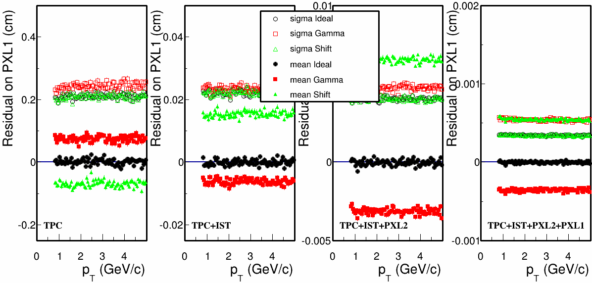
Fig. 4, PXL1 residual for all four different tracking configurations.
Looking more systematically, even with PXL1 included in tracking (right most panel), the shifts in PXL1 layer are also about the level of the resolution (although both are about 5 microns now).
Conclusion:
- A TPC mis-alignment at the level of 0.7mm (either due to the global rotation or shift) can have a sizable impact on the HFT tracking. The shifts observed are comparable to the expected resolution in the track residuals.
- To minimize the impact on the HFT tracking, I think one should probably require the shift to be < 1/2 or 1/3 of the resolution. This sets the mis-alignment tolerance for HFT tracking at the level of 200-300 microns.
P.S. In this simulation, only the hit resolutions are considered. For low pT tracks, the multiple columb scattering will also contribute to the projection error, so the impact can be smaller.
- dongx's blog
- Login or register to post comments