Distortion effects on padrow shape
Applying the following distortions:
StMagUtilities::CommonSta  Using mode option 0xBA70
StMagUtilities::ReadField  Reading  Magnetic Field  Measured Full Field,  Scale factor = 1.000000
StMagUtilities::ReadField  Filename is bfield_full_positive_2D.dat, Adjusted Scale factor = 1.000000
StMagUtilities::ReadField  Version  2D Mag Field Distortions + Padrow 13 + Twist + Clock + IFCShift
+ SpaceChargeR2 + ShortedRing + 3DGridLeak
StMagUtilities::ReadField  Reading  2D Magnetic Field file: bfield_full_positive_2D.dat
StMagUtilities::ReadField  Reading  3D Magnetic Field file: bfield_full_positive_3D.dat
StMagUtilities::ReadField  Reading  CM Electric Field Distortion File: membrane_efield.dat
StMagUtilities::ReadField  Reading  Endcap Electric Field Distortion File: endcap_efield.dat
StMagUtilities::BField        =  4.9798 kGauss at (0,0,0)
StMagUtilities::DriftVel      =  5.54 cm/microsec
StMagUtilities::TPC_Z0        =  208.7 cm
StMagUtilities::TensorV1+V2   =  1.35 1.1
StMagUtilities::OmegaTau1+2   =  -2.79246 -2.27534
StMagUtilities::XTWIST        =  -0.165 mrad
StMagUtilities::YTWIST        =  0.219 mrad
StMagUtilities::SpaceCharge   =  0 Coulombs/epsilon-nought
StMagUtilities::SpaceChargeR2 =  0 Coulombs/epsilon-nought  EWRatio = 1
StMagUtilities::IFCShift      =  0.008 cm
StMagUtilities::CathodeV      =  -27950 volts
StMagUtilities::GG            =  -115 volts
StMagUtilities::EastClock     =  0 mrad
StMagUtilities::WestClock     =  -0.43 mrad
StMagUtilities::Side          =  Location of Short E=0 / W=1
StMagUtilities::Cage          =  Location of Short IFC = 0 / OFC = 1
StMagUtilities::Ring          =  Rings - Location of Short counting from the CM
StMagUtilities::MissingOhms   =  MOhms Missing Resistance
StMagUtilities::CompResistor  =  MOhm Compensating Resistor Value
StMagUtilities::InnerGridLeak =  0 53 0
StMagUtilities::MiddlGridLeak =  15 121.8 3
StMagUtilities::OuterGridLeak =  0 195 0
(SpaceCharge is manually set to 0.01, but doesn't appear in the above output.)
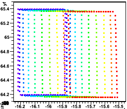
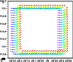
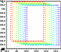
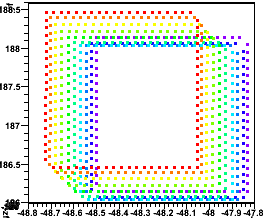
I find the following altered padrow shapes for padrows 2, 12, 15, and 44. The colors represent z (purple is at z=200 cm, nearly no drift, and very little distortion, while red is at z=20 cm, nearly the full drift and most distorted). I have plotted points along the upper and lower padrow borders, as well as vertically along the left and right borders of a few pads across the padrow:
padrow 2:

padrow 12:
padrow 15:

padrow 44:

__________________
Next I plot the borders around pad 0 for each of these padrows, with the same z colors (left -> right, padrows 2,12,15,44):


Generally speaking, the distortions do little to change each pad from being describable as a parallelogram, and generally still as a rectangle.
-Gene
- genevb's blog
- Login or register to post comments
