- genevb's home page
- Posts
- 2025
- 2024
- 2023
- 2022
- September (1)
- 2021
- 2020
- 2019
- December (1)
- October (4)
- September (2)
- August (6)
- July (1)
- June (2)
- May (4)
- April (2)
- March (3)
- February (3)
- 2018
- 2017
- December (1)
- October (3)
- September (1)
- August (1)
- July (2)
- June (2)
- April (2)
- March (2)
- February (1)
- 2016
- November (2)
- September (1)
- August (2)
- July (1)
- June (2)
- May (2)
- April (1)
- March (5)
- February (2)
- January (1)
- 2015
- December (1)
- October (1)
- September (2)
- June (1)
- May (2)
- April (2)
- March (3)
- February (1)
- January (3)
- 2014
- December (2)
- October (2)
- September (2)
- August (3)
- July (2)
- June (2)
- May (2)
- April (9)
- March (2)
- February (2)
- January (1)
- 2013
- December (5)
- October (3)
- September (3)
- August (1)
- July (1)
- May (4)
- April (4)
- March (7)
- February (1)
- January (2)
- 2012
- December (2)
- November (6)
- October (2)
- September (3)
- August (7)
- July (2)
- June (1)
- May (3)
- April (1)
- March (2)
- February (1)
- 2011
- November (1)
- October (1)
- September (4)
- August (2)
- July (4)
- June (3)
- May (4)
- April (9)
- March (5)
- February (6)
- January (3)
- 2010
- December (3)
- November (6)
- October (3)
- September (1)
- August (5)
- July (1)
- June (4)
- May (1)
- April (2)
- March (2)
- February (4)
- January (2)
- 2009
- November (1)
- October (2)
- September (6)
- August (4)
- July (4)
- June (3)
- May (5)
- April (5)
- March (3)
- February (1)
- 2008
- 2005
- October (1)
- My blog
- Post new blog entry
- All blogs
Effect of OFCW short location for rings 181-182
The location of the short on the OFCW is known to be between rings 181 and 182. The midpoint between those two rings is at z = 208.8 cm, as discernable in this schematic. Because we usually perform the distortion calculations within a box whose boundary is defined by the gating grid, and the gating grid is located at z = 208.707 cm, the ideal location to account for the short is just outside that box.
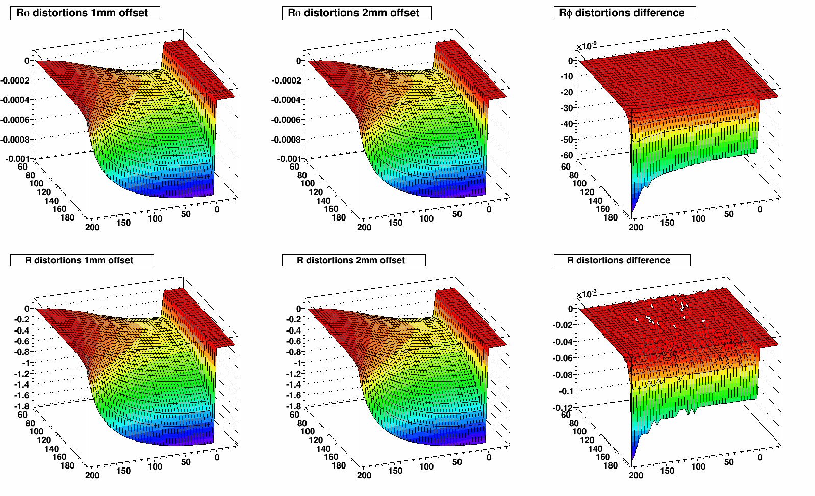
To deal with this, we perform the distortion calculation at a non-ideal location, offset by 1 mm to place it just inside the edge of the box. This offset position will have a small impact on the calculated distortions. To get an idea of the significance of the impact, I have plotted here the effects of shifting by an additional 1 mm (for a total offset of 2 mm from ideal). Shown are azimuthal (Rφ, top) and radial (R, bottom) distortion maps (for FullField) as a function of radius and z for the used 1 mm offset (left), and additional offset to 2 mm (middle) and their difference (right). All units on the plots are [cm].
The maximum Rφ and R distortion differences are on the order of 10-7 cm and 10-4 cm (1 micron) respectively. The conclusion is that this offset location effect is negligible.
-Gene
- genevb's blog
- Login or register to post comments

