EPD Timing Scan Dec 2021
Updated on Mon, 2021-12-13 17:42. Originally created by lisa on 2021-12-13 15:43.
The timing scan procedure was developed a few years ago. It is described in detail at https://drupal.star.bnl.gov/STAR/blog/lisa/epd-timing-scan-run-2018.
This year's EPD timing Labels (used at Run Control) are:
(Note the rules: TAC_Stop = 2*QTC_Start + 18; End=Start+16)
Optional reading:
Some details. (Fuller story in the 2018 post.)
The first goal is to find the gate delay (label START_DELAY in Run Control) that maximizes the charge integration in the STAR QT units. The STAR ADCs (called "QTs") are in 3 "EQ" crates. There are two "flavors" of QT, QT32B and QT32C. They can/will have different optimum timing settings. Also, because the forward upgrade detector on the West side requires extra cable and a splitting unit, the optimum settings for STAR_DELAY will be different for East and West.
The "optimum" setting is determined for each of 744 tiles. (Finite statistics or small variations will make different tiles differ slightly.) Below are one histogram for each QT, of the optimum values reported for each of the 32 channels in a QT32B or 16 channels in a QT32C. East/West and B/C are distinguished by colors; see the legend.
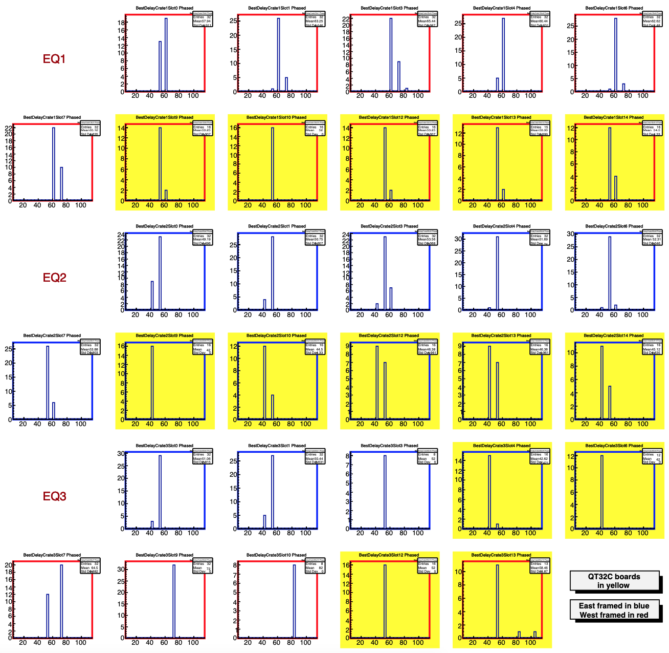
Figure 1. - this is page 875 of the huge pdf file
Based on the above (ignoring EQ3 Crates 7,9,10 because the fits went bad there for some reason - see e.g. pages 713 and 872 of the huge pdf file with all the details):
Having now found the "compromise" delay value, we reduce the delay a little bit more, for the QT32Cs. This is to help insure that the leading-edge discriminators will fire-- they are only active once the gate opens. These discriminators are used in the TACs in the QT32Cs, which in turn can be used in the STAR trigger. In 2018, Akio suggested reducing these delays by 20 ns. As seen in the figures below, this will reduce the integrated charge by ~20%.
Unlike in 2018, I will not reduce the delay on the QT32Bs, as we do not use the timing on those modules. No point throwing away signal (and resolution).
.png)
Figure 2. - this is page 831 of the huge pdf file. It shows the integrated charge as a function of gate delay for a QT32C on the East side. While the maximum amount of charge corresponds to a delay of 45, we will reduce the delay to 25. The chart shows that the reduction in integrated charge is not too bad.
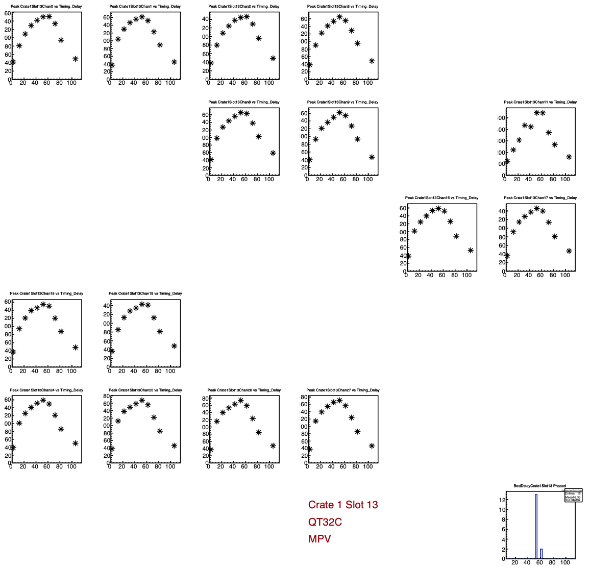
Figure 3. - this is page 852 of the huge pdf file. It shows the integrated charge as a function of gate delay for a QT32C on the West side. While the maximum amount of charge corresponds to a delay of 55, we will reduce the delay to 35. The chart shows that the reduction in integrated charge is not too bad.
dd
Because there is an obsolete version of the code that is floating around (using the wrong "mapping" labels), I am posting the macro here and at the bottom.
This year's EPD timing Labels (used at Run Control) are:
| Label | Value |
|---|---|
| EPD_QTb_E_Gate_Start_Delay | 55 |
| EPD_QTb_E_Gate_End_Delay | 71 |
| EPD_QTc_E_Gate_Start_Delay | 25 |
| EPD_QTc_E_Gate_End_Delay | 41 |
| EPD_QTc_E_TAC_Stop | 68 |
| EPD_QTb_W_Gate_Start_Delay | 65 |
| EPD_QTb_W_Gate_End_Delay | 81 |
| EPD_QTc_W_Gate_Start_Delay | 35 |
| EPD_QTc_W_Gate_End_Delay | 51 |
| EPD_QTc_W_TAC_Stop | 88 |
(Note the rules: TAC_Stop = 2*QTC_Start + 18; End=Start+16)
Optional reading:
Some details. (Fuller story in the 2018 post.)
The first goal is to find the gate delay (label START_DELAY in Run Control) that maximizes the charge integration in the STAR QT units. The STAR ADCs (called "QTs") are in 3 "EQ" crates. There are two "flavors" of QT, QT32B and QT32C. They can/will have different optimum timing settings. Also, because the forward upgrade detector on the West side requires extra cable and a splitting unit, the optimum settings for STAR_DELAY will be different for East and West.
The "optimum" setting is determined for each of 744 tiles. (Finite statistics or small variations will make different tiles differ slightly.) Below are one histogram for each QT, of the optimum values reported for each of the 32 channels in a QT32B or 16 channels in a QT32C. East/West and B/C are distinguished by colors; see the legend.
Figure 1. - this is page 875 of the huge pdf file
Based on the above (ignoring EQ3 Crates 7,9,10 because the fits went bad there for some reason - see e.g. pages 713 and 872 of the huge pdf file with all the details):
- West-side EQ32Bs want START_DELAY ~65
- East-side EQ32Bs want START_DELAY ~55
- West-side EQ32Cs want ~55 (below, we reduce this to 35)
- East-side EQ32Cs want ~45 (below, we reduce this to 25)
Having now found the "compromise" delay value, we reduce the delay a little bit more, for the QT32Cs. This is to help insure that the leading-edge discriminators will fire-- they are only active once the gate opens. These discriminators are used in the TACs in the QT32Cs, which in turn can be used in the STAR trigger. In 2018, Akio suggested reducing these delays by 20 ns. As seen in the figures below, this will reduce the integrated charge by ~20%.
Unlike in 2018, I will not reduce the delay on the QT32Bs, as we do not use the timing on those modules. No point throwing away signal (and resolution).
Figure 2. - this is page 831 of the huge pdf file. It shows the integrated charge as a function of gate delay for a QT32C on the East side. While the maximum amount of charge corresponds to a delay of 45, we will reduce the delay to 25. The chart shows that the reduction in integrated charge is not too bad.
Figure 3. - this is page 852 of the huge pdf file. It shows the integrated charge as a function of gate delay for a QT32C on the West side. While the maximum amount of charge corresponds to a delay of 55, we will reduce the delay to 35. The chart shows that the reduction in integrated charge is not too bad.
dd
Because there is an obsolete version of the code that is floating around (using the wrong "mapping" labels), I am posting the macro here and at the bottom.
»
- lisa's blog
- Login or register to post comments