First EPD bias scan for Run 24
Updated on Sat, 2023-05-27 19:57. Originally created by lisa on 2023-05-27 18:49.
Some notes:
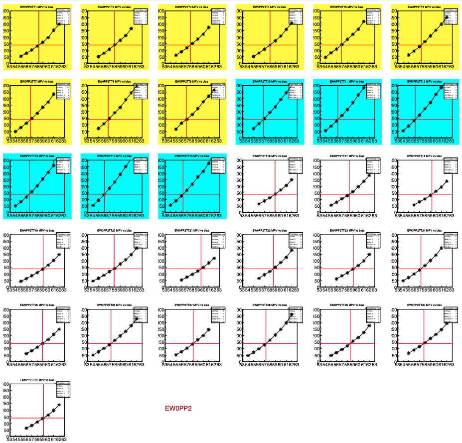
Above is shown the gain curves for all tiles (1-31) in East PP02. Each pad shows position of MIP peak in ADC, versus bias (VSET) value, for one tile. White/Yellow/Blue background means the tile is connected to a QT32B/C/D. Horizontal line is the "target" ADC where we want the MIP peak to be. Vertical red line shows what should be the VSET value, in order to calibrate that tile to the target.
It is already clear in this picture that the QT32Ds (blue) have larger gain than the QT32Cs (yellow), which have higher gain than the QT32Bs (white). Every tile is different, of course, but this trend is clear in aggregate, as shown in the plot below:
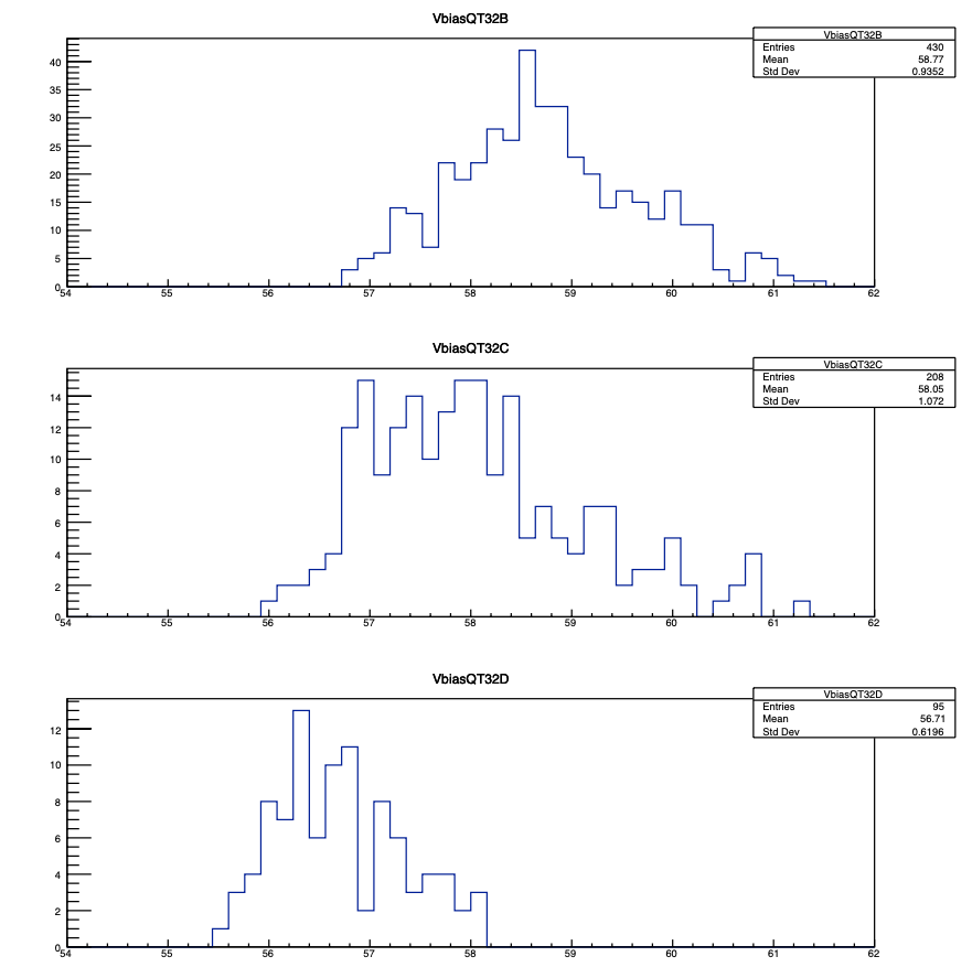
Above: the bias voltages (VSET) that will place the MIP peak at the target ADC value (140, for all tiles). The required bias voltages for tiles connected to QT32Ds are low, indicating that the QT32D itself has a high gain. The QT32B has the lowest gain, requiring higher bias for tiles connected to QT32Bs.
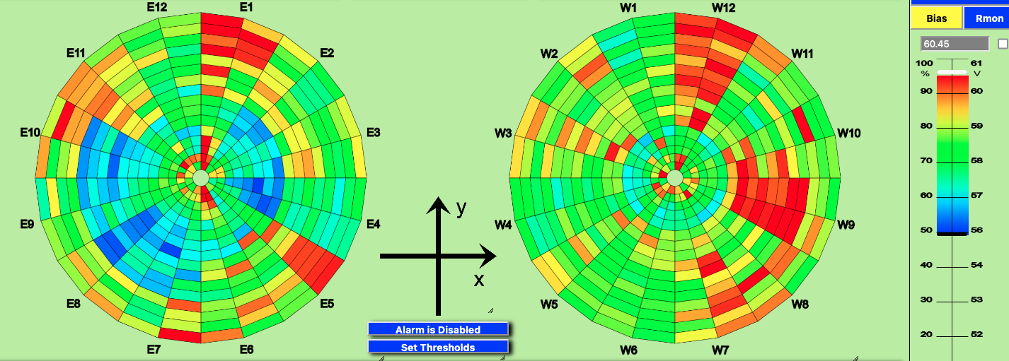
Finally, some patterns are visible when looking at voltages on the control GUI
Executive summary
After three iterations of timing scan (while problems with EQ4 and QT32Ds got sorted), the first bias scan was done on 27 May 2023. The first run with the new biases is 24147085.Some notes:
- There are 5 perhaps-dead tiles - see big pdf for details
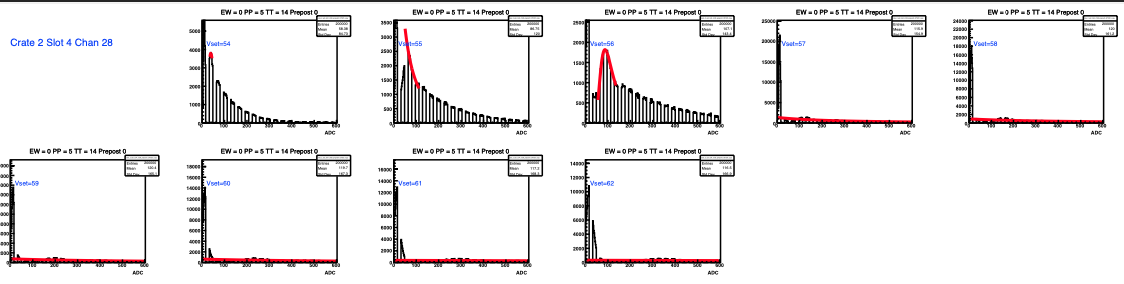
- East PP05TT14 (Crate 2 Slot 4 chan 28, QT32D) - strange
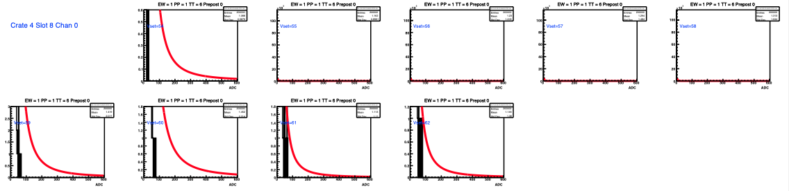
- West PP01TT06 (Cr 4 Sl 8, ch 0, QT32C) - mostly nothing
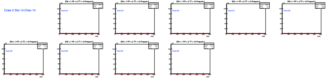
- West PP02TT10 (Cr 2 Sl 14 ch 14, QT32B) - nothing
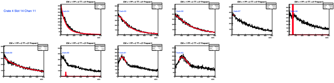
- West PP02TT27 (Cr 4 Sl 14 Ch 11, QT32B) - prob. okay but pedestal set too high?
- West PP06TT01 - we knew about this one. can see MIPs on scope, but DC offset from FEE doesn't change as we change VPED, so gives signal below pedestal in QT. FEE issue
- QT32D has larger gain than QT32C has larger gain than QT32B. We knew the latter inequality
- This year, in order to set "aggressive" zero-suppression thresholds, we are aiming to put all MIP peaks at the same ADC value (140). Because of the different gains, that means the biases for tiles connected to QT32Ds (QT32Bs) are generally the lowest (highest)
For reference
- Joey's instructions for bias scan from Feb 2023
- Mike's original discussion of the bias scan from 2018
- Rosi's instructions on how to make the "mapped" histograms .root files for scans
- Attached below are two macros:
- BiasScan.C - run this on the mapped histogram .root files
- MakeNewTuffFile.C - this takes output of BiasScan (with human fixes) and makes new bias file
- Also attached below
- the 845-page pdf file showing full details
- the new EPD_TUFFmap.txt file that sets the bias (and Vped) values
Some details
Above is shown the gain curves for all tiles (1-31) in East PP02. Each pad shows position of MIP peak in ADC, versus bias (VSET) value, for one tile. White/Yellow/Blue background means the tile is connected to a QT32B/C/D. Horizontal line is the "target" ADC where we want the MIP peak to be. Vertical red line shows what should be the VSET value, in order to calibrate that tile to the target.
It is already clear in this picture that the QT32Ds (blue) have larger gain than the QT32Cs (yellow), which have higher gain than the QT32Bs (white). Every tile is different, of course, but this trend is clear in aggregate, as shown in the plot below:
Above: the bias voltages (VSET) that will place the MIP peak at the target ADC value (140, for all tiles). The required bias voltages for tiles connected to QT32Ds are low, indicating that the QT32D itself has a high gain. The QT32B has the lowest gain, requiring higher bias for tiles connected to QT32Bs.
Finally, some patterns are visible when looking at voltages on the control GUI
- Higher biases are required for East PP01, West PP12, and West PP09, suggesting the optical coupling is less good for those connectors.
- One can also see those tiles connected to QT32Ds on the East wheel, having lower bias voltages due to the high gain of the QT32D.
Problem tiles:
Five tiles look bad (less than 1% of the EPD). One is West PP06TT01, which we already knew. The other four are below.»
- lisa's blog
- Login or register to post comments