FST testing at BNL
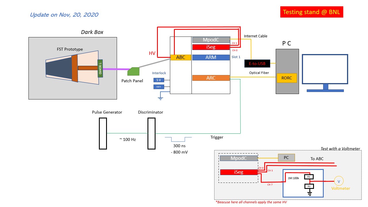
BNL test stand schematic, more details can be found here:
https://drupal.star.bnl.gov/STAR/system/files/bnl_stand_status_note.pdf
To login to FST computer(1006):
ssh -AX user@cssh.rhic.bnl.gov
ssh -AX user@stargw.starp.bnl.gov
ssh -AX user@fsttesting2.starp.bnl.gov
To login to FST computer(510):
ssh -AX user@cssh.rhic.bnl.gov
ssh -AX user@fsttesting2.star.bnl.gov
To login to softioc4 machine:
(check here if you need to access: https://drupal.star.bnl.gov/STAR/comp/onl/accessing-star-protected-network)
ssh -AX user@cssh.rhic.bnl.gov
ssh -AX user@stargw.starp.bnl.gov
ssh -AX sysuser@softioc4.starp.bnl.gov
Turn off and turn on HV from softioc4 machine:
cd users/xusun/FstSlowControl/scripts/
search and change the HV (setVoltage) in the "FstControl.sh"
bash FstOff.sh (To turn the HV off)
bash FstOn.sh (To turn the HV on)
To login to daqman machine:
ssh -AX user@cssh.rhic.bnl.gov
ssh -AX user@stargw.starp.bnl.gov
ssh -AX evpops@daqman.starp.bnl.gov
Take the data from the daqman machine:
To take the data:
bash /RTS/sl7_bin/run_fst.sh -s <events>
The data will be saved in:
/net/fst01/RTScache/data
e.g. /net/fst01/RTScache/data/fst_s01_phy01106463_dbg.sfs
Our weekly FST and slow control meeting zoom link:
The slides on the progress to be presented in the weekly FST meeting can be found here:
https://drupal.star.bnl.gov/STAR/system/files/FST04_ThermTest_Dec16_2020.pdf
Update on the hardware:
We use a thermal camera to make maps of the APV chips, the cooling line and the sensors while running the DAQ systems with triggers (no HV)
➢ Use “MikroScan 7600PRO”, calibrate at the beginning
➢ Troom=19.8 ℃; Tcoolant=22.2 ℃
➢ Start from the room temperature (T), no coolant and no power to the APV chips
➢ Power the APV chips up, HV=0V, w/wo cooling; Start a new run and measure T every 5 min
➢ Using real-time display, draw a vertical line across all the APV chips, read T on that line
➢ Also measure the T for supply/return tube and inner sensors
Update on the software:
Tonko is about to update FST01
With help of Mike Poat we will also upgrade the BNL test stand PC with SL07
This week we had a very short meeting on cooling system & FST slow control. David didn't join. Based on our last discussion he has already some progress in installing the
epics base, the sync and async packages after the software update.
Week of Dec 7 - 13, 2020: Integration Test for Cooling system
Update on the hardware:
1. Adjust the Vmax for all the Iseg module in the 2nd platform @ STAR
To adjust the Maximun Voltage, we connect the NIM cable from the front board Vmax potentiometer port to a voltmeter(see the picture as an example), then we follow the manual (see the screenshot, more details can found from the link below) to adjust the HV limit into ~150V.
After a simple calculation, we use a screw driver set the Vmax into 0.75 V (0.75V*500V/2.5V*102%=153 V). Then we did a simple test, try to set the HV using "snmp" into a very high voltage, confirmed the maximum voltage can only be set as 155 V.
In the end, we set up all the Vmax of the Iseg modules in the 2nd platform into 0.75V.
Link to the website: https://iseg-hv.com/en/products/detail/EHS

2. HV scan from 70V to 140V
3. New interlock cheater and a quick test without internet connection @510
Because our fsttesting2 machine is offline and move to 1006, we did a quick test to make sure the system still work before we move & without the internet connection(can run everything locally).
Mike help us make a new interlock cheater and we test the iseg and the "fgt_run_daq" command. All work well.
4. Move all the necessaries for the cooling test from 510 to 1006
With the help from Mike, here is a list that we moved to 1006
1) MPOD crate, with ARM, ARC, Iseg modules, and all the cables on it. (It will be good if we can have another modified ABC board, but we can also take the one we're using from the 2nd platform in STAR.)
2) NIM crate, pulse generator, discriminator modules.
3) Grey cable, Interlock cheater
4) the Linux desktop monitor and keyboard, mouse set
5) An oscilloscope with one NIM-to-BNC adapter and 50 Ohm R.
After the movement, we connect the MPOD and NIM system, test the trigger and DAQ system. All looks same as what we set before.
(Detector will be connected after the DAQ integration test)
5. Random & High frequence trigger test on STAR DAQ
With the help from Tonko, Jeff and Gerard, after they help us setup the random trigger, we go to the 2nd platform check if the trigger: 1)really looks random, 2)if there is a serious peak/tail stacking
This figure is using "infinite persistence".
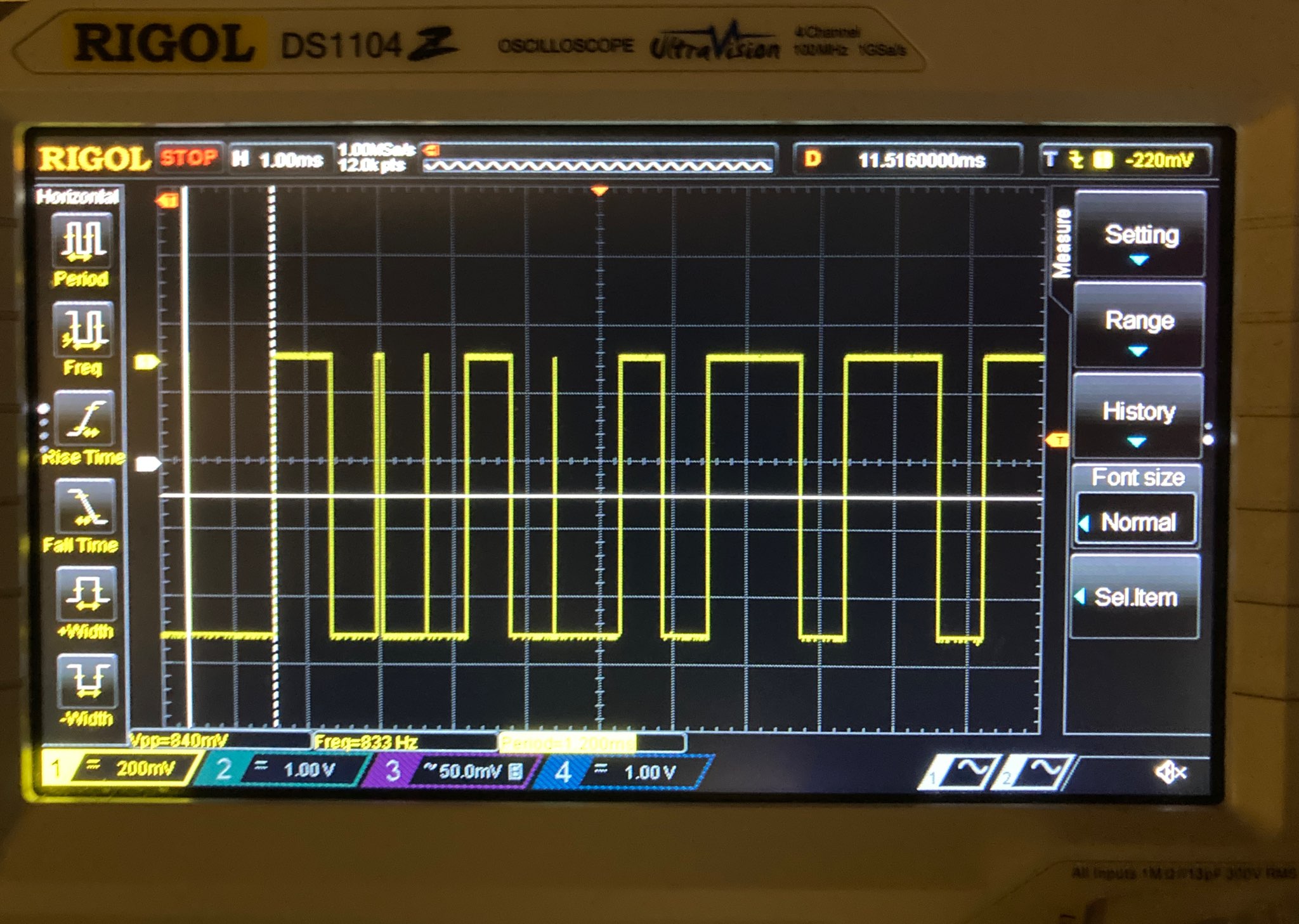
Then we go back to control room and finish the test with HV=140 V.
The whole DAQ integration test is complete.
6.
Update on the software:
Week of Nov 30 - Dec 06, 2020: Integration Test for DAQ
Update on the hardware:
1. We take the following things from 510 (physics) to 1006 (STAR)
FST prototype x 1 #04
Purple cable x 2 #06
Patch pannel x 1
Dark box x 1
Interlock Cheater x 1
BNC to Pin HV cable x 1
2. The prototype is assembled at the 3rd platform in STAR
Figure from left to right: a & b) prototype in the dark box; c) grey cable (#44) and ground cable (green); whole setup (didn't connect the purple cable to patch panel yet, for safety)
* We have 2 grey cables pull from 3rd floor to the 2nd floor. Some pins on #28 cable are bent. But #44 has no problem, so we connect the #44 to our patch panel
3. Board connection at the 2nd platform in STAR
We use the ISTMPOD02 crate, use the ARM and ARC, iSEG modules in the crate. We changed the ABC board in to the new one (Slot 2, channel 1). The old ABC board we put on the table @ 3rd floor.
We use the lower channel ARM=1 GROUP=1.
The HV cable 110 connects to the lower BNC port; the HV cable 111 connects to the pin port on the ABC board. (shown in the 3rd figure)
Use the interlock cheater took from our lab. (shown in 3rd & 4th figure)
The grounding cable (green cable, shown in the 3rd figure) is connected to the shell of the same crate. Another side is connected the Aluminum holder in the dark box.
4. HV scan from 0 to 70V (the Vmax is set to 70V)
Week of Nov 23-29, 2020: Testing FST prototype with the dark box
Update on the hardware:
1. The Dark box is ready (11/23/2020)
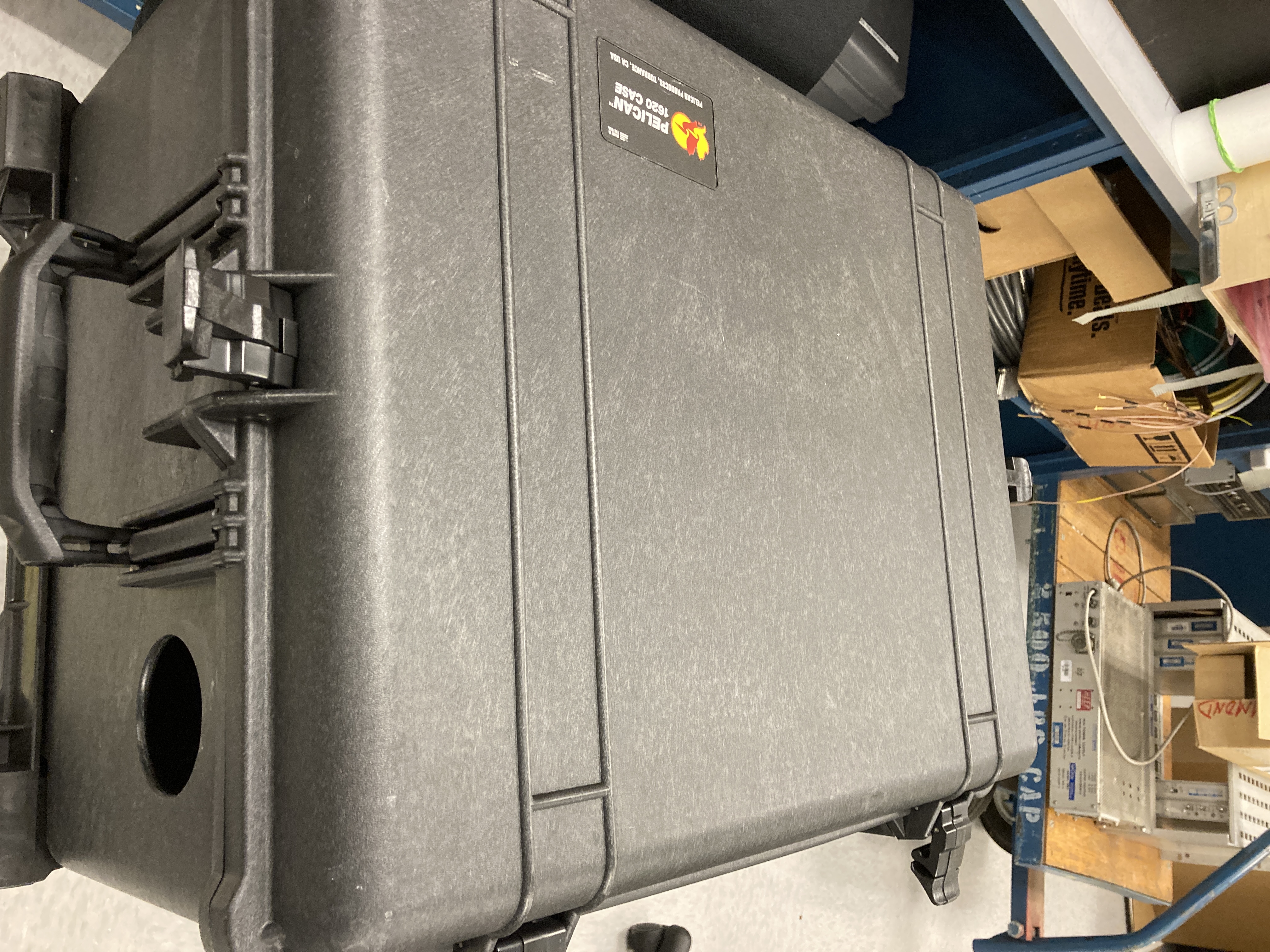
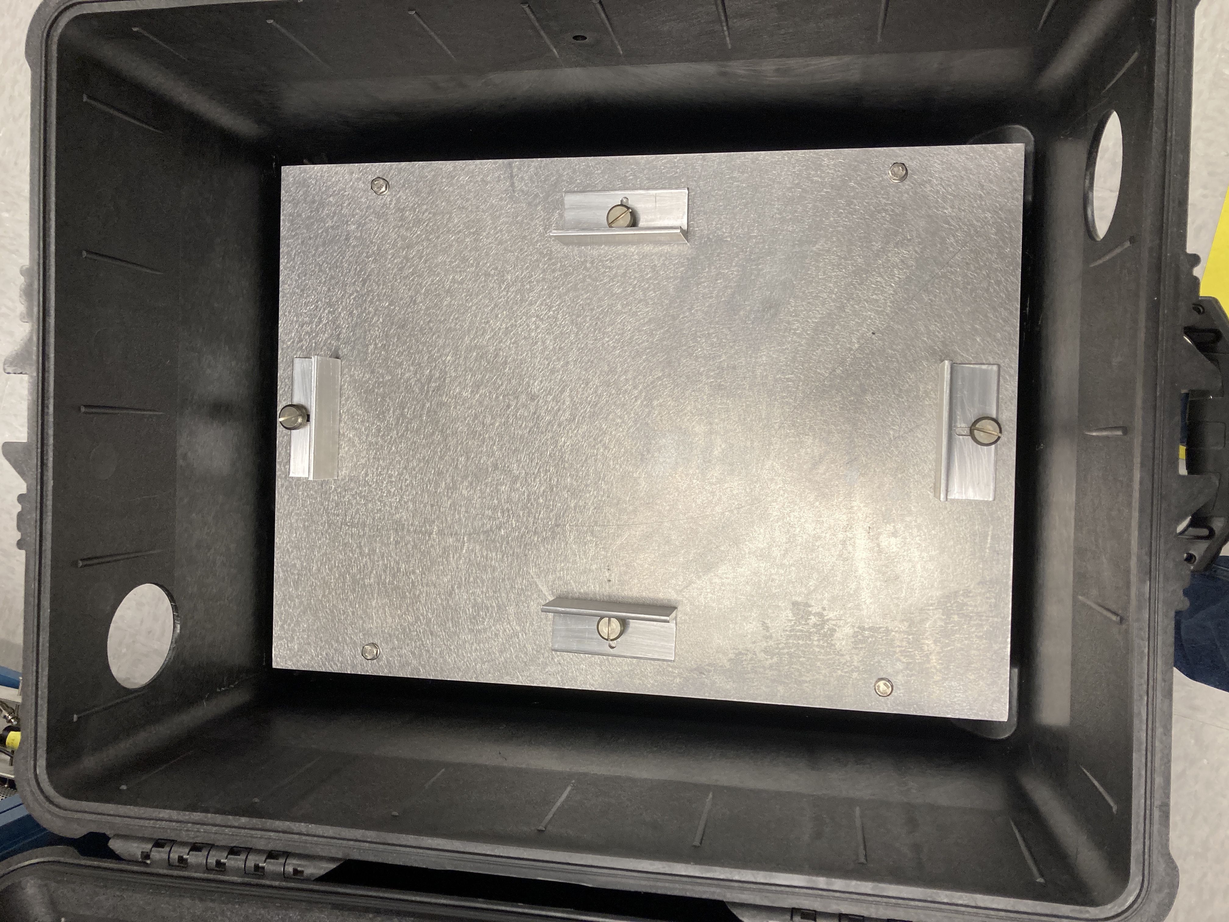
We picked up the dark box from STAR, then tried to put the prototype with the transport box inside the dark box. The dark box has flexible Aluminum plate with screws that can be adjusted
to move the supporting structures. The prototype box fits very well inside the dark box.
Two things remain that need some fixing that are as follows.
1). A holding structure to fix the purple cable with T-board inside the dark box.
2). Find a way to cover the holes for the cables to shield light.
.jpeg)
Fig (from left to right): a) Appearance of the dark box; b) Inside and the holder; c & d) With the transport box placed inside; e) Why we need a holder to support the purple cable.
2. One capacitor on the T-board cable 06 is loose, Tim helped us re-weld it.
Fig: Before and after re-welding the capacitor
3. Connect the Al plateform and T-board to the ground
Tim helped us connect the T-board ground screw to the Al holder, and connect the holder to the ground on the wall.
Note for how to ground the T-board:
https://drupal.star.bnl.gov/STAR/system/files/notes_on_making_ground_connection.pdf
4. We covered and sealed the 2 wholes on the dark box with multilayers of the non-transparent tapes.
.jpeg)
Fig. a) hole on the right side of the box; b) hole on the left side of the box(outer); c) hole on the left side of the box(inner);
.jpeg)
Fig. a&b) fix the purple cable to the dark box; c) whole setup with the black cloth covered
5. After connect the T-board and Al holder to the ground, we remeasured the pedestal for @ 0 V, 10 V and 70 V.
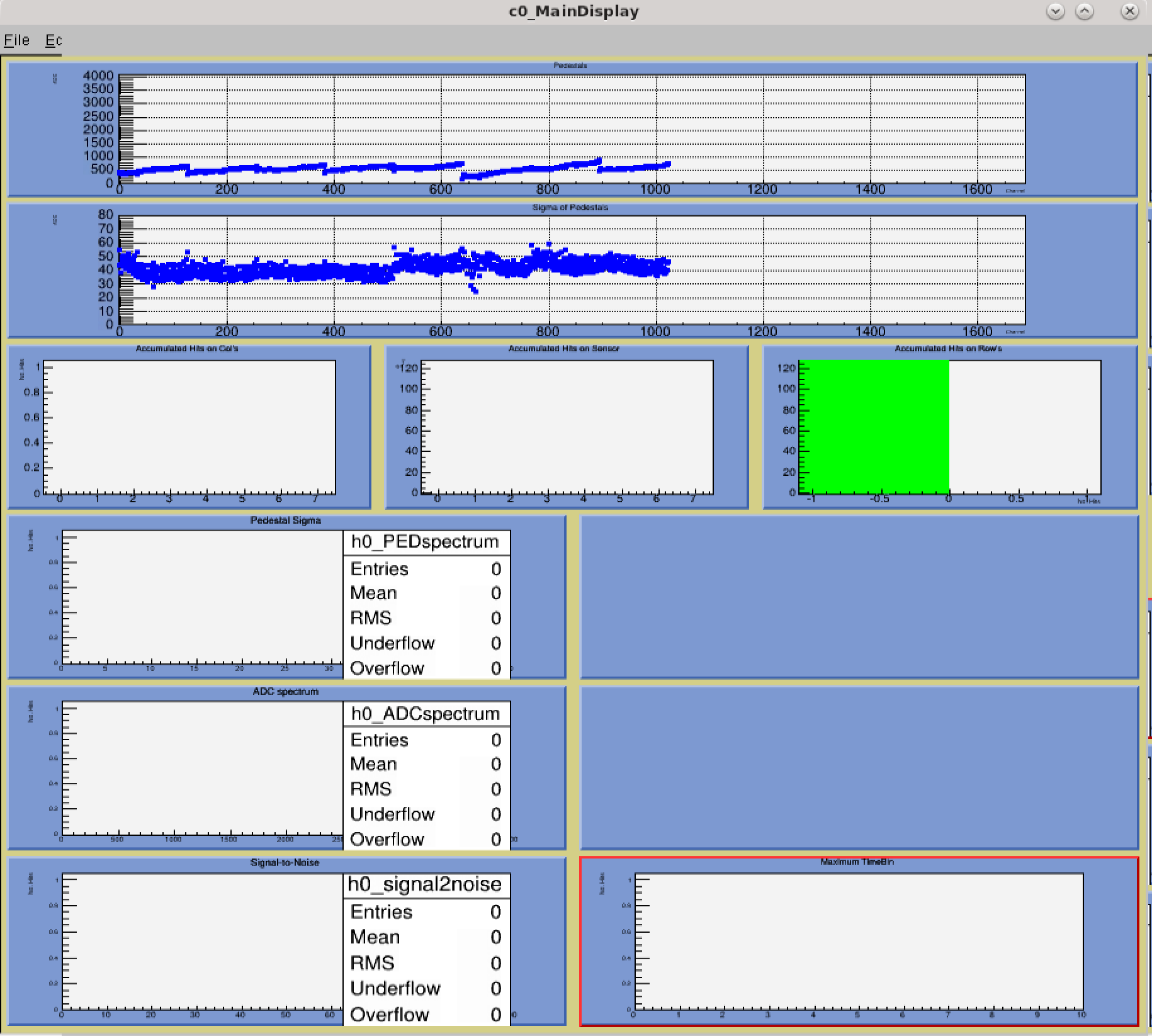
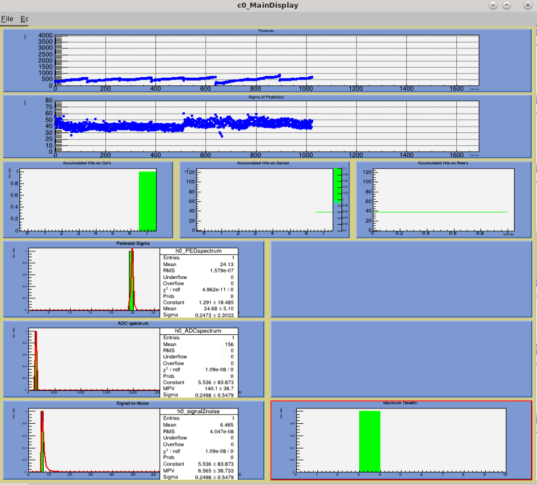
Fig. 0 V: Left, without grounding; Right, with grounding;
.png)
.png)
Fig. 10 V: Left, without grounding; Right, with grounding;
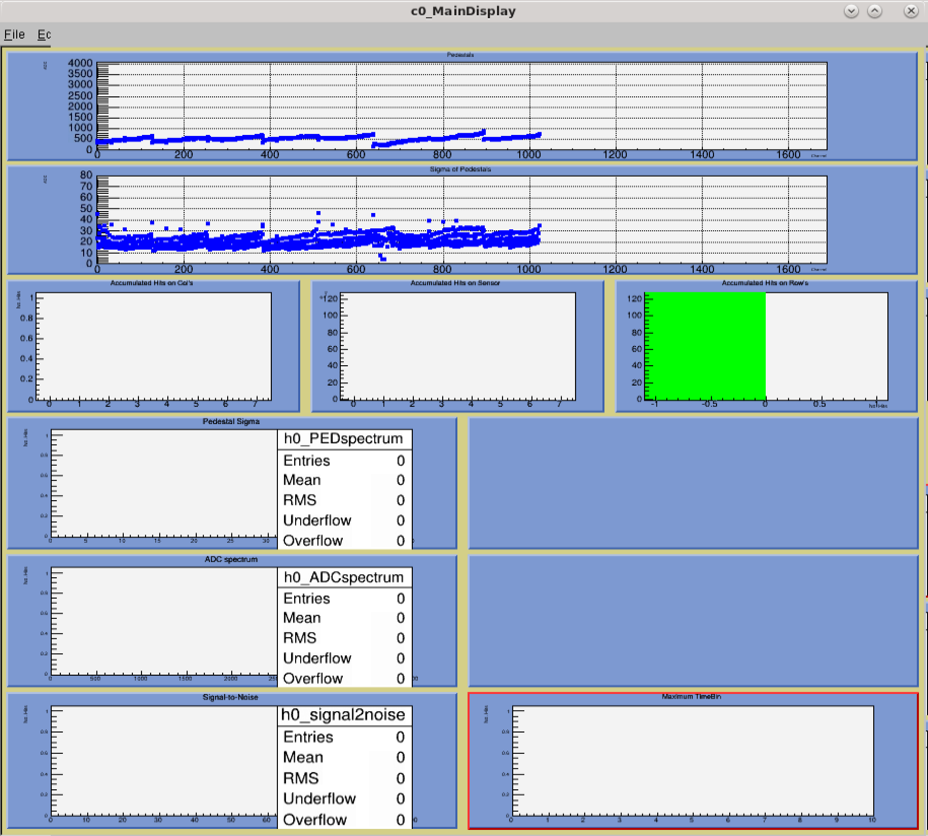
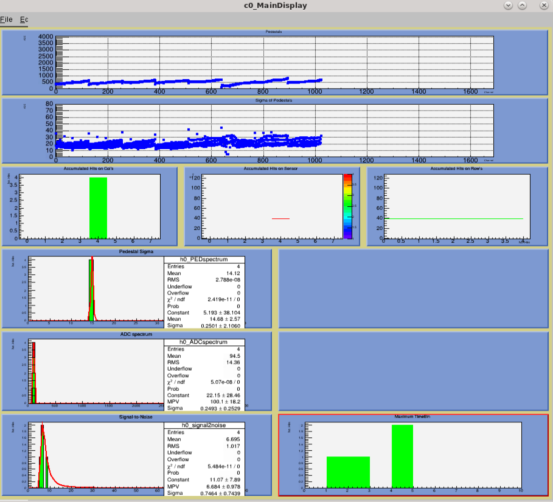
Fig. 70 V: Left, without grounding; Right, with grounding;
The plots show the noise become slightly lower as we expected.
6. We set u0 and u1 to a different voltage, after test we know:
u0 is connected to the BNC on ABC board and it is controlling the HV for inner FST;
u1 is connected with a splitter on the ABC board which is controlling the outer sensor.
Week of Nov 16-22, 2020: Testing FST prototype with BNL test stand
Link to slides presented in the FST meeting: https://drupal.star.bnl.gov/STAR/system/files/FstIntegrationTestUpdateNov23.pdf

The latest layout

Update on the hardware:
This is the procedure we have followed to setup the FST testing
1) Disconnect the hardware from IST testing system,
a) disconnect the high voltage cables
b) disconnect the purple cable from the patch panel
c) disconnect the grey cable from ABC board
2) Connect the necessary for FST prototype
a) connect new purple calbe to the patch panel
b) put the new ABC board, and also move the ARM to slot 1 to match the analysis code provide by Xu
slot 1 is the 2nd slot, RDO=1, ARM=1,GROUP=1, check the configure file in the fsttesting2 machine for more details:
/home/huyu/workspace/cosmic_testing/fst_20201118/fst_rdo_conf_yu_GroupOn.txt
c) add the high voltage cable to inner and outer FST channel
d) connect the FST prototype
.jpeg)
Fig: a) new purple cable; b) pin for the new purple cable; c) special HV cable to the slot on the ABC board (directly connect to a port on the ABC board)
Fig: d) MPOD crate; e)new ABC Board, upper HV cable connected to outer FST, lower HV cable directly on the board connected to inner FST(need to confirm when we have a HV test with the dark box)
f) Connect the purple cable&T-board to the FST prototype
3) Test the snmp script with 0 V before connect to FST prototype; read with snmp and voltmeter
more details of the code, check: /home/sunxuhit/FstTestStand/FstScrpits
.jpg)
4) Take the pedestal with no HV @ low frequency trigger (100Hz)
a) test with 0V for both inner and outer FST, use configure file from Xu (/home/huyu/workspace/cosmic_testing/fst_20201118/FTS_cosmicANDlaser_conf_Outer.txt)
use a pulse generator as a trigger (~300 ns width after the discriminator), measured the temperature with 3 sensors on the prototype ----> Check the layout on Nov 18 2020
5) Take the pedestal with no HV @ higher frequency trigger (1k Hz)
all the other setup are same with low frequency trigger
6) Set up a "temporary dark box" for the FST HV measurment
We use the card box to make a dark box for now (will get the real dark box next Monday). The box is covered with non-transparent tape for all the edges and gaps (also prevent from paper scrap fall from the top or edge). The inner surface is cleaned with a wipe.
At the end covered with a black non-transparent cloth, test with all the room light off, to make sure there is no light and over exposed for the sensors.
7) Test with no HV (0V) and HV (70 V from the iSeg output)
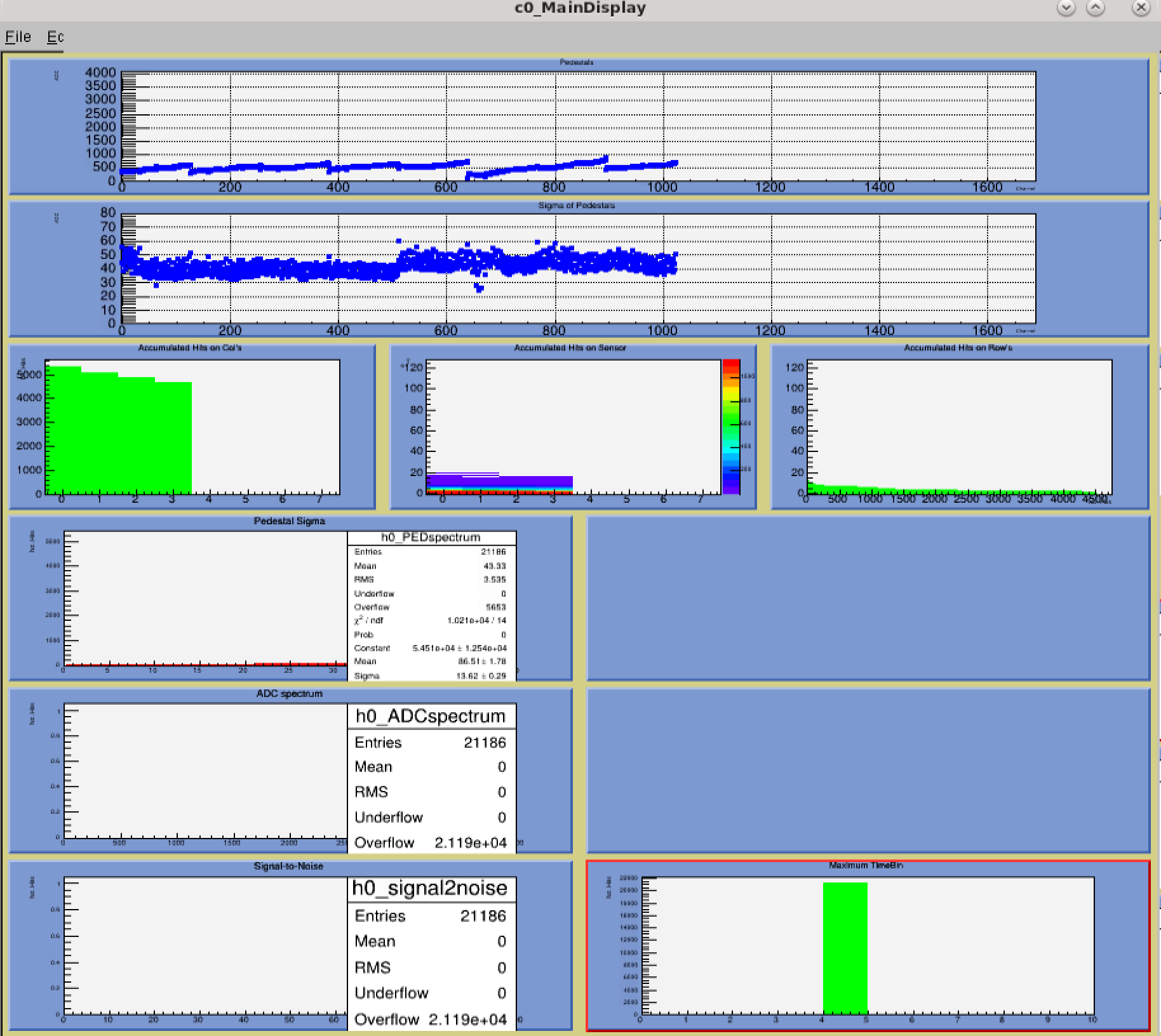
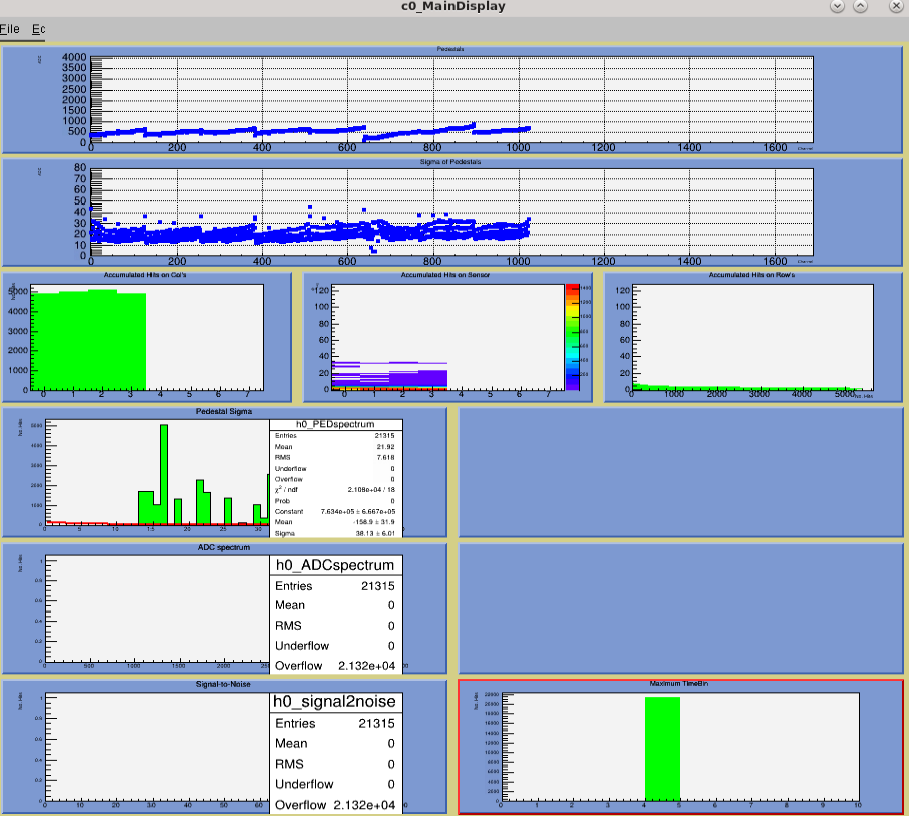
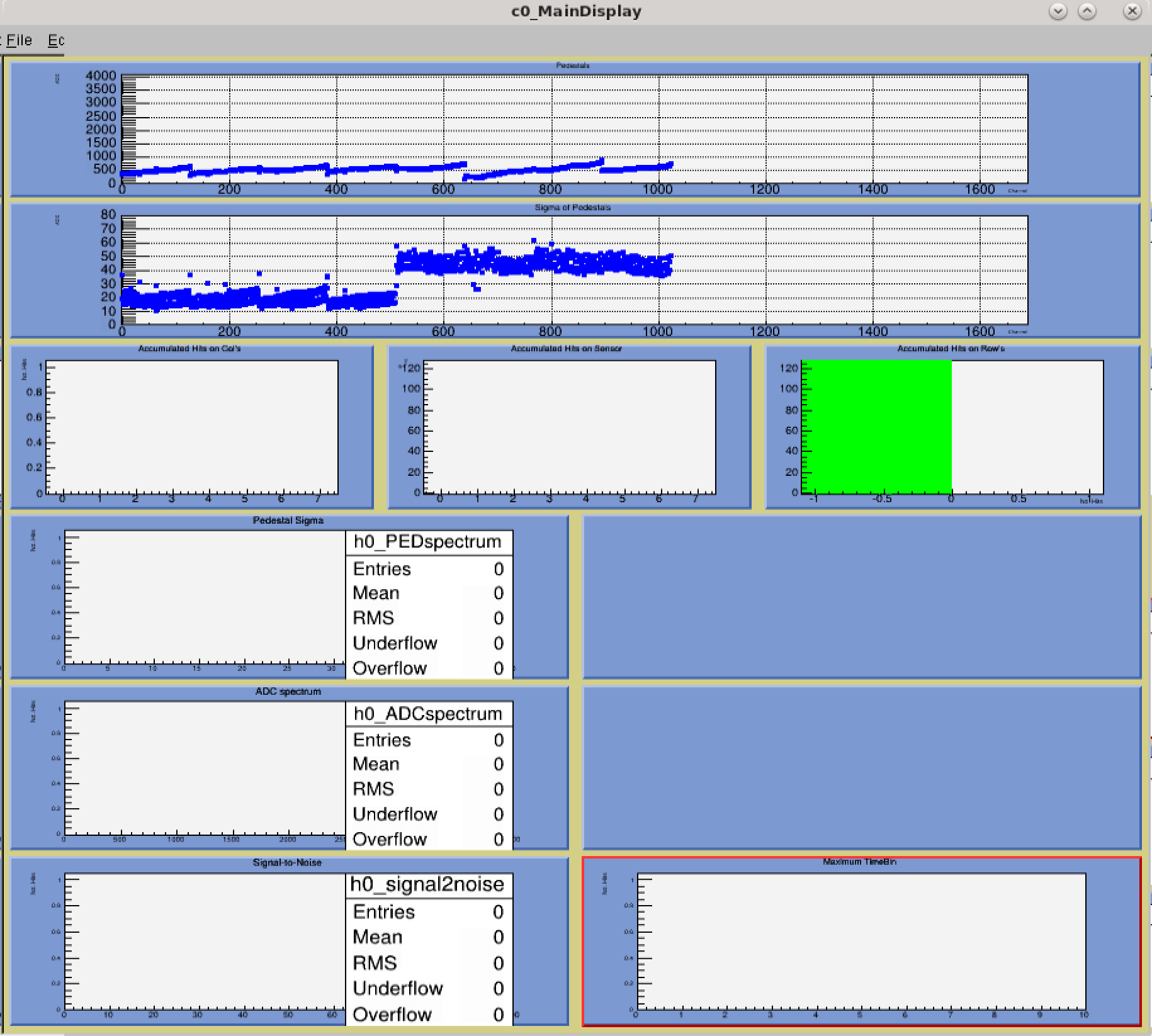
Fig: Left: Pedestal without HV ; Right: Pedestal with HV = 70 V
We can see, as we expected, with the HV, the Std Dev for each pad drops.
ps: During the test, the prototype temperature is around 24~26 read by the 3 sensors on the FST prototype.
8) Gerard help us change the time bins to 9
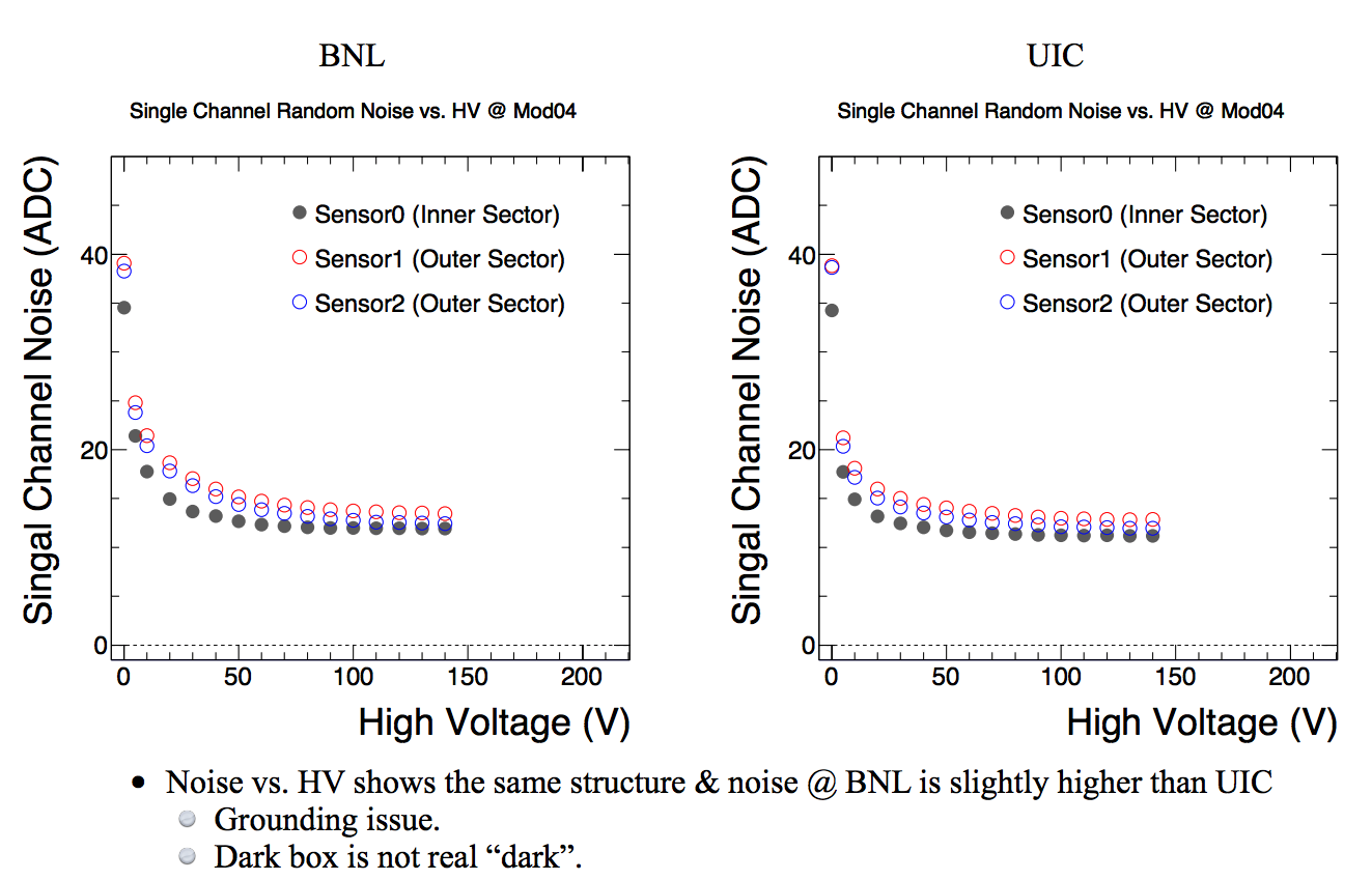
9) Voltage Scan
Trigger Frequence: ~111.11 Hz;
Path for all the data & log: /home/huyu/workspace/fst_testing/FST04/
Configure file: /home/huyu/workspace/fst_testing/FST04/FTS_cosmicANDlaser_conf_Outer.txt
Voltages: 5V; 10V; 20V; 30V; 40V; 50V; 60V; 70V; 80V; 90V; 100V; 110V; 120V; 130V; 140V
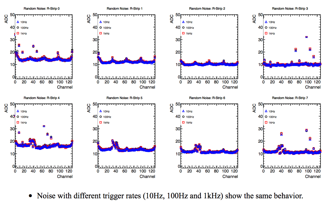
10) High/Low Trigger Frequence Test:
Test with ~10 Hz, ~100 Hz, 1k Hz with HV @ 70V
11) Configure file for 510A testing stand:
/home/huyu/workspace/fst_testing/FST04/FST_rdo_conf_510ASetup_yu.txt
We mask all the RDO, ARM, GROUP, and Temperature sensors which do not exist in our testing stand @510 1-227.
Update on the slow control:
We are trying to install EPICs on fsttesting2 machine and having issues with asyn-4-21, we discussed this with the slow control experts but not solution yet
make[4]: Entering directory `/opt/epics/synApps_5_7/support/asyn-4-21/testIPServerApp/src/O.linux-x86_64'
/usr/bin/g++ -o testIPServer -L/opt/epics/synApps_5_7/support/asyn-4-21/lib/linux-x86_64 -L/opt/epics/base/lib/linux-x86_64 -L/opt/epics/synApps_5_7/support/seq-2-1-13/lib/linux-x86_64 -Wl,-rpath,/opt/epics/synApps_5_7/support/asyn-4-21/lib/linux-x86_64 -Wl,-rpath,/opt/epics/base/lib/linux-x86_64 -Wl,-rpath,/opt/epics/synApps_5_7/support/seq-2-1-13/lib/linux-x86_64 -m64 testIPServer_registerRecordDeviceDriver.o testIPServerMain.o -ltestIPServerSupport -lasyn -lseq -lpv -lrecIoc -lsoftDevIoc -lmiscIoc -lrsrvIoc -ldbtoolsIoc -lasIoc -ldbIoc -lregistryIoc -ldbStaticIoc -lca -lCom
/opt/epics/synApps_5_7/support/seq-2-1-13/lib/linux-x86_64/libseq.so: undefined reference to `pv_value_offsets'
/opt/epics/base/lib/linux-x86_64/libpv.so: undefined reference to `caSystem::caSystem(int)'
/opt/epics/synApps_5_7/support/seq-2-1-13/lib/linux-x86_64/libseq.so: undefined reference to `pv_stamp_offsets'
/opt/epics/synApps_5_7/support/seq-2-1-13/lib/linux-x86_64/libseq.so: undefined reference to `pv_value_sizes'
/opt/epics/synApps_5_7/support/seq-2-1-13/lib/linux-x86_64/libseq.so: undefined reference to `pv_status_offsets'
/opt/epics/synApps_5_7/support/seq-2-1-13/lib/linux-x86_64/libseq.so: undefined reference to `pv_severity_offsets'
/opt/epics/synApps_5_7/support/seq-2-1-13/lib/linux-x86_64/libseq.so: undefined reference to `pv_sizes'
collect2: ld returned 1 exit status
make[4]: *** [testIPServer] Error 1
make[4]: Leaving directory `/opt/epics/synApps_5_7/support/asyn-4-21/testIPServerApp/src/O.linux-x86_64'
make[3]: *** [install.linux-x86_64] Error 2
make[3]: Leaving directory `/opt/epics/synApps_5_7/support/asyn-4-21/testIPServerApp/src'
make[2]: *** [src.install] Error 2
make[2]: Leaving directory `/opt/epics/synApps_5_7/support/asyn-4-21/testIPServerApp'
make[1]: *** [testIPServerApp.install] Error 2
make[1]: Leaving directory `/opt/epics/synApps_5_7/support/asyn-4-21'
make: *** [/opt/epics/synApps_5_7/support/asyn-4-21.install] Error 2
Week of Nov 09-15, 2020: Test control command & IST pedestal with HV
Update on the hardware:
1) Connected and tested the HV channel for the iSeg Module
.jpg)
We could use the snmp command to control the HV (e.g. snmpset -v 2c -m +WIENER-CRATE-MIB -c seCrET 130.199.60.175 outputVoltage.u0 F 60).
Although we could use "outputMeasurementTerminalVoltage.u0" to read the HV for that channel, we still want to use a Voltmeter to make sure the output voltage. We use a T-adapter, resistances box and a multimeter to measure the output voltage. The numbers shows the output from iSeg has no problem.
(a)Channel 0 (u0) with T adapter; (b)Ramping HV; (c)Multimeter(when no HV)
2) Connected the HV to IST group B
After test the HV, we connect the Channel 0 (u0) to the back of the ABC board. Because the grey cable is connected to the patch panel and the middle purple cable, so only group B is connected.
(a) HV cable on iSeg; (b) HV connected to ABC board; (c) "primitive dark cover"
3) A "primitive dark cover" for IST testing
4) Dark box will use for FST
Rahul is helpping us prepare the Dark box for the FST prototype testing. Should be similar to the UIC setup. It should have an Al plate (metal plate) that is secured to the bottom of the pelican box . It should have 4 angle brackets that can hold the box (such it is held firmly in place, but still removable).
Update on the software:
1) Simple HV control script, to turn on and turn of the HV for the IST
Scripts is in the "fsttesting2" machine.
Ramping up the voltage for IST: /home/huyu/workspace/cosmic_testing/20201113/HV_ON_IST.sh
Turn off teh voltage for IST: /home/huyu/workspace/cosmic_testing/20201113/HV_OFF_IST.sh
2) Use the default ARMDisplay code, we also compare the pedestal.
To take the data for IST, for example:
fgt_run_daq -c fst_rdo_conf_yu_GroupOn.txt -R 1 -n 10000 -L -S HV_yu_conf_10000events_test6.sfs
This test is just another "level" of testing the iSeg output HV and the data taking code (fgt_run_daq).

(a) no HV, 10000 events, pulse generator as the trigger.

(b) HV= 60 V, 10000 events, pluse generator as the trigger.
We can see, as we expected, the Std Dev for each pad drop from ~40 to ~20.
But because we only use the pulse generator as a trigger, not a cosmic coincidence, most of the events are actually just noise.
3) Install the EPICS (as a backup of FST test setup)
Update on the Slow Control and Cooling system
1) Have a weekly meeting with David, Xu, Prithwish and Yu. David will try to compile the old SC package for cooling software on SoftIOC4 during the weekends.
2) Xu and Yu are applying for permission to login and use the SoftIOC4 machine.
Week of Nov 02-08, 2020: Set up MPOD connection & test control command
Updates on the hardware:
1) ISEG HV power supply was obtained from Mike and connected to the MPOD crate, an usb cable is also attached to read the IP address.
The first adapter Mike gave us had problems. It was being disconnected -- finally it was replaced by Mike and now working fine.
Updates on the software:
In this week we had to go through the following steps to control the ISEG HV module
1) Installing the SNMP software on the fsttesting2 machine:
Although the suggestions form slow control experts were to use snmp-5.9, one the linux machine SL 6
we could not install it. We instead were able to install snmp-5.8 from this link:
https://sourceforge.net/projects/net-snmp/files/net-snmp/5.8/
We also need the configuration file from this page
https://file.wiener-d.com/software/net-snmp/WIENER-CRATE-MIB-4169.zip
WIENER-CRATE-MIB.txt Version: 4169
We are currently use SL6, so we put the txt file in this path(where we install the software)
/home/ptribedy/Downloads/net-snmp-5.8/share/snmp/mibs/WIENER-CRATE-MIB.txt
2) Setting up the IP-Address of the MPOD create and reading it through browser:
We had to struggle to set up a static IP address.
The IP address for MPOD needs to set on windows. To read and control the modules, we can use either windows or linux.
So we do all the test on windows first to check if the IP seting is correct.
In summary, the right steps to set up is the following:
a. Install the net-snmp softare and the MUSEEcontrolInstall program
b. Connect the usb cable, use the software, we set up the IP, NetMask and default Gateway for the MPOD.
c. Connect the internet cable, set the IP and netmask with windows network setting for the device. Make sure the IP are different in the last number, but the netmask match with the MPOD
Then we connect the network calbe to the linux machine
We try to use ifconfig command to set up the IP but it is changing every time if we want to run snmp command.
So we need to set up the config file like follows
[huyu@fsttesting2 ~]$ cat /etc/sysconfig/network-scripts/ifcfg-eth3
DEVICE=eth3
HWADDR=A0:CE:C8:51:01:0D
TYPE=Ethernet
ONBOOT=yes
NM_CONTROLLED=yes
BOOTPROTO=static
IPADDR=130.199.60.1
NETMASK=255.255.254.0
3) Using the SNMP command to read and control the
We follow the manual page 29-30 but things did not work
https://drupal.star.bnl.gov/STAR/system/files/WIENER_MPOD_Manual_3.2.pdf
After getting suggestions from Jarda, we finally solved the problem:
snmpwalk -v 2c -m +WIENER-CRATE-MIB -c public 130.199.60.175
Here are more details about permission and what was wrong :
Updates on the slow control and cooling system:
We had our weekly meeting (attendees Yu, Xu, Jarda, Prithwish).
1) We are going to use grid-leak and trying to understand how it works and how it can be tested on the fsttesting2 machine.
Once we have made some progress on the SNMP part we will try to get the python code and see if grid-leak can be used.
On the other hand Xu will use Jim Thomas's script. We are also trying to give Xu an access to the fsttesting2 machine so that
he can also work on this.
2) Regarding cooling systems slow control software, Jarda will collect all the old codes, try to compile and update next week.
Week of Oct 25-Nov1, 2020: Pedestal with HV & slow control for cooling system
Updates on the hardware:
Check page 17 of the manual, we are using the one with 8 channels:

2) An ethernet adapter is not available to connect the cable to the PC which will be available early next week (Monday tentatively). (Oct 25-29)
3) Upon receiving the ethernet adapter we connect the ISEG model in the lab and try to communicate with it using net-SNMP software. (Oct 25-29)
Updates on the software:
We do not want to use Window PC, we will use linux machine and set up the HV control to run in expert mode (no GUI). Here
is the plan and steps.
1) Download and Install SNMP on linux machine 1-227 from this page:
We are using the latest version 5.9 from this page: (Oct 23-29)
https://sourceforge.net/projects/net-snmp/files/net-snmp/5.9/
Just downloading the doing ./configure does the job on my mac laptop -- check Readme for instruction (Oct 23-29)

2) Download the WINER crate txt file from webpage:
https://file.wiener-d.com/software/net-snmp/
According to Jarda previously this version was used:
WIENER-CRATE-MIB-4169.zip 11-Dec-2017 16:50 22K WIENER-CRATE-MIB File
However a new version exists which is :
WIENER-CRATE-MIB-5704.zip 09-Jul-2020 14:09 25K WIENER-CRATE-MIB File
Default location on SL6 where the .txt MIB should be:
$HOME/snmp/mibs/
In SL7 it is:
/usr/share/snmp/mibs/
It is possible to set the path to MIB by environment variable MIBDIRS
and setting 'export MIBS=ALL'. The procedure is shown here:
https://docs.oracle.com/cd/E19253-01/817-3155/writingmodule-33sm/index.html
3) We already checked the procedure 1 & 2 on a mac-osx laptops & this works -- we'll do the same on the linux machine.
Once the SNMP is installed we will follow the commands on the HV manual PDF to control the crate and HV:
https://drupal.star.bnl.gov/STAR/system/files/WIENER_MPOD_Manual_3.2.pdf
Preparation for FST cooling system and slow control
The cooling system manual can be found here:
https://drupal.star.bnl.gov/STAR/system/files/IST_Cooling_System_Manual_R_1_0.pdf
Plans for the hardware:

Picture taken on 10/28/2020 on a visit to STAR to see the status of the cooling system
Changes to the Cooling systems can be found here -- all the hardware are identical to the old ones.

Controller was changed but with the same hardware with part number

Pump was changed but with same part number

Ethernet cable location -- the ports are shown where ethernet cables have to be connected
The cooling system hardware will be ready in January and connected to the systems server so that it can be accessed remotely
from anywhere. Before that if we want to access we have to arrange ethernet cables and do a test run of the software.
Plans for the software & slow control:
We have set up a weekly meeting with slow control software experts David and Jarda (we have also contacted with Chanaka by phone and he told he will try his best
to help if needed) using the same FST zoom meeting link :
- ptribedy's blog
- Login or register to post comments
