Summary of studies on the VFS parameter in the APV configuration
This blog will summarize the VFS part of our studies on APV parameter tuning.
Five APVs had the parameter VFS set at corresponding 5 values: 0, 30, 60, 90 and 120. The nominal value for this parameter is 70. Those APVs are all located on the "short" side of the quadrants.
The file used for this studies provides the actual location of the modified APVs: STAR/files/userfiles/2729/file/fgt_rdo_tune_MGAIN_ISHA_VFS_VFP.txt
The results we are showing here are obtained from a sample of approximately 1.2M events collected from run 13048050 to 13050001. These runs are normal pp200 production runs where the FGT was triggered with a min bias BBC trigger at a rate of ~17Hz.
A previous blog entry has several plots that will give you some idea of the information we extracted from that data set: drupal.star.bnl.gov/STAR/blog/ramdebbe/2012/feb/16/parameter-tuning-fgt-apvs
First a few figures that show that we can actually change the day time of the pulses. The pulses that are included in this figure are selected to be well shaped by the following conditions:
errCode == 0
chi2<2.
maxadc>600
3<timeBin of maximum < 5 ( these time values are extracted from the fits. This condition forces the pulses to be centered on our 7 time bin window )
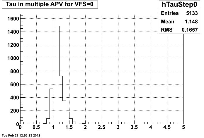
Figure 1 Tau of pulses for VFS=0
maxadc>600 maxadc>300
.gif)
Figure 2 Tau of pulses for VFS=30
maxadc>600 maxadc>300
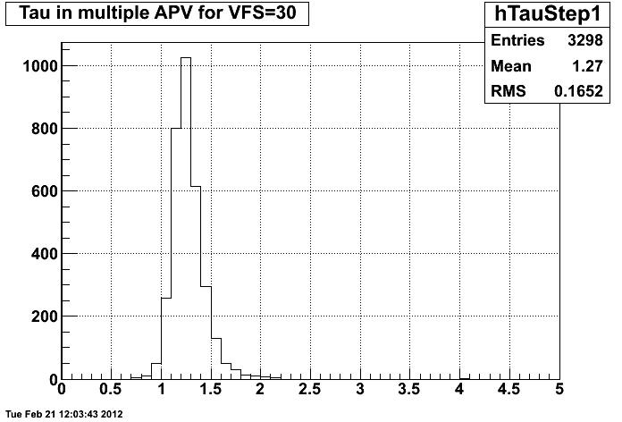

Figure 3 Tau for VFS=60
maxadc>600 maxadc>300

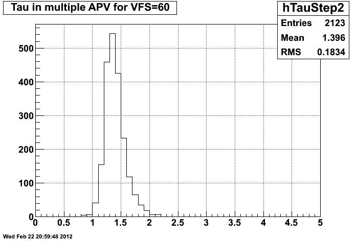
Figure 4 Tau for VFS=90
maxadc>600 maxadc>300
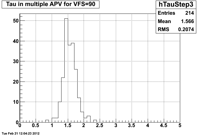
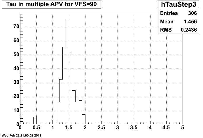
Figure 5 Tau for VFS=120
maxadc>600 maxadc>300
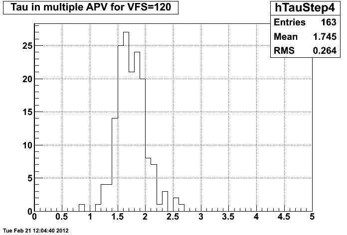
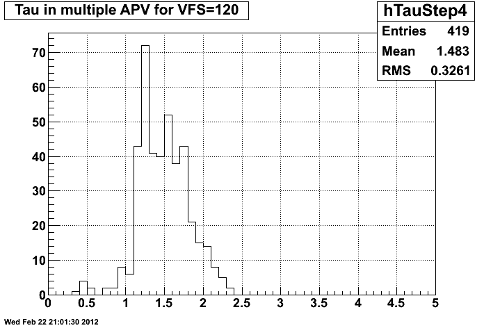
The change in the decay time is clear. What remains to be understood is The change is similar when smaller pulses are included but the distribution at
the loss of counts at high VFS. VFS=120 has become much wider.
Now that we have proof that we are changing the pulse shapes, we can start to look for a way to characterize a possible improvement in our FEE.
One of the items quoted for the performace of a read-out system is the so called signal-to-noise factor; how strong is the signal in the detector+readout system and how it affects the resolution of the readout. We will be comparing the width of the pedestal to the integrated signal from pulses whose maxima lie in narrow band defined by adcmax>700 && adcmax<900. We then display the ratio pedestalSigma/integralOfPulse for each value of VFS:
Figure 6 noise/signal for VFS=0
maxadc>600 maxadc>300

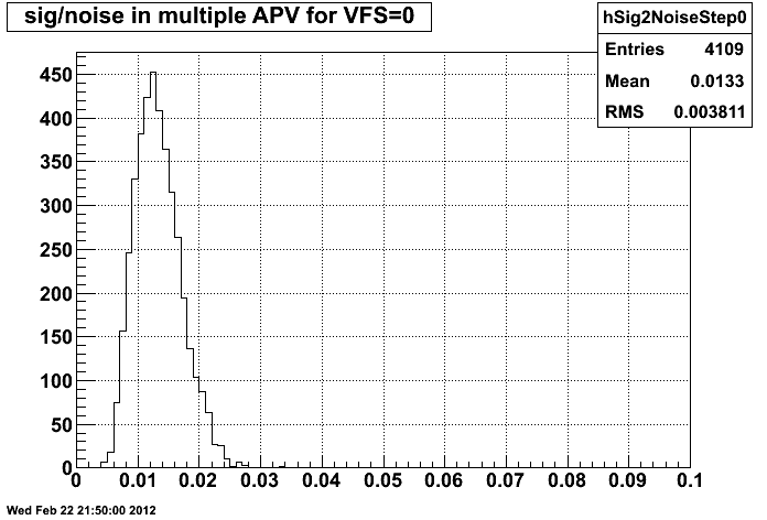
Figure 7 noise over signal VFS=30
maxadc>600 maxadc>300
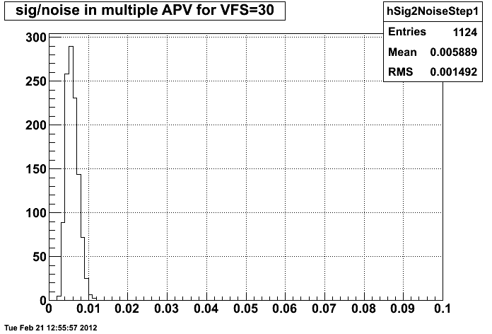
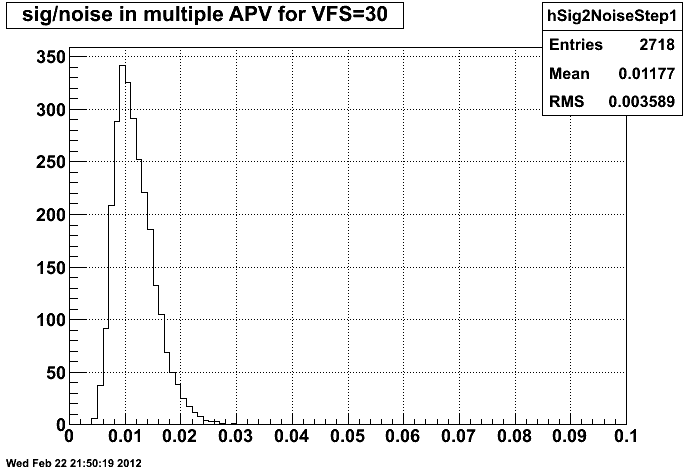
Figure 8 noise over signal VFS=60
maxadc>600 maxadc>300
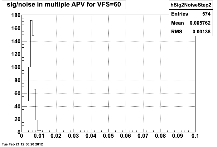
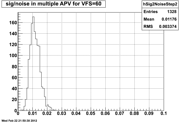
Figure 9 noise over signal VFS=90
maxadc>600 maxadc>300
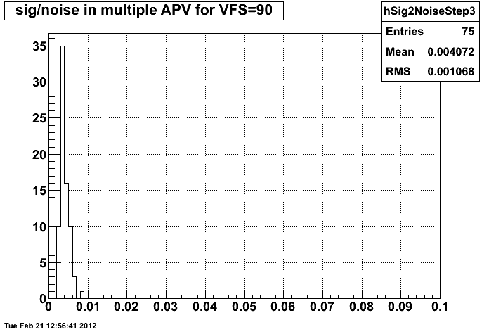

Figure 10 noise over signal VFS=120
maxadc>600 maxadc>300


Figure 11 Zoomed noise over signal VFS=120
maxadc>600 maxadc>300
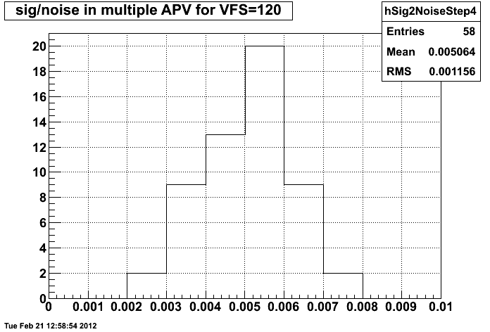
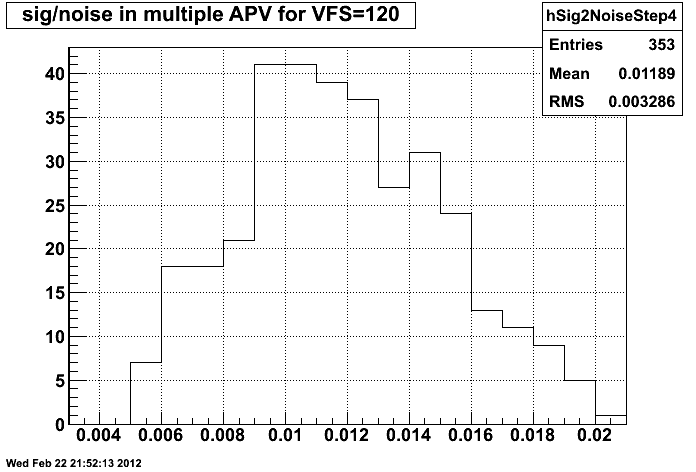
The variation on the mean value of these distributions may be trivial and it Including smaller pulses in the study doesn't change the overall picture that
is driven by the growth of the integral of the pulse as the decay gets slower. much, the distribution get wider. We now see a noise reduction of up to 18%
I want to lean more on the RMS of the distributions which must be a convolution when VFS changes from 0 to 60.
of the ADC band cut and the actual width of the pedestals. If that rough guess is
right we are seing a reduction in noise of up to 50% from VFS=0 to VFS=90
(VFS =120 would not make a difference)
Having this parameter set at the value of 70 appears a a good choice, most likely all the parameters besides VPSP are very close to their sweet spot.
I include here several summary plots produced by Len's PlotTimeShape.C
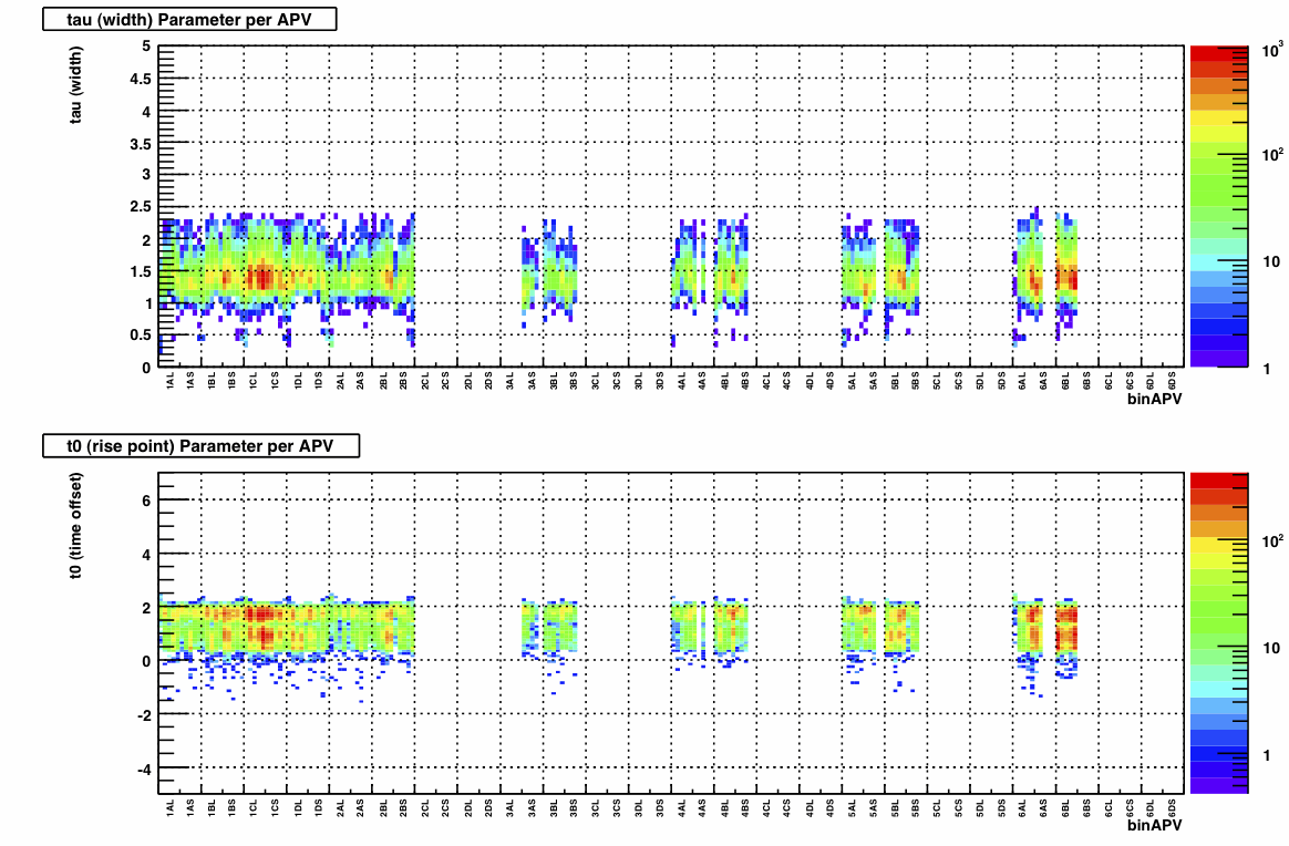
This plots are filled with the trees produced with maxadc>300
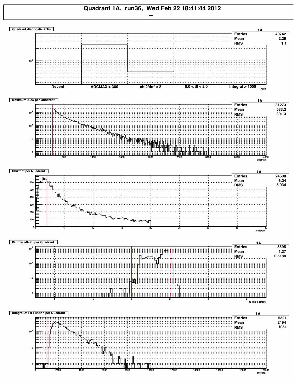
This is to show how the condition chi2<2. makes a dramatic reduction in the statistics: For that particular quadrant, only 17% of the pulses are accepted as good.
- ramdebbe's blog
- Login or register to post comments