EPD performance check after bias scan 2023
Executive Summary
Macro to make rainbow plots comparing the same tile on 12 sectors is: drupal.star.bnl.gov/STAR/system/files/TileByTile2023.txt
Macro to generate TAC Offset files is: drupal.star.bnl.gov/STAR/system/files/MakeTacOffset2023.txt
Instructions to set the TAC Offset are at: drupal.star.bnl.gov/STAR/blog/rjreed/tac-offset-files-epd
EQ3 Board 4 (0x14) Channel 13 (West PP 6 TT 1) has too weak a response (a bias setting of 62V does not bring the first Mip Peak close to 140. This is a known issue -> There is something wrong with the FEE. We see cosmics, but can't change the DC offset.
EQ4 Board 8 Channel 16 - 19 (daughter card C) is unstable.
EQ2 Board 4 Ch 24 (East PP5 TT 10), Ch 26 (East PP5 TT 12), Ch 30 (East PP6 TT 10) have a stuck 4th bit.
Bias should be adjusted for:
East PP5 TT 14 (EQ 2 Board 4, Ch 26) - I think 60V -> 57.1V
West PP2 TT 27 (EQ 4, Board 14, Ch 11) - I think 60V -> 58.9V
QTC gates were moved back (earlier) by 10 ns. The TAC Offset was determined, with the files at:
drupal.star.bnl.gov/STAR/system/files/tacoffsetsEQ1_05282023.txt
drupal.star.bnl.gov/STAR/system/files/tacoffsetsEQ2_05282023.txt
drupal.star.bnl.gov/STAR/system/files/tacoffsetsEQ3_05282023.txt
drupal.star.bnl.gov/STAR/system/files/tacoffsetsEQ4_05282023.txt
I think the online viewer mapping needs to be checked - See Figure 14.
Some of the pedestals are still high. These can be seen in Figure 15. We should check on this - it may be that a few channels need the vped adjusted so that they are in a reasonable place. (And maybe confirm that they match CAMAC off.) I wonder now whether the issue was the sigmas, when we were comparing before we probably had the bias voltages on... Which means wide sigmas. Just something to check.
Access Activities
* Check CAMAC Off pedestals - still getting warning about high pedestals - confirm that our vped settings are right. We may consider changing the vped if this is helpful. -> Dunno.
* Replace the daughter card corresponding to EQ4 Board 8 Channel 16 - 19 (daughter card C) -> We elected to wait.
* Find QTC Connector and place it on EQ2 Board 8 last daughter card. Then map:
** EQ2 Board 8 (0x18) Channel 14 - QTC -> West PP 1 TT 6 (Currently EQ4 Board 8 (0x18) ch 0 - QTC)
* Remaining spots on QTB connector in EQ3 allow:
** EQ3 Board 4 (0x14) Channel 14 -> West PP 2 TT 10 (Currently EQ2 Board 14 (0x1E) ch 14 - QTB)
What Tristan did was:
* Change DB and check Mapping again.
A QTD was also put into EQ4 to check to see whether it works.
Bias Scan Check
Mike completed the bias scan today, see drupal.star.bnl.gov/STAR/blog/lisa/First-EPD-bias-scan-Run-24 for details.
I decided to spin over the *.dat files to evaluate how well it is working. For each tile, the normalization is the number of entries. A full comparison can be found at: drupal.star.bnl.gov/STAR/system/files/TileByTile_24147089.pdf
with another run at: drupal.star.bnl.gov/STAR/system/files/TileByTile_24147090.pdf
Other than the problem tiles, there are only 2 tiles that aren't quite right:


Figure 1: West tile 1 on the left, west tile 27 on the right. The bad value in W PP 6 Tile 1 is in crate 3, board 4, channel 13.
Except, for the second run number I chose, I saw the following issue:

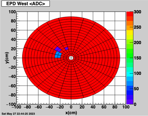
Figure 2: Additional issues in run 24147090. This was actually seen in 4 different channels PP 3 - TT6, 7, 8, 9. This also showed up in the online monitoring plot. This is associated with a QTC, probably a daughter card that is messing up. (Things went back to normal after this run.) This corresponds to EQ4 Board 8 Channel 16 - 19 (daughter card C).
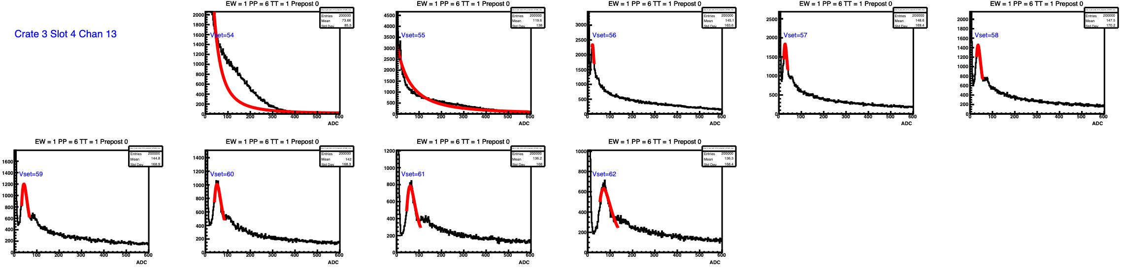
Figure 3: W PP 6 TT1 bias scan.

Figure 4: West PP 6 TT 1 bias scan. This wants to be really high.
It was set to 60V by default, I decided to bump up the bias to 62V.
The result of this change is:

Figure 5: ADC Spectra after increasing the bias for West PP6 TT1 from 60V to 62V. It did indeed get the MIP peak closer to nominal, but looks like we would need to juice it too much --> Bad FEE issue.

Figure 6: ADC Spectra showing QTD with a 4th stuck bit. EQ2 Board 4 Ch 24 -> East PP5 TT 10, EQ2 Board 4 Ch 26 -> East PP5 TT 12 (This one also needs a different bias setting, it's too high). EQ2 Board 4 Ch 30 -> East PP6 TT 10.


Figure 7(Left). One of 2 tiles that need the gain changed. Mike set this one to 60V. Looking at his blog, it seems 56V gives 100. I think this is about 240 so 35 ADC per volt. Maybe set it to 57.1V? For the right plot, see below. If we assume the same 35 ADC per volt (which seems reasonable looking at "good" channels), then maybe set it to 58.9V.

Figure 8: This is from Mike's bias scan for the right tile on Figure 7. Definitely something went weird, but it has seemed rather steady otherwise. He left it at 60, which doesn't even really make sense with what we see now. (But it seemed to be consistent with the checks I did.
TAC Offset
I analyzed run 89 since it looked ok to look at where we really were with the TACs... I think we need to back up a little bit, we're really very early in the gate. The average TAC distributions channel by channel can be seen at: drupal.star.bnl.gov/STAR/system/files/ADCTAC_24147089.pdf
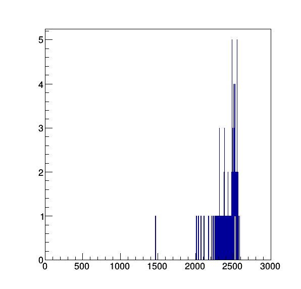
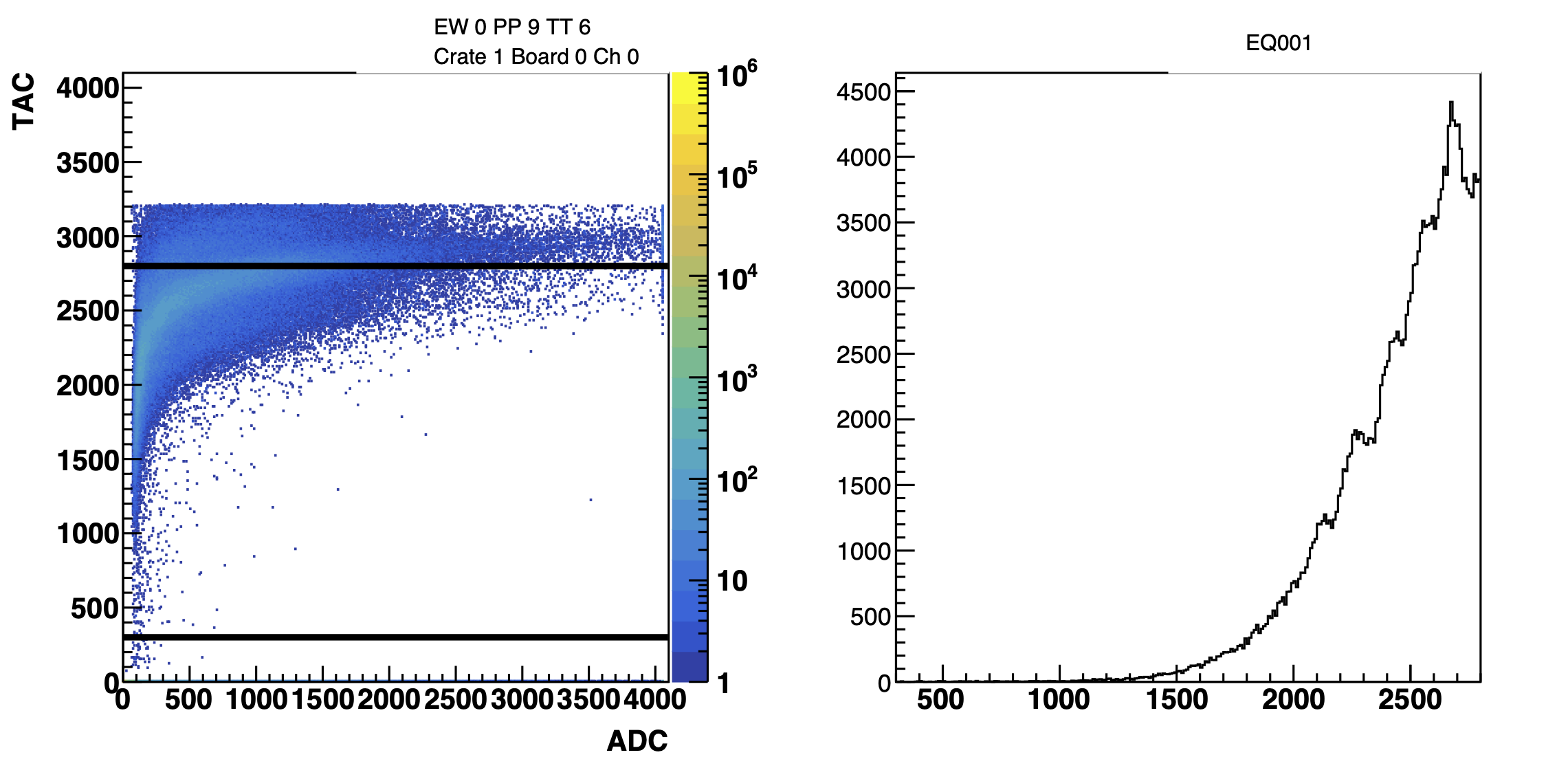
Figure 8: Average TAC channel by channel. High TAC = fastest. We see that we're basically up against where I put my edge to determine the average TAC (in order to remove outliers, I calculate the average within 300 - 2800 as shown in the middle plot). An example channel is shown above, with the middle plot showing ADC vs TAC and the right plot showing the projection onto the TAC access. Most channels were high like this.
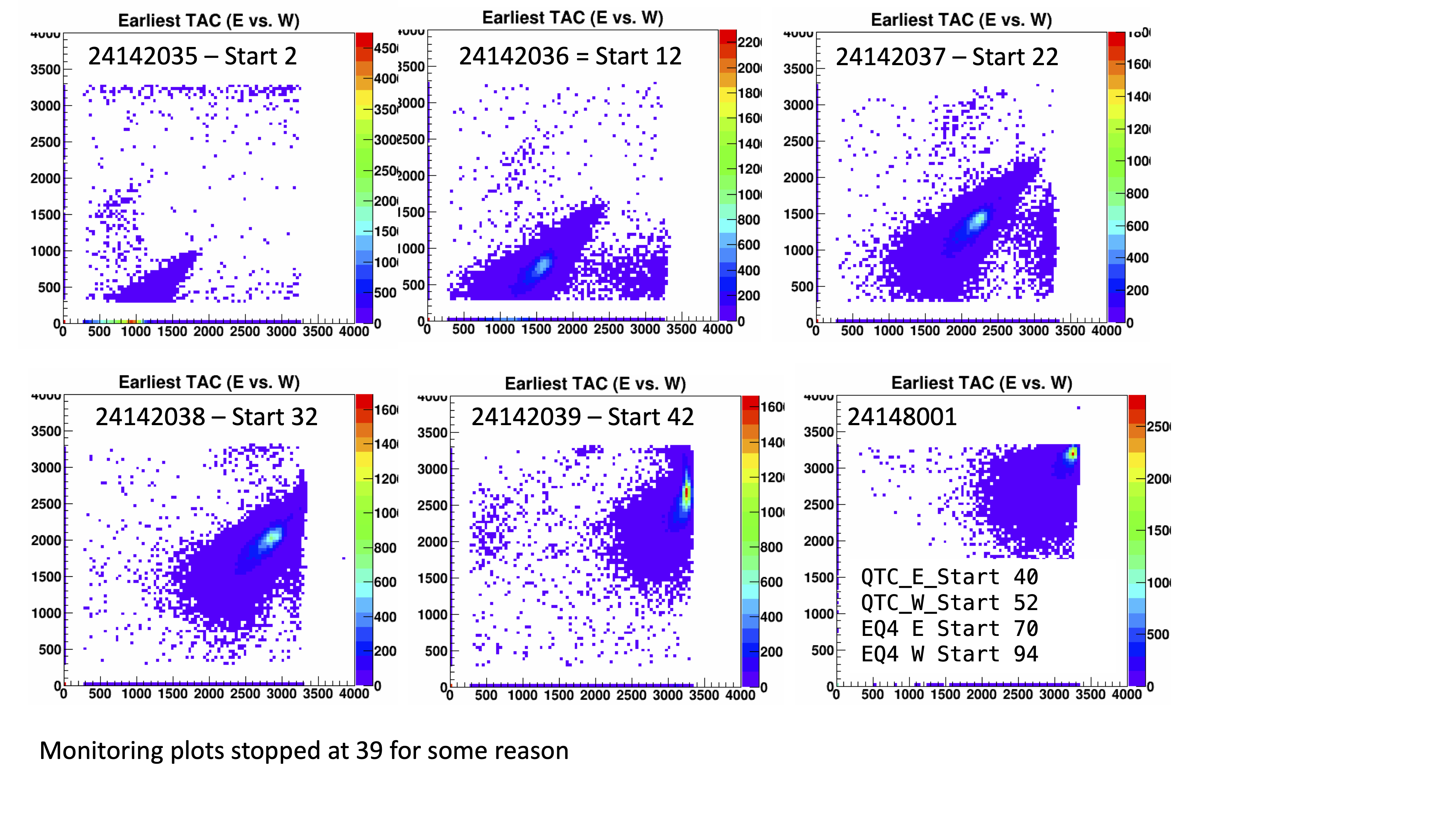
Figure 9: Timing Scan fastest TAC + Default at the start of today.
I think moving back 10 ns would be good. So I propose the following changes:
Label Old New Value
EPD_EQ4_QTc_E_Gate_End_Delay 86 76
EPD_EQ4_QTc_E_Gate_Start_Delay 70 60
EPD_EQ4_QTc_E_TAC_Stop 158 138
EPD_EQ4_QTc_W_Gate_End_Delay 110 100
EPD_EQ4_QTc_W_Gate_Start_Delay 94 84
EPD_EQ4_QTc_W_TAC_Stop 206 186
EPD_QTc_E_Gate_End_Delay 56 46
EPD_QTc_E_Gate_Start_Delay 40 30
EPD_QTc_E_TAC_Stop 98 78
EPD_QTc_W_Gate_End_Delay 68 58
EPD_QTc_W_Gate_Start_Delay 52 42
EPD_QTc_W_TAC_Stop 122 102
Changed as of Run 24148016.
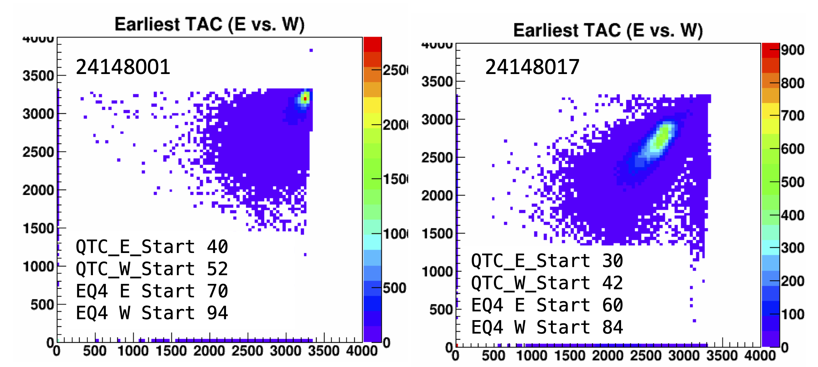
Figure 10: Showing Earliest TAC for E vs W for the default coming out of Mike's timing scan on the left, and on the right after I pulled it back 10 ns.
I used the new results to calculate new tac offsets, following the instructions at: drupal.star.bnl.gov/STAR/blog/rjreed/tac-offset-files-epd
The full pdf of all the channels can be seen at: drupal.star.bnl.gov/STAR/system/files/ADCTAC_24148017.pdf
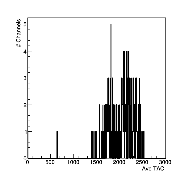
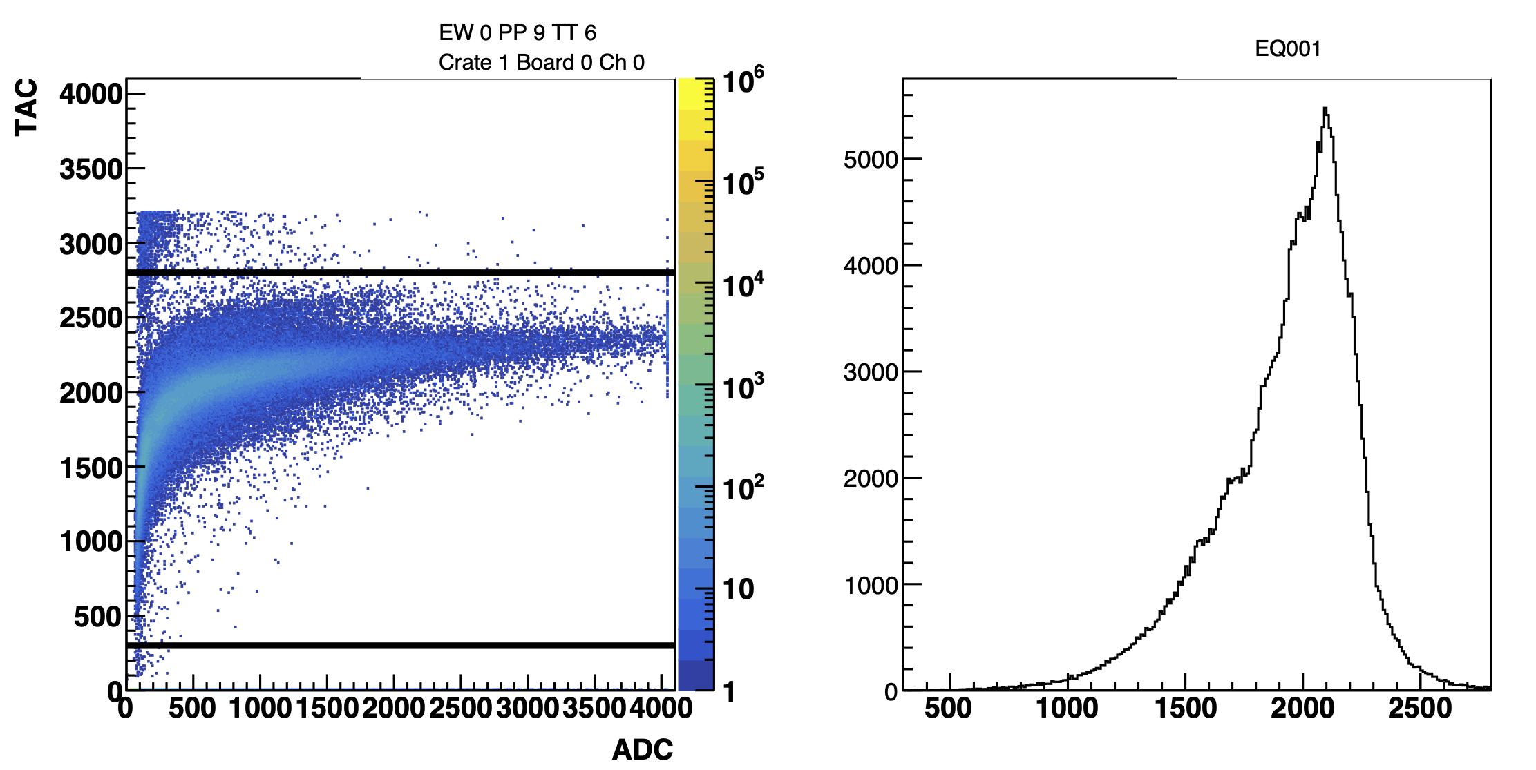
Figure 11: On the left is the average TAC channel by channel after changing the gates by 10 ns, looks reasonable. In the middle and on the right are the ADC vs TAC and TAC distributions. We see for this channel, changing the gate setting made the channel more reasonable.
Before changing the tac offsets, the settings are:
eq1_tac.dat -> /home/startrg/staruser/eq1_tac_run23_zeroed.dat
eq2_tac.dat -> /home/startrg/staruser/eq2_tac_run23_zeroed.dat
eq3_tac.dat -> /home/startrg/staruser/eq3_tac_run23_zeroed.dat
eq4_tac.dat -> /home/startrg/staruser/eq4_tac_run23_zeroed.dat
Just in case, since changing requires that these files be deleted.
The TAC offsets were applied, trying to pull the average TAC to 1370 as this was the value of the fasted channel and then checking on the results we find: drupal.star.bnl.gov/STAR/system/files/ADCTAC_24148036.pdf
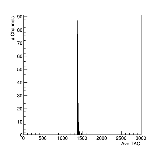
Figure 12: Average TAC channel by channel after the TAC offset. Looks really nice!
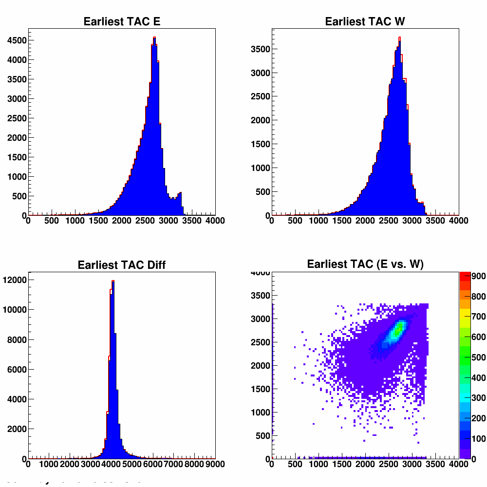
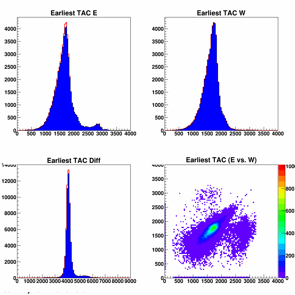
Figure 13: On the left are the TAC distributions before the TAC offset, on the right is after.
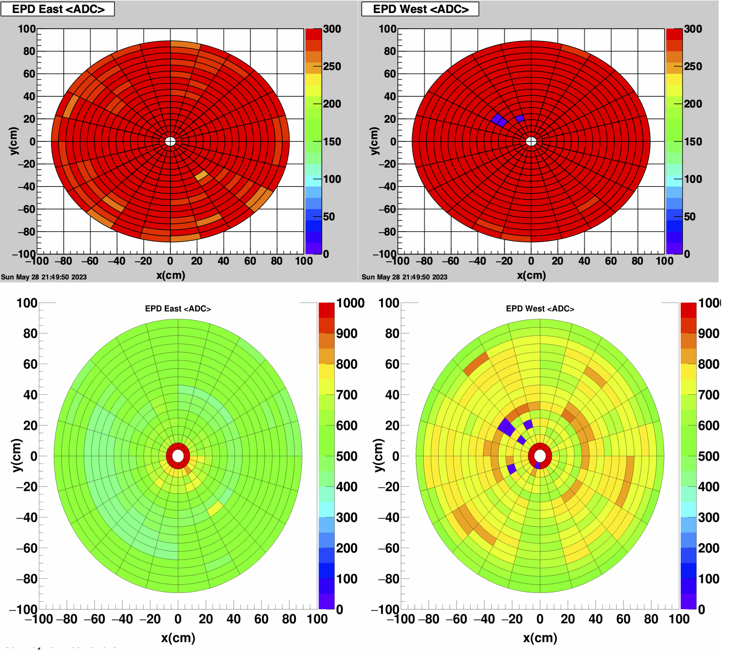
Figure 14: The QA Histogram viewer above. The online viewer below. The above seems more correct based on what I know of the mapping. Since the mapping file has to be uploaded separately, it should not be a surprise.
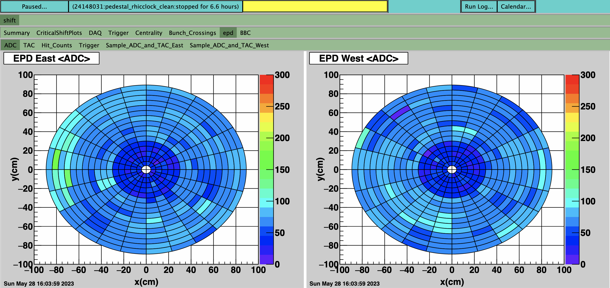
Figure 15: Pedestals for the EPD. You can see some are quite high - above 150 I believe gives a warning.
- rjreed's blog
- Login or register to post comments