Mapping EPD 2/17/2023
Executive Summary
Problems fixed prior to this latest mapping excursion were: Getting EQ4 to run (required Akio, Jack, Hank), getting the data from the crate to be included (required Akio), updating software to deal with the change. The mapping patterns were bad enough, it was clear there were still significant issues.
There were 2 issues, with a complicated interplay. One was a global change in the pedestal value from Run 22 to this run, which meant that in 68 channels the pedestal subtraction would not work correctly as the pedestal should be a "negative" value of ADC. Another was an error in the zeros TAC offset, which attempted to apply a TAC offset to QT32B boards.
After fixing the issue of the TAC offset to QT32B boards, in order to get the 7-patterns test to work, we changed:
* the Vped value of the zero file used for creating the 7 patterns from 0 to 50, which shifts the pedestals to a higher ADC.
* the Vped settings for the various levels from {0,20,120} to {70, 95, 127} .
* the threshold of the Level 2 value in the Pattern Matching from ADC = 150 to ADC = 120.
The mapping showed that some connectors were mismapped, we corrected a number of errors. The 7-pattern test for the end of the session looks like: drupal.star.bnl.gov/STAR/system/files/EPDMapping02172023_0.pdf
MISMATCH!!! ew/pp/tt = -1/1/16
MISMATCH!!! ew/pp/tt = 1/2/4
MISMATCH!!! ew/pp/tt = 1/2/14
MISMATCH!!! ew/pp/tt = 1/3/13
MISMATCH!!! ew/pp/tt = 1/6/1
Some connectors need to be relabeled. SIGH.
Details
Previous attempts can be found at:
drupal.star.bnl.gov/STAR/blog/rjreed/Mapping-EPD-12032022
drupal.star.bnl.gov/STAR/blog/rjreed/Mapping-EPD-11262022
drupal.star.bnl.gov/STAR/blog/rjreed/Mapping-EPD-09152022
The top link (December mapping) has a lot of useful information in it. The summary of the previous attempts is that adding a fourth crate broke a lot of things in strange ways. To make room for the crate, the TUFF box and TUFF Box Power Supplies were moved. We removed all of the cables between the diff-Rx and QT, rearranged the QT boards, and then recabled.
Issues
There were several issues that complicated things:
* The version of StTriggerData that includes the 4th crate is only in starnew or stardev
* A global change in the average value of the pedestals (i.e. they seem to be lower in general than before)
* An error in the Tac Offset files tried to apply the "zero" tac offset correction to a QTB, which does not have timing - this resulted in the pedestal subtraction not happening for some percentage of the tiles/events which messed up the mapping check.
* Mapping with the East side fiber bundles attached to the SiPMs but not the detector lets in a lot of light, which meant that we needed to do the mapping with bias voltage = 0.
* Changes made comparisons with previous years complicated.

Global Pedestal Offset
We compared the distribution of ADCs by level from a previous run (prior to any changes) and this run. Joey Adams wrote the original macro , I have tweaked it a little to make the following plots. See: drupal.star.bnl.gov/STAR/system/files/DrawAdcsDist.txt

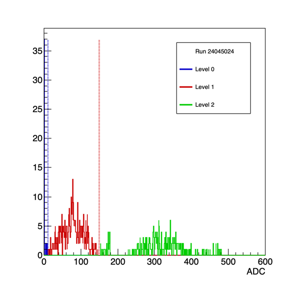

Figure 1: On the left are the distributions from the mapping test pattern 1 from Run 22. There are 2 groupings (QT32C and QT32B). In the Middle were the same distributions from our first mapping attempt on 2/15/2023. The width is much larger, and it seems that the total spread is more. One can no longer see the separate populations of Bs and Cs. It should be noted that the patterns test simply uses the second event for the test. On the right shows the result after changing the the value of the vped from 0 to 50, pushing the ADC to higher values. The "spike" problem was also solved.
Run 22:
QT32C Mean Level 1: 55.3 w/RMS = 9.49
QT32C Mean Level 2: 350 w/RMS = 8.16
QT32B Mean Level 1: 40.3 w/RMS = 3.13
QT32B Mean Level 2: 246 w/RMS = 15.7

.png)
.png)
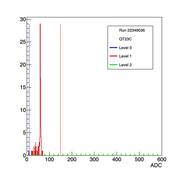
Figure 2: Run 22 values from pattern 1 broken up into QT32C (left two) vs QT32B (right two), and level 1 (red) vs level 2 (green).
Separating these out from our initial pattern runs was a mess (there was a lot of mixing, who knows what was going on).
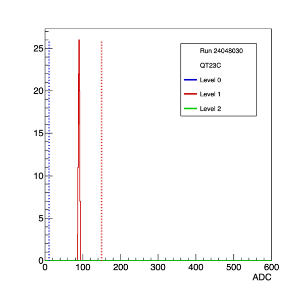


Figure 2: Run 23 values from pattern 1 broken up into QT32C (left two) vs QT32B (right two), and level 1 (red) vs level 2 (green). Key here is that we set vped to 50 for the zeros file (i.e. the starting point, this would define the zero), the spike issue was solved and we changed the threshold value from adc =150 to adc = 120.
Run 23 - WITH Vped at 0 for zero file (after fixes to spike, 2nd level threshold at 120, 24049002)
QT32C Mean Level 1: 64.3 w/RMS = 24.0
QT32C Mean Level 2: 383 w/RMS = 48.5
QT32B Mean Level 1: 125 w/RMS = 4.28
QT32B Mean Level 2: 300 w/RMS = 30.7
Run 23 - WITH Vped at 50 for zero file (24048030)
QT32C Mean Level 1: 90.3 w/RMS = 1.67
QT32C Mean Level 2: 226 w/RMS = 2.56
QT32B Mean Level 1: 62.8 w/RMS = 5.70
QT32B Mean Level 2: 162 w/RMS = 15.2
Looking at the values for vped = 50, Tristan and I decided to set the new value of the threshold between level 1 and level 2 to ADC = 120.
I had hoped to specifically be able to gather evidence of the change in pedestals, but that is difficult here given that for vped = 0, the subtraction isn't working quite correct if the pedestal should be a negative ADC. Since that is not possible, the amount subtracted varies by the true level of the pedestal. This is also why the RMS is so broad. However, it can be noted that if there wasn't a global shift, we should have seen similar results in run 22, and we did not. So this was not a result of the "spike issue".
Pedestals
There were a lot of "apparent" mismatches when we ran the mapping check on this trip. When we first compared the plots on the left and middle of Figure 1, the broader distributions indicated that the problem could be related to the pedestal in some way. First we checked the pedestals themselves (see drupal.star.bnl.gov/STAR/blog/rjreed/Mapping-EPD-12032022 for details how to do that). One example of the pedestals (run with zeros with vped = 0) is at drupal.star.bnl.gov/STAR/system/files/Pedestals_Run24047009.pdf which look reasonable (very small sigmas on most channels). An example is below. There were a number of channels with a pedestal at ADC = 1, which indicated an issue. There are 68 channels with a pedestal at 1 with vped = 0, which is a large number. In the channels where the pedestal is "below zero", the subtraction won't quite work correctly. Bumping vped = 50 for the "zeros" case, results in a distribution such as: drupal.star.bnl.gov/STAR/system/files/Pedestals_Run24048020.pdf

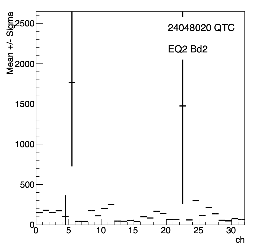
Figure 3: Pedestals by channel for a single QT32C board. (Left) For vped = 0, the pedestals look reasonable in that they don't have much width, but there are a number that are at 1. This indicates that the "true" pedestal is below the range (ADC has to be positive). (Right) For vped = 50, we see that there are no longer any pedestals at ADC = 1, though we see this does some weird things in some of the channels. It should be noted here that these are largely the TAC channels - which it is unclear to me how these should depend on vped at all.
Pedestal Subtraction
We also checked the width of each individual channel in the pattern distribution themselves. (How to do this is outlined in: drupal.star.bnl.gov/STAR/blog/rjreed/Mapping-EPD-12032022). The pdf of all channels is at: drupal.star.bnl.gov/STAR/system/files/Compare_big_02172023_wcr4.pdf. An example is below.
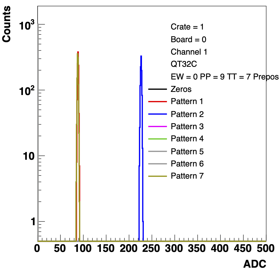
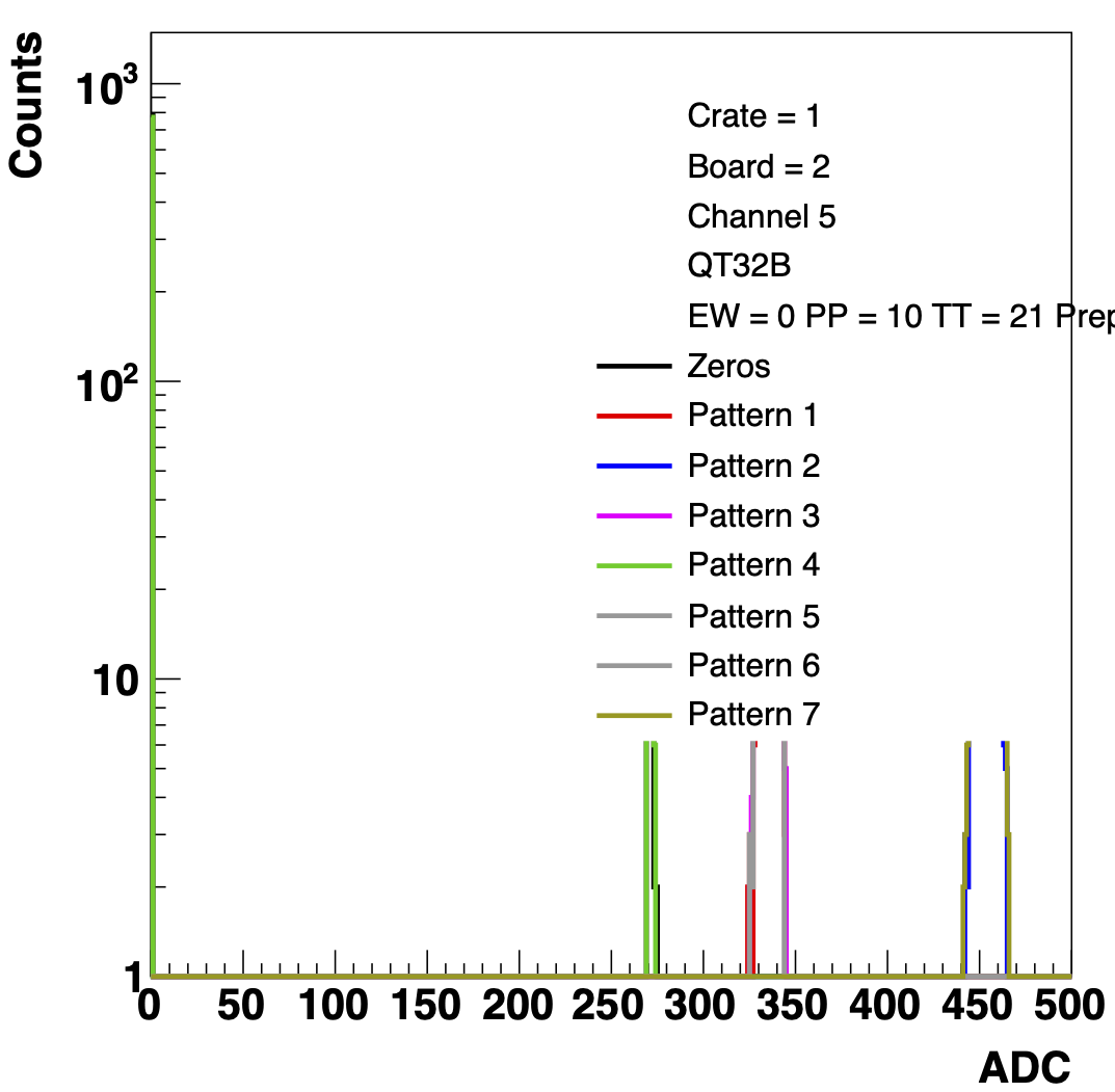
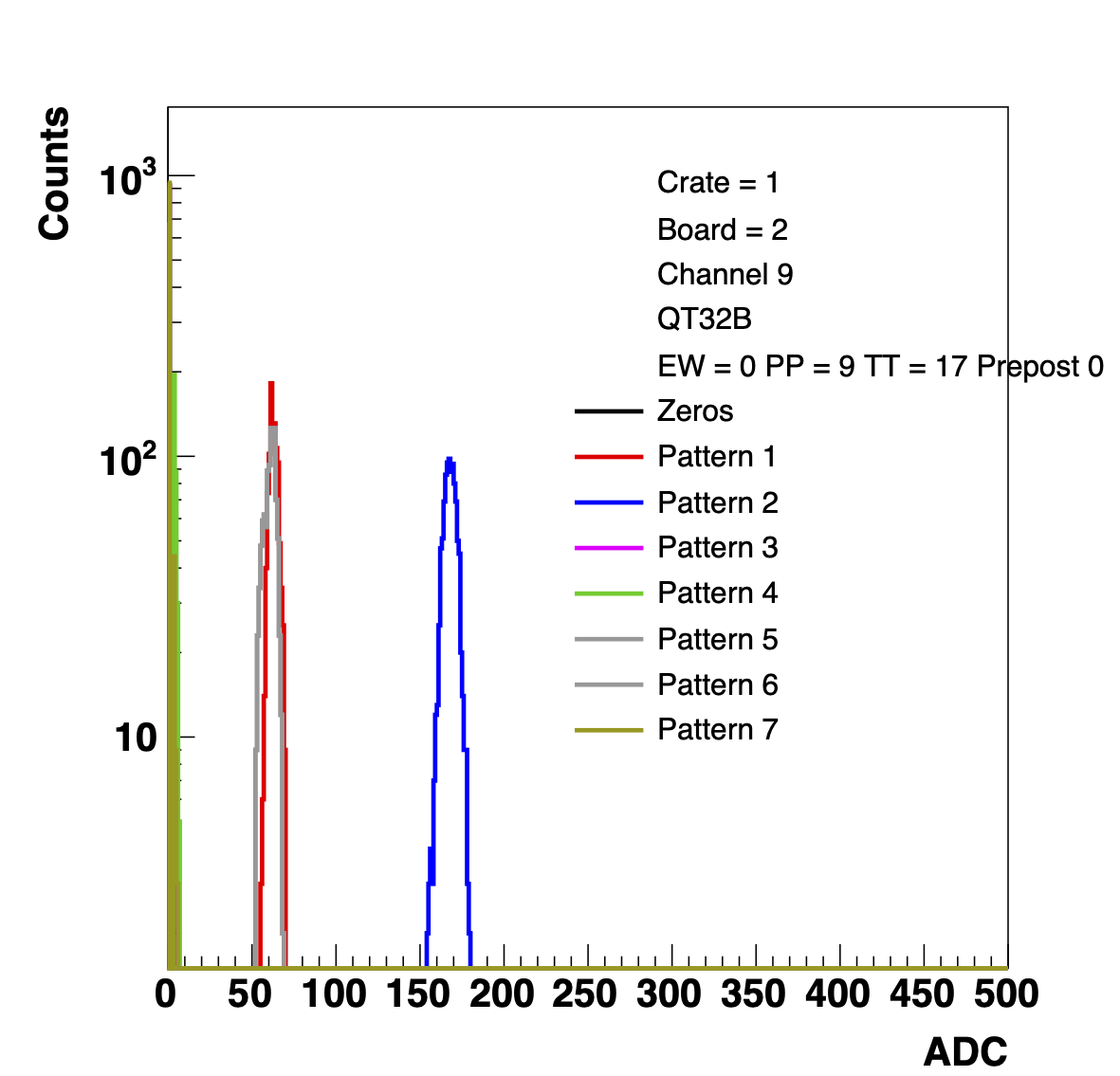
Figure 4: ADCs from PedAsPhys runs with a zero file at vped = 0, before fixing the spike issue. The plot on the left shows a "normal" distribution with respect to the values of the pedestals. The plot in the middle demonstrates the "spike issue" - i.e. no pedestal subtraction. The plot on the right shows an issue with a pedestal that looks like it should have been a negative number.
Mike and Tristan established via scope that the change in mV coming out of the diffRx was linearly proportional to the vped changes on the FEEs on a few channels, picked from both "normal" and abnormal channels. This indicated that there wasn't a general problem with the SiPM->FEE->diffRx. One thing we had been worried about was voltage sag, as the power supplies (and TUFF box) had been moved to make room for the 4th crate, and about 20 ft of extension was required. We had also increased the power output of the PS, so this was a possible culprit that was ruled out. The "global shift in pedestals" couldn't quite explain this behavior - though we were certain that such a shift was happening.
We then took a pedestal run (pedestal rhicclock clean), followed by a pedAsPhys. If things were working correctly, the ADC distribution from the pedAsPhys runs should be completely at zero with the occasional count at ADC 1 or 2. We saw otherwise, as shown in:drupal.star.bnl.gov/STAR/system/files/Compare_big_ZeroCr4_02172023.pdf with an example below.
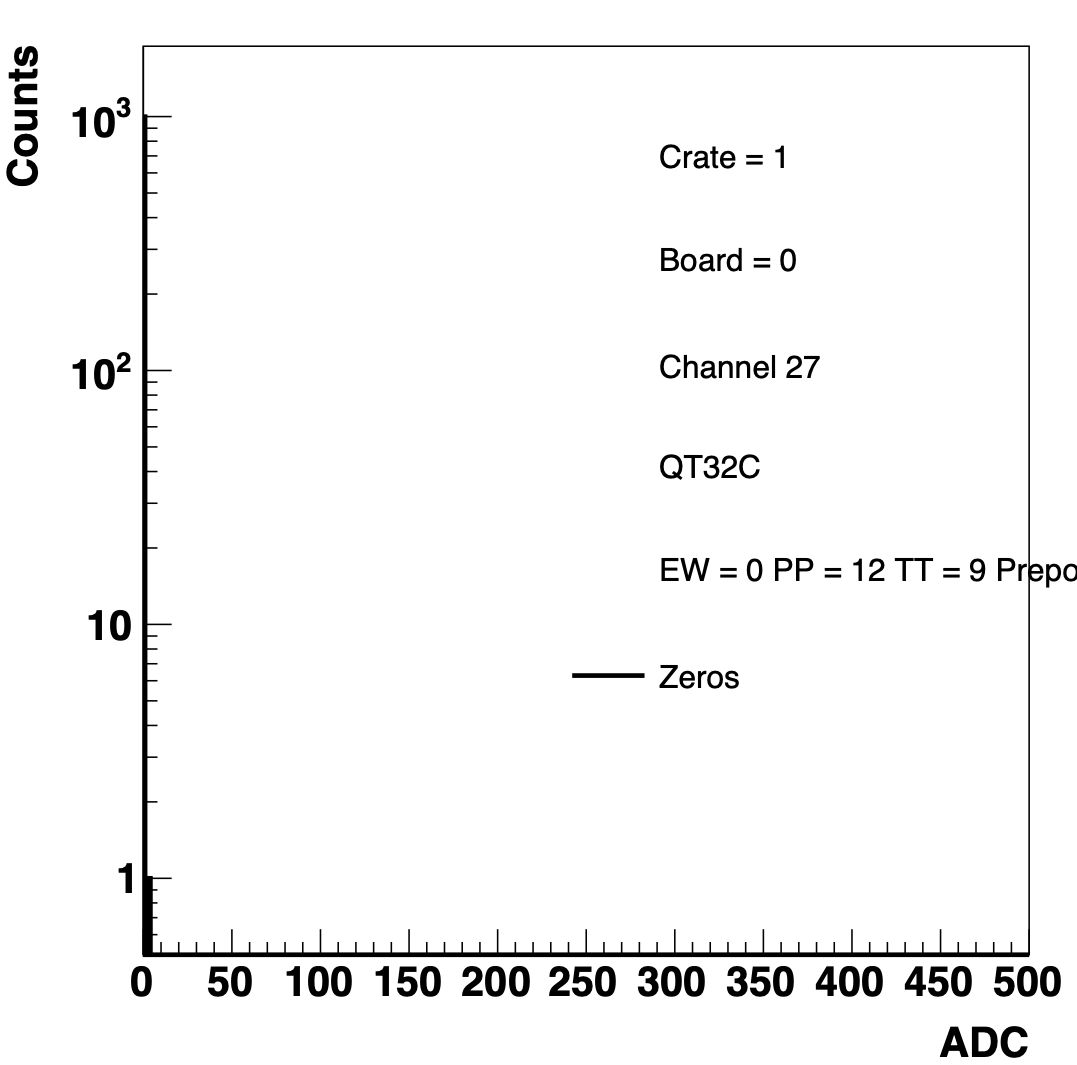
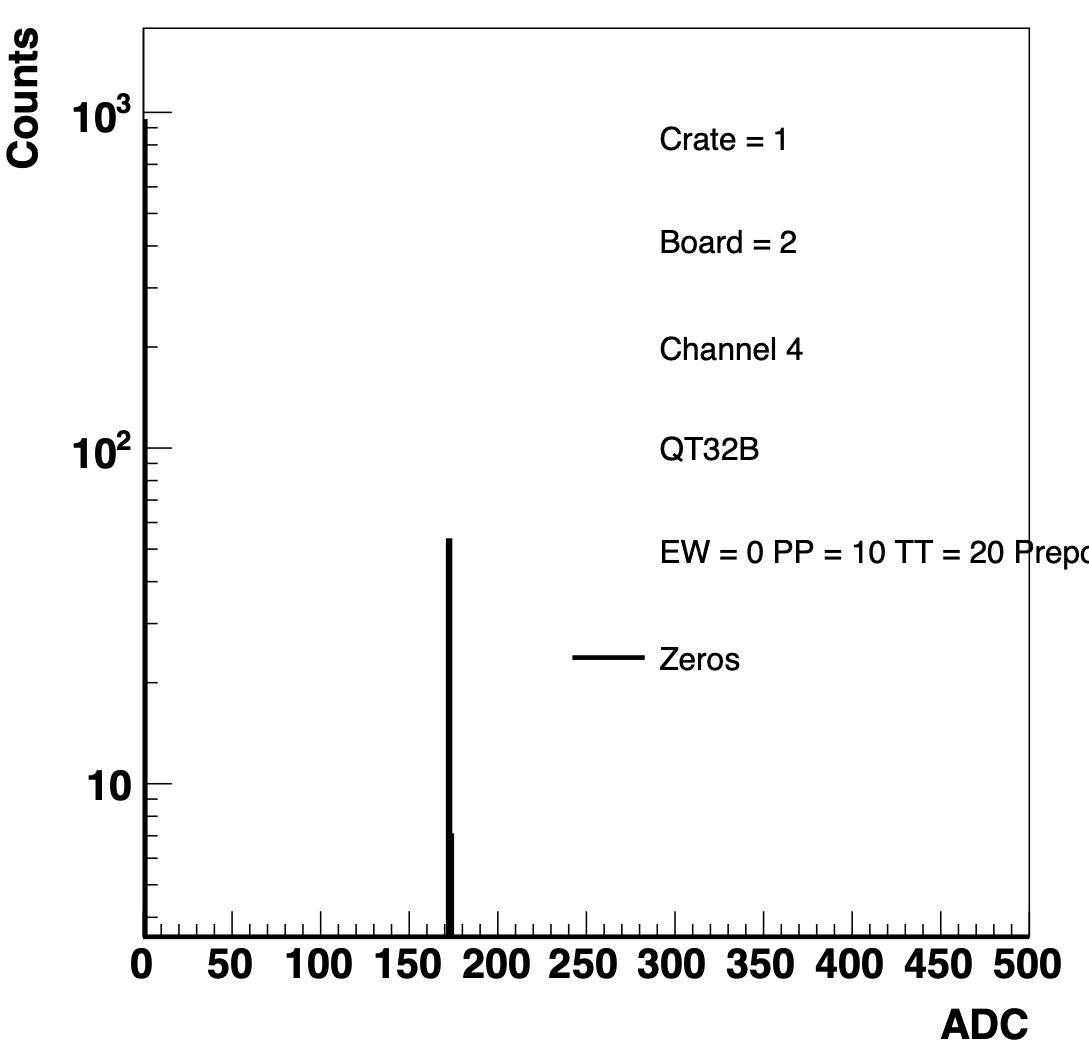
Figure 5: PedAsPhy run taken immediately after a pedestal rhicclock clean. All channels should look like the one on the left. Instead, some looked like the one on the right. The ADC of the spike corresponds to the ADC value of the pedestal.
The problem shown on the right side of Figure 5 was very vexing. First, it didn't occur on all channels, only some. It also didn't occur all the time, there were still counts at ADC = 1. However, it wasn't a case of it bouncing back and forth because when we looked at the patterns, we never saw 6 spikes in a channel, which is what we would expect to see if the pedestal subtraction was only working some of the time, and not working the rest. We noted that the "bad" channels came in groups of 4 and were always on the B-boards. This was weird, because the daughter cards of the QTBs are 8 channels (unlike the C boards with 4 channels of ADC and 4 channels of TAC).
The issue is that it turned out that the zero tac offset file created by Jack has an off by 1 error. Chris Perkins, in response to Mike's summary of our issues (at this point we had given up on solving the issue ourselves), noted that this is exactly what would happen if a TAC offset were being applied to an ADC channel. So I looked at the files, and saw that this was the case. It should be noted here that the trigger system has multiple ways of counting the boards depending on what one is doing, much to my dismay. After correcting the zero file, we no longer had the spike problem. We still had the overall shift in pedestal value, so we changed the default vped for the zeros case and we changed the threshold between level 1 and level 2 from 150 to 120.
Mapping with a working system!
Tristan and I decided that with the system working, we should continue the mapping quest in order to earn exp and level up as physicists (plus bragging rights). So we ran the pattern test and found: drupal.star.bnl.gov/STAR/system/files/EPDMap_wSomeError_02172023.pdf where the first page shows a PedAsPhys with the "zero" setting. Apparently we were very tired when we did the West side. So we corrected the connectors reran the system, and then got food and beer while waiting for HPSS. (Why oh why can't we easily download files from the system right after they were taken?!)
The final result can be seen at: drupal.star.bnl.gov/STAR/system/files/EPDMapping02172023_0.pdf
MISMATCH!!! ew/pp/tt = -1/1/16
MISMATCH!!! ew/pp/tt = 1/2/4
MISMATCH!!! ew/pp/tt = 1/2/14
MISMATCH!!! ew/pp/tt = 1/3/13
MISMATCH!!! ew/pp/tt = 1/6/1
To my dismay, apparently my group can't label things properly and so a number of the connectors will need to be relayed. :-(
- rjreed's blog
- Login or register to post comments