Advanced Geometry Interface for GSTAR
Pavel Nevski, 28 April 1996
Abstract:
A modified GSTAR framework includes an advance detector geometry description, supported by a preprocessor and a dedicated library. It automates the detector response and provides a data handling mechanism with a built-in documentation and database support.
1 Introduction
A good understanding of the STAR performance requires many GEANT-based simulations of the detector and its environment.
A fast and reliable way to implement these systems in GSTAR is to use a dedicated geant parser (Fortran preprocessor) which is supported by an Advanced Geant Interface library called AgSTAR . Maintaining the GEANT specific tables of materials, volumes, hits descriptions, etc and insuring the internal consistency of most of the actual parameters of the GEANT routines, it significantly reduces the amount of information the user needs to worry about and improves the robustness of the program. Here we describe the main rules and features of this program.
2 GEOMETRY DESCRIPTION
The geometry of each STAR detector in GSTAR is described in a single module. Modules are written in the geant language and translated by the parser into conventional, well commented Fortran subroutines compiled and linked with the rest of GSTAR libraries. A module consists of the module header, the data definition part and of a number of blocks, each describing one GEANT elementary volume and its content.
2.1 geant language
The geant language is a Fortran extension oriented to the GEANT application. In addition to Fortran statements, it contains a number of geant statements in the form:
OPERATOR NAME [  = value ...
  = value ]
where the OPERATOR defines a specific service to be performed by the AgSTAR interface. Apart from the declarations and data handling operators, described in sections 2.4 and 2.5, there are 9 GEANT dedicated operators and 3 control operators in the basic geant language set. For these operators:
- NAME is the name of a GEANT volume or of a volume shape (4 letters), or a material or medium name (up to 20 letters). A Fortran string variable is generated by the parser by converting the NAME into upper-case letters.
- Keywords (left parts of assignment) are variables used in the GEANT3 manual [1] to describe the parameters of the corresponding GEANT3 routine
 .
. - Their values (right parts of assignment) are any legal Fortran expression.
The language is neither case nor position sensitive. Unlike conventional Fortran, statements can be continued on the next line only using a comma or an underscore at the end of a line as a continuation sign. A comma can also be used between keywords to improve the readability. All geant comments mentioned below are mandatory. A list of keywords with their values is called below a definition.
2.2 Volume description
2.2.1 General structure
Any GEANT volume in a module is described as a block. A block consists of two parts - the description of its own properties and the description of its content - and has the following structure (last column shows the corresponding GEANT3 routine) :
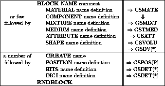
BLOCK, ENDBLOCK and CREATE are control operators because they affect the execution order: CREATE is executed as a jump to the requested BLOCK code and the return back when its ENDBLOCK is reached. All other are GEANT dedicated operators and are substituted by a call to one or a few GEANT routines via the AgSTAR interface .
Example 1:
Block VPDD  is the Vertex Position Detector assembly
     Material  Air
     Medium    Standard
     Attribute VPDD   Seen=0  colo=5
     Shape     TUBE   Rmin=vpdg_Rmin  Rmax=vpdg_Rmax,
                      Dz=vpdg_Length/2
     Rcurrent = vpdg_Rmin
     Do iLayer = 1,2
        Create   VRNG
        Position VRNG
        Rcurrent = Rcurrent + vpdl_DrLayer
     enddo
Endblock
The AgSTAR interface maintains GEANT tables of materials, mediums, volumes and rotation matrices. After checking that the requested name already exists in the corresponding table or having created a new table entry, the interface returns the entry number used in the GEANT routines.
The only mandatory operator inside a block is its SHAPE, others can be omitted.
In this case the volume properties are inherited from it's mother volume, and position definitions are assumed to be default (x=y=z=0, no rotation).
If needed, material, medium and attribute operators should be defined before the SHAPE operator.
2.2.2 More on SHAPE
The name argument of the SHAPE operator contains a name of any of the 16 legal GEANT shapes described in the manual. Keywords in the definition part are the names of parameters, used in the GEANT manual (section GEOM 050) to describe these shapes. The only exception are multiple z,Rmin and Rmax parameters of the PCON and PGON shapes, which should be supplied as vectors named Zi, Rmn and Rmx, defined in one of the following two forms: 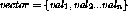
or 
where a vector stands for Zi, Rmn or Rmx,  are any Fortran expressions, and A is a Fortran array.
As the parameters are transmitted to the GSVOLU routine via the AgSTAR interface, they can be provided in any order or be inherited from the mother volume.
Example 2: the PCON specification from the GEANT manual (GEOM 050, figure 23) may look like:
    SHAPE PCON phi1=180 dphi=279 Nz=4 Zi={-400,-300,300,400},
               Rmn={50,50,50,50}      Rmx={250,100,100,250}
The GEANT divisions in the geant language are particular cases of the SHAPE operator. The actual division mechanism is automatically selected by the AgSTAR interface depending upon the parameters supplied.
Example 3: this will create divisions of a TUBE in  using GSDVN (GEOM 130):
   ....
     Shape  TUBE      Rmin=Rcurrent  Rmax=Rcurrent+vpdl_DrLayer,
                      Dz=Detector_length/2
     Create VSEC
   ....
*
Block VSEC  is one VPD sector with all stuff inside
     Shape  Division  Iaxis=2    Ndiv=vpdl_NumPMT,
                      C0=90+180/vpdl_NumPMT/iLayer
     Create ....
endblock
2.2.3 Inheritance rules
Unless defined explicitly, parameters of the MATERIAL, MIXTURE, MEDIUM, and SHAPE operators in a new block are inherited from the block creating it Normally this is also its mother volume. If no material or medium are defined in a new block at all, the are inherited from the mother block.
A MATERIAL or a MEDIUM operator without parameters can be used to refer to an already defined material (mixture) or medium.
Default materials, a priori known to the AgSTAR interface , are the 16 GEANT standart materials plus other materials described in the Particle Data Book [4].
The only tracking medium, known to the AgSTAR interface is the standart one, defined as following:
  Medium   Standard  Ifield=1 FieldM=20 TmaxFd=20 Epsil=0.01,
                     SteMax=10.0   DeeMax=-0.02   StMin=-0.01
A new GEANT medium is automatically introduced even without a MEDIUM operator, if the material in a block has been changed by a MATERIAL or MIXTURE operator.
2.3 Volume positioning
Unless defined explicitly, the parameters of a POSITION operator have the default values: x=y=z=0, KONLY='ONLY', unit rotation matrix.
If the volume being positioned has been defined with all parameters equal to zero, the GSPOSP routine will be called, otherwise the GSPOS is used. In case of the GSPOSP call, the actual parameters of the volume shape supplied in the POSITION operator still follow the inheritance rules for the SHAPE operator.
If a rotation should be defined when positioning a volume, it is possible to define it in several ways:
- Providing up to 6 parameters, describing a new orthogonal coordinate system (GEOM 200). The parameter names and their default values defining the unit matrix are
 ,
,

Only those parameters which are different from the default unit matrix should be given.
Example: The two copies of the VPDD block, mentioned in the example 1, are positioned in CAVE with
      Position VPDD in Cave  z=+vpdg_Position
      Position VPDD in Cave  z=-vpdg_Position   ThetaZ=180
where the second copy of the VPDD volume is a mirror reflection of the first one.
 or AlphaZ.
The ORT parameter can be combined with the other rotation definition taken into account that the axis substitution is done after all other rotations, i.e. rotation is defined in old axis.
For example to position a TRD1 trapesoid in a TUBS sector with a tilt angle alp relative to the tube axis, one can use POSITION IT somewhere AlphaZ=alp ORT=YZX
Rotation parameters are not inherited from one POSITION operator to another.
2.4 Volume naming mechanism
All volumes in GSTAR are referenced by their generic names, consisting of 4 upper-case letters . When the real dimensions of the same generic volume are variable, the supporting AgSTAR library provides an automatic and transparent mechanism which, for physically different volumes with the same generic name, generates nicknames used by GEANT, by changing last letters of the generic name into numbers or lower-case letters. These volumes with different nicknames are considered as instances of the same generic object. The original generic name is also kept in each instance together with its nickname.
The positioning of all volumes is done using their generic names, the latest generated instance of the object being actually used. When positioned in the same mother volume such instances will be distinguished also by their GEANT copy numbers. If a volume instance has been defined with all parameters equal to zero, it will be positioned by the AgSTAR interface using the GSPOSP routine, with the dimensions defined in the POSITION operator.
This mechanism provides a simple and effective way to automatically generate the unique path to each GEANT volume, needed for the HIT package, without additional user code.
2.5 Module header
The module header in AgSTAR is used to provide the Fortran declarations as well as the program maintenance information. It consists of the following geant declarations :
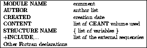
Note that:
- The first line should be the MODULE declaration. The order of other statements is irrelevant. The module name consists of a 4-letter STAR detector code plus the module type code (GEO, DIG etc). It is also used to identify module input and output data structures (GEANT hits and digits, parameter records in the DETM geometry database).
- The format of MODULE comment, author list and creation date is arbitrary, but their presence is mandatory.
- The CONTENT declaration should list all blocks used in the module.
- The STRUCTURE declaration groups together real variables or arrays , which are subject to potential change using KUIP datacards or should be accessible from external routines, for example at the reconstruction stage. Their usage is described in the next section.
Example:
     module   VPDDGEO  is the Vertex Position Detector of STAR
     Author   Z.Milosevich, P.Nevski
     Created  27 March 1996

     CONTENT   VPDD,VRNG,VSEC,VDET,VCNV,VRAD,VSUP,VPMT,VXST
     Structure VPDG { Version, Rmin, Rmax, Length, Position,
                      PMTradi, PMTwall, PMTleng,
                      EleLeng, ConvThk, RadiThk,
                      TubeThk, SuppThk, SuppDist }
     structure VPDL { Layer,   DrLayer, NumPMT   }

* external (GEANT and AGI) sequences
     +include,AGECOM,GCUNIT,GCONST

* Local variables
     Real      Rcurrent, Detector_Length
     Integer   iLayer
2.6 Data structure handling
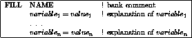
A group of logically linked variables, which are declared in a STRUCTURE operator, is defined using the FILL statement:
The whole collection of user's banks, created by FILL operators, is kept as a single tree DETM of structurally linked banks. It is saved after the program execution in the RZ data base (both the bank content and the relevant documentation) and can be used by reconstruction programs.
Note that:
- The structure name consists of 4 letters and is used as the ZEBRA bank name and as the prefix of its variables in the Fortran code.
- The order of assignments is irrelevant, but comments and explanations are mandatory.
- Other comment lines cannot be interleaved with FILL assignements.
 are Fortran expressions in case of a simple variable or a vector in the form
  for an array.
- When the FILL statement is executed by the AgSTAR interface, the data are saved as a bank in the DETM structure.
There may be two levels of data structures (banks) defined and used in a module: the structure name, defined by the first FILL operator, becomes the high level structure name. All structures with other names are considered as lower level structures associated to it.
Each of these structures may be a linear chain of similar banks, created by sequential FILL operators with the same name. They all are considered as instances of the same generic object, so at any moment only one selected copy of each structure is available. A typical usage of the high level structure is to provide different geometry versions of the same detector, the actual version been selected using the datacard input. Instances of the low level structures can be used to provide parameters for different components of the of the same detector.
Example:
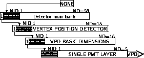
     FILL VPDG           ! VPD basic dimensions
        Version  = 1         ! geometry version
        Rmin     = 4         ! VPD inner radius
        Rmax     = 16        ! VPD outer radius
        Length   = 30        ! full VPD assembly length along the beam
        Position = 250       ! Z position of VPD along beam axis
        PMTwall  = 0.1       ! PMT wall thickness
        PMTradi  = 2.54      ! PMT and detector radius
        PMTLeng  = 8.0       ! PMT tube length
        EleLeng  = 15.0      ! electronics mount length
        ConvThk  = 0.635     ! Converter layer thickness
        RadiThk  = 0.635     ! Radiator layer thickness
        TubeThk  = 0.00      ! piece of beam pipe thickness (if needed)
        SuppThk  = 0.64      ! Support rings thickness
        SuppDist = 16        ! distance between supporting rings
*
     FILL VPDL           ! single PMT layer
        layer    = 1         ! layer number
        DrLayer  = 6         ! layer radial width
        NumPMT   = 8         ! number of PMT in layer
*
     FILL VPDL           ! single PMT layer
        layer    = 2         ! layer number
        DrLayer  = 6         ! layer radial width
        NumPMT   = 16        ! number of PMT in layer
     Endfill
Example: data structures produced by the previous example:
One can select the actual copy of the structure to be used by the program (an instance of the data structure) with the help of the USE statement :
USE NAME variable=value
Any variable from the corresponding structure can be used to select the current instance of the bank. The value may be any Fortran expression.
Example: USE VPDG version=1
USE VPDL layer=1
Once the top level bank is selected with the USE operator, the descendent lower level banks are selected only within the same branch. In geometry modules selected top level bank is re-linked at the first position of a possible linear chain, so that it always become default bank for any further selection. Also at that moment their content is changed by the standard datacard input.
Once selected with the USE operator, variables from the data structure can be referenced by the program in the form BankName_Variable. In this way they are easy to recognize among the other program variables (see first example).
This mechanism provides an easy and flexible way of the geometry versioning within each module.
3 CREATING GEANT HITS
In AgSTAR user does not need to write a detector specific routine to create GEANT hit structure and to fill it with a useful information. Instead, a geant statements with the HITS operator, called in a block describing a sensitive volume, is used to produce a relevant GEANT hit definitions and to steer their filling at the tracking time. This statement generates all necessary GEANT calls (see GSDET and GSDETH routines, HIT 100) with their parameters as follows:
- The set name is defined by the first 4 letters of the module name;
- The detector name is the name of the geant block ;
- Following the GSTAR standard, IDTYPE is taken as the STAR detector number;
- The name argument of the HITS operator, (hit address) is the name of the volume used to identify the hit, usually the sensitive detector itself. The AgSTAR interface finds the path to the selected volume using generic names of all higher level volumes and builds the NAMESV array. It also defines the number of branchings and the number of bits required at all levels (NBITSV array) to uniquely describe the path to each instance of the selected volume;
- For memory allocation defaults values of NHWI, NWDI = 1000 are used.
The definition part of the HITS operator contains a list of information quantities, measurements,
which should be saved in each GEANT hit, and their packing in one of the form  or
or 
For a measurement,  or bin are mandatory, option and limits are optional. At present the following variables are known as measurements to the AgSTAR interface (the track point means here the middle point of the track segment producing the hit in the sensitive volume):
- xx,yy,zz - track point coordinates in Master Reference System (MRS);
- x,y,z - local cartesian coordinates of the track point;
 - local cylindrical (or polar) coordinates of this point;
- Cx, Cy, Cz - local direction cosines of the track segment;
- Px,Py,Pz - components of the track momentum in MRS;
- Ct - cosine of the angle between the track segment and the radius pointing to its center;
- TDR - closest approach of the track segment to the local z-axis;
- STEP - the length of track segment producing the hit;
- SLENG - track length from the vertex;
- ELOS - the energy lost at this step;
- BIRK - registered energy loss, corrected by Birk's law (see PHYS 337);
- TOF - time of flight for this hit;
- ETOT - particle energy in the current point;
- LGAM -
 of the particle Lorentz factor;
 - ETA - pseudorapidity of the track point.
An integer number, following a measurement variable, is interpreted as  - the number
of bits for packing the variable values. 0 means that the value is a cumulative sum,
occupying a full computer word. Due to the GEANT limitation 0 can be used only in last elements of the HITS statement.
If a measurement variable is followed by a real number or an expression, it is interpreted as the packing bin size, and the number of bits, required for packing, will be calculated by the AgSTAR interface.
If the user does not provide the limits explicitly, min and/or max are determined by the AgSTAR interface using the volume dimensions. This works fine in local coordinates, but should be used with caution in global MRS coordinated.
Example: HITS VRAD xx:16:H(-25,25) yy:16:(-25,25) zz:32:(-1000,1000),
px:16:(-100,100) py:16:(-100,100) pz:16:(-100,100),
Slen:16:(0,1.e4) Tof:16:(0,1.e-6) Step:16:(0,100),
SHTN:16: Eloss:32:(0,1)
Possible measurement options are listed below. If an option is not mentioned, the alternative default solution is used. Most of the options acts on the whole list of measurements, except for option R.
- C - calorimeter type HITS, i.e. comulative values for all tracks are added together. By default comulative values are added for each KINE track separately.
- H - interprete the rest of the non-comulative hit elements as measured values rather than pseudo-volumes. By default any non-comulative hit elements are concidered as pseudo-volumes, is stored in the volume part of GEANT hits and used to distinguish between defferent comulative channels
- X - calculate local coordinates even if they are not required by the list of hit elements. They may be used in a user defined hit element.
- S - Single step option, i.e. a single hit will be produced for several sequential steps made by the same particle in a sensitive volume, until the particle exits it or a STEMAX limit is reached. By default a separate his is produce for each step performed by GEANT.
- R - bin rounding up to 2 decimal digits is done. Default is the exact value to fit the required bin or
 value.
3.1 Non-standard HIT elements
In a number of cases user may need in hits a specific value, unknown to the AgSTAR interface . There are two possibilities to provide such a value to AgSTAR interface :
- to hang a rotine YYYYHIT(pointer,hit) to be executed for any hit referencing a YYYY measurement.
- to hang a routine XXXXSTEP(pointer,hit) to be executed in a specific sensitive block XXXX using USER hit element. This is especially usefull when user wants to control and in certain cases to correct the normal values, calculated by the AgSTAR interface (i.e. instead of a linear track center approximation to use the parabolic one, like it is done in TPADSTEP routine of the TPCEGEO module).
Example:
So called shower track number is calculated for a SHTN element in a GSTAR specific routine SHTNHIT. It is used in most of the STAR tracking detectors to provide in their hits the secondary particle (i.e produced by GEANT) track number (see the previous example of the VPD hits).
These subroutines should be described as EXTERNAL in the module header. Their first integer input argument pointer is the address of the hit descriptor array (10 words, real) in the GCBANK memory and they should return in the second real argument hit the measurement.
4 DIGITISATION
The detector digitisation, i.e. simulation of the response of individual elements of a given detector after tracking of a compete event, can be done in a separate geant
Such digitisation module should have the header and the data handling part similar to a geometry module, but instead of blocks, describing detector geometry, it describes how a specific detector response in each separate element is produced, taken into account multiple hit overlap, noises, thresholds etc.
When a user reads measured quantities from hits, standard GEANT user's facilities, like the transformation from local coordinates to MRS, are automatically available, thus allowing to use significantly more dense hit formats.
4.1 Collecting all hits in a detector element
The AgSTAR interface provieds 2 integer functions (AgFHIT0, AgFHIT1) which perform the hit access. Their execution and the print verbosity are controlled by the datacards in a way described later. If the operation was successful, the functions return the OK flag (0 value).
To select a hit set to be analyzed, a AgFHIT0(Cset,Cdet) function should be called, where Cset and Cdet are 4-letter names of an STAR system and its sensitive detector. The function returns OK if the selected set contains hits, and the digitisation of this systemwas allowed by control cards, otherwise the digitisation should be abandoned.
After the initialization call is successfully done, the AgSTAR interface is ready to provide sequentially all hits in each detector element by performing the AGFHIT1 (IH, ITRA, NUMBV, HITS) function.
Here the output arguments of the function are :
- abs(IH) - the sequential hit number in the current detector element. A negative IH is used to signal the last hit in the detector element.
- NUMBV - an integer array, that contains on output the list of volume copy numbers which identify the path to this detector element. This array may be passed to the AGFPATH(NUMBV) routine to re-install all GEANT transformation matrices to allow local to global coordinate conversion.
- HITS - a real array which will contains the measurements assigned by the HITS operator to this hit to this hit.
- abs(ITRA) - the track number having produced this hit. The negative ITRA is used to signal that other particles also contributed to this detector element.
The function itself returns OK until all hits in the selected set are used.
In this way in the digitization routine the user does not need neither to introduce arrays to accumulate the information from different detector elements in parallel, nor even to know the full number of the detector elements. Moreover, if a user needs to know the space position of a hit, he can simply use the GEANT routine GDTOM to translate a point in the current detector element to the Master Reference System, after the content of the necessary common blocks is restored by the AGFPATH routine.
Below is an example how all hits in the TPC can be read and analized:
     Module  TPCEDIG is the TPC digitization
     Author  P.Nevski
     Created on sunday afternoon
*
     integer AgFHIT0,AgFHIT1,i,ih,itra,NumBV(5)
     real    hits(15),Esum
*
     check AgFHIT0('TPCE','TPAD') == ok
     Do While (AgFHIT1(ih,itra,NumBV,hits) == ok)
        If (abs(IH)==1) then
*          we are getting a new padraw
           Esum=0
           CALL AGFPATH(NumBV)
        endif
*
        Esum=Esum+abs(HITS(11))
*
        If (IH<=0) then
*          this is the last hit in the padraw
           print *,' Padrow number ',(NumBV(i),i=1,3),
                   ' energy sum is ',Esum
        endif
     enddo
     END
5 INTERACTIVE COMMANDS
The AgSTAR interface linked with an iteractive GEANT provides a unique possibility to study, modify and to debug the description of the STAR geometry. A special macro-command, geom.kumac , compiles, dinamically links and executes any external routine, in particular geometry or digitization modules.
In particular one can perform the following operations with a single geometry module or with a complete STAR detector:
- GDROP - clear ZEBRA memory by droping all previously created banks.
- EXEC GEOM module-name - to compile, link and execute a module written in a separate file. The name of the file should be the same as the module name with the extension .g .
- DEBUG ON - to switch on the debugging mode with the level of printout defined by the module PRIN flag (see below). Most of the parameters of the created volumes, materials, media and rotation matrices can be printed without modifying a single line of the code.
- RZ/FILE 1 STAR.geom I - to read in a geometry file of the STAR detector from the current directory.
- DRAW ... or DCUT ... - to draw different views of the selected system or its parts using GEANT graphics. In the debug mode (after DEBUG ON command) an isometric view of the system is drawn automatically.
- DTREE ... - to draw the logical tree of the GEANT volumes with their generated nicknames and dimensions.
- DISP detm detm.rz - to survey the tree of the created data structures, to navigate through them, to see the actual content of each created bank with its description, extracted from the module by the AgSTAR interface.
- GDUMP path option - to dump the content of all or of a selected part of detector description banks from the DETM geometry data base. The dump may be written in a file (option F), as a plain text, SGML(S) or HTMP(H) formated text, or as set of numbers to be read in by another program (option C)
- GKINE Npart Ptype Pmin Pmax Ymin Ymax PhiMin PhiMax to define parameters of simulated particles
For more details see the XINT section of the GEANT3 manual and use the HELP facility of the interactive GSTAR
6 DATACARD CONTROL
6.1 Program control
Different functions of individual modules are controled by there control flags. These flags for any module are accessed using MODE detacard

These flags are used to control the geometry building (GEOM), hit saving in sensitive detector (SIMU), switching on/off of the magnetic field (MFLD), the print verbosity (PRIN), graphics details (GRAP).
6.2 Print control
In general the action of the resulting print level  is defined by the following strategy:
- 0 - no printout at all (same for L negative);
- 1 - minimal printout (not more than once per event);
- 2 - still reasonable amount of prints (up to 10 lines per event);
- 3 - you can tolerate it for a dozen events;
- 4 and more - debugging to find a problem.
Some particular cases for different stages are explained below.
6.2.1 GEOM - Geometry building stage
The print level decreases by one each time the program makes a jump into a next level block. So with small L you will get only general detector dimension, and with higher L you will get parameters of smaller detector pieces.
6.2.2 SIMU - Simulation stage
The printout, tracing particles, is done by the GEANT routine GDEBUG. This routines operates under the control of DEBUG and ISWIT data cards (see section BASE 400) and may produce a very abundant printout.
In addition, the AgSTAR interface provides a possibility to tracing particles only in selected STAR detector systems. A detector MODE XXXX DEBU D data card is used to limit the maximal volume insertion level, where a call to GDEBUG is done. So with D=1 one will get the tracing only the system mother volume, and with higher D from its internal volumes. The total number of volume levels, where the tracing is done, is defined by the detector print level.
6.3 Parameter input
The content of a data structure, defined in any module, can be modified by a DETP KUIP card. To modify a variable, user has to provide
- the name of the detector,
- the name of the desired bank,
- the value of the ``use'' selector of the desired bank,
- then names and new values of variables in the selected bank.
All modification for the same detector should be done on the same *DETP datacard, which can be continued an several lines following the KUIP rules (underscore as continuation simbol). Example. To modify the ``number of PMT in layer'' number two in the example on page 8, one can use the following datacard: DETP VPDD VPDL= 2 numPMT= 17
Note that identificators are case unsensitive, but values should be separated by blanks.
7 DOCUMENTATION AND DATABASE SUPPORT
As it has been already mentioned, when the FILL statement is executed by the AgSTAR interface,
the data are saved as a bank in the DETM structure []. At the same time the AgSTAR
interface creates the appropriate documentation banks for DZDOC package [2].
For each bank in the DETM structure the documentation banks contain the creation date, authorship information, the variable names and comments as well as the full information on the bank relationship.
All this information is maintained in a RZ-file detm.rz which can be analysed by the DZDOC package. Running its interactive version DZEDIT, users can get the full information on the created banks as well as to print a hardcopy of the current STAR input data structure description. As the documentation RZ-file is updated automatically each time the program has been changed, this description is always up-todate.
In a future it will become possible to get with the USE operator not only versions of banks, defined directly in the module, but also to read them from the STAR geometry data base, supported centrally.
References
- 1 GEANT - Detector Description and Simulation Tool. CERN Program W5013. Geneva, 1994.
- 2 DZDOC - Bank documentation tools. In ZEBRA, CERN Program Q100/Q101. Geneva, 1993.
- 3 HEPDB - Database Management Package. CERN Program Q180, Geneva, 1993.
- 4 Particle physics booklet, 1994, AIP, p.224
- Printer-friendly version
- Login or register to post comments