Last Mapping of EPD for 2023, DSMs, etc.
Executive Summary
West Side was installed. The dark current looks similar to when it was removed. We took a spare QT32B connector from the EPD cabinet (looks like there was one more, plus 2 QT32C connectors) and connected the 5 "bad" tiles from earlier. Mike needs to send values to Tristan for upload.
EQ4: Moved BOC board to far left slot as instructed. Removed DSM label. Moved 1 QTC adaptor board from EQ2 up to EQ4. No ribbon cable moved.
EQ2: Removed all the QTB connections to the back plane. Moved all the QTC Adaptor cards to their proper positions. Currently everything is connected the East. There is one East QTC ribbon cable that is not attached.
EQ1: Removed all QTB connections. 2 West QTC Ribbon Cables are taped in, ready to be connected. 3 Extra West Connections are taped in.
EQ3: Removed all QTB connections. 2 East and 2 West QTC Ribbon cables are taped in, ready to be connected.
What I think needs to happen:
EQ3: Plug in the connectors that are there
EQ1: Plug in 2xW connectors that are there.
Move 3 extra West connections to next rack with EQ2/EQ4 (2 goto EQ2, 1 goes to EQ4)
Extend loose QTC East connector in EQ2/EQ4 rack so it can reach EQ4
Move 2 east connectors from EQ2 to EQ1
Details
Prashanth, Tristan and Bill S. installed the West EPD disk and fibers Wednesday March 22nd. Mike and Tristan installed the West SiPMs and light tighted the West side. Currently the East side is scheduled for April 11.
Light Tighting
The dark current comparison from the end of last run, to now on the West side can be found below.
.png)
Figure 1: Dark current at Run 22 bias voltage settings comparing the end of last run (black) to the install (red).
.png)
Figure 2: Dark current at Run 22 bias voltage settings comparing the end of last run (red) to the beginning of last run (black).
The data is recorded by pressing "Save As" on the GUI. The comparison macro can be found at: drupal.star.bnl.gov/STAR/system/files/CompareDark_0.txt
The two data files are: drupal.star.bnl.gov/STAR/system/files/EPD2023_2_24_13_27.txt and drupal.star.bnl.gov/STAR/system/files/EPD2022_3_18_10_33.txt
Mapping
Next, we wanted to fix the last few channels that were mismapped from last time. The details from our earlier attempt can be found at: drupal.star.bnl.gov/STAR/blog/rjreed/Mapping-EPD-2172023 with the key aspect being the pdf (drupal.star.bnl.gov/STAR/system/files/EPDMapping02172023_0.pdf ) and the mismatches, which are:
MISMATCH!!! ew/pp/tt = -1/1/16 Should be EQ4 BD4 (i.e. 3rd board) CH 16
MISMATCH!!! ew/pp/tt = 1/2/4 Should be EQ2 BD10 CH10 Dead?
MISMATCH!!! ew/pp/tt = 1/2/14 Should be EQ2 BD14 CH02 Dead?
MISMATCH!!! ew/pp/tt = 1/3/13 Should be EQ2 BD14 Ch07
MISMATCH!!! ew/pp/tt = 1/6/1 Should be EQ3 BD8 Ch17 Dead?
All were properly mapped when we checked the connections. We checked some fraction and it seems that signal was coming out of the diffRx - Mike has the details for this. We then added another QT32B connector to EQ3 Bd 6 Ch 8-12 (I believe). These need to be added to the data base and the mapping needs to be checked again.
Checking QTC->DSM connections
Some details from Eleanor can be found at: drupal.star.bnl.gov/STAR/blog/rjreed/Checking-EPD-QTC-DSM
The crate configuration is:
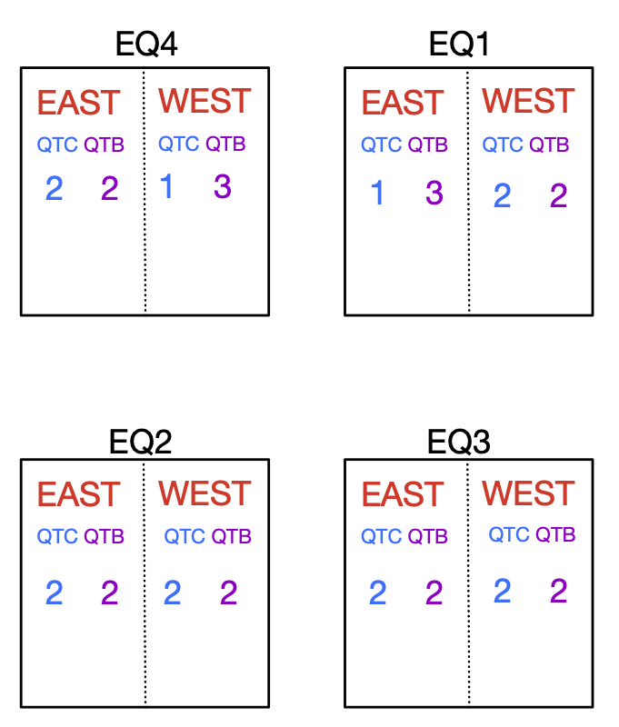
Figure 3: The current crate configuration as viewed by a person standing in front of them. The crates are now all divided with the East on the left and the west on the right. Each crate has 8 QT boards, 4 East and 4 West.
Previously, EQ1 was West, EQ2 was East and EQ3 was divided East/West. They also had 11,11,10 boards in them respectively.
The old arrangements are:

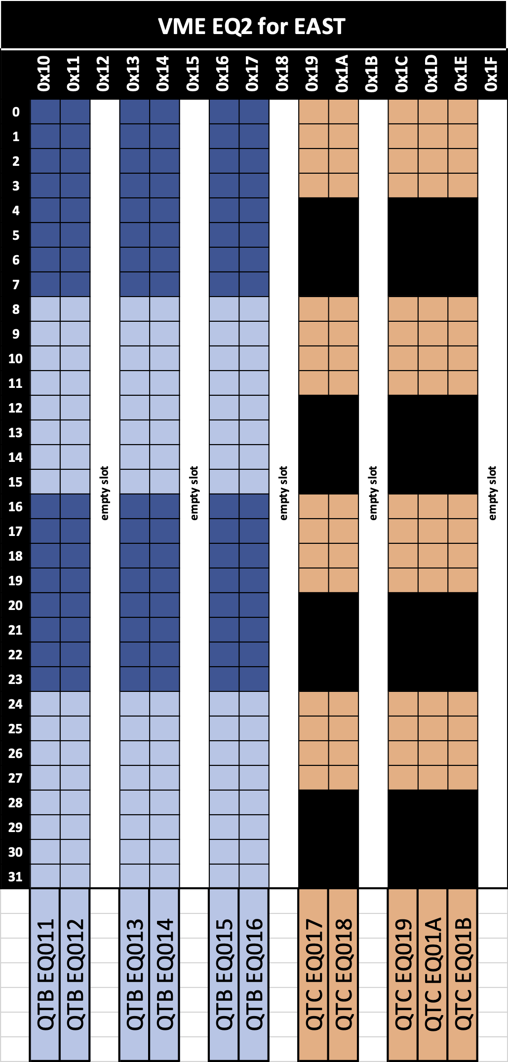

Figure 4: Old EQ arrangements.
.png)
Figure 5: New EQ Arrangement.
Actions...
EQ4: Moved BOC board to far left slot as instructed. Removed DSM label. Moved 1 QTC adaptor board from EQ2 up to EQ4. No ribbon cable moved.
EQ2: Removed all the QTB connections to the back plane. Moved all the QTC Adaptor cards to their proper positions. Currently everything is connected the East. There is one East QTC ribbon cable that is not attached.
EQ1: Removed all QTB connections. 2 West QTC Ribbon Cables are taped in, ready to be connected. 3 Extra West Connections are taped in.
EQ3: Removed all QTB connections. 2 East and 2 West QTC Ribbon cables are taped in, ready to be connected.
What I think needs to happen:
EQ3: Plug in the connectors that are there
EQ1: Plug in 2xW connectors that are there.
Move 3 extra West connections to next rack with EQ2/EQ4 (2 goto EQ2, 1 goes to EQ4)
Extend loose QTC East connector in EQ2/EQ4 rack so it can reach EQ4
Move 2 east connectors from EQ2 to EQ1
- rjreed's blog
- Login or register to post comments