2009
Year 2009 posts
01 Jan
January 2009 posts
2009.01.08 Away side jet pt vs. photon pt
Ilya Selyuzhenkov January 08, 2009
Data sets
- pp2006 - STAR 2006 pp longitudinal data (~ 3.164 pb^1)
Trigger: eemc-http-mb-L2gamma [id:137641] - gamma-jet[gamma-filtered] - data-driven Prompt Photon [p6410EemcGammaFilter] events.
Partonic pt range 2-25 GeV. - QCD jets[gamma-filtered] - data-driven QCD [p6410EemcGammaFilter] events.
Partonic pt range 2-25 GeV.
Cuts applied
- Di-jet events
- Require to reconstruct photon momentum (no gamma-jet isolation cuts)
- Gamma pt > 7GeV
- L2gamma emulation in Monte-Carlo
- L2gamma triggered pp2006 events
Comments
(concentrated on pre-shower1>0 case
which has better statistics for QCD Monte-Carlo):
- Fig.1, lower plots
Vertex z distributions from QCD MC and pp2006 data are different in the negative region - Fig.2, lower plots
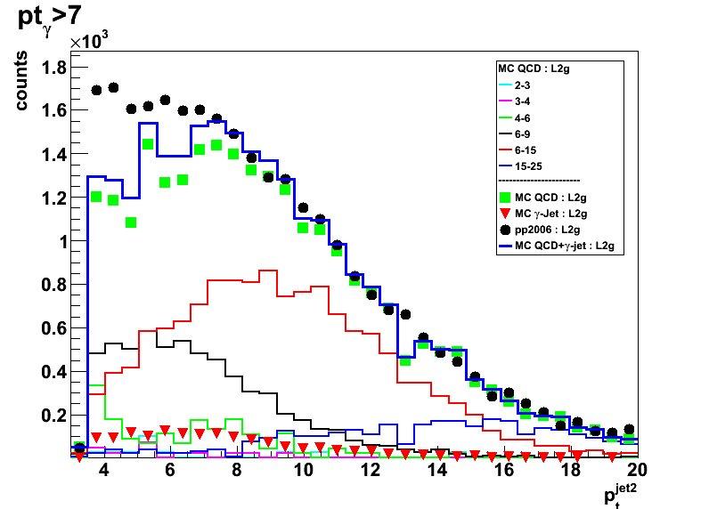
For the away side jet pt < 8GeV region
QCD Monte-Carlo underestimates the data. - Fig.4, lower plots
gamma-jet pt asymmetry plot shows
that in QCD MC photon and jet pt's are better correlated than in the data - Fig.5, lower plots
Most of the differences between QCD MC and pp2006 data for pre-shower1>0 case
are probably from the lower gamma and jet pt region
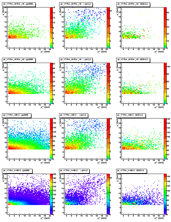
Figures
Figure 1: Vertex z distribution
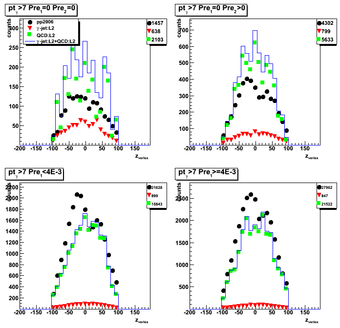
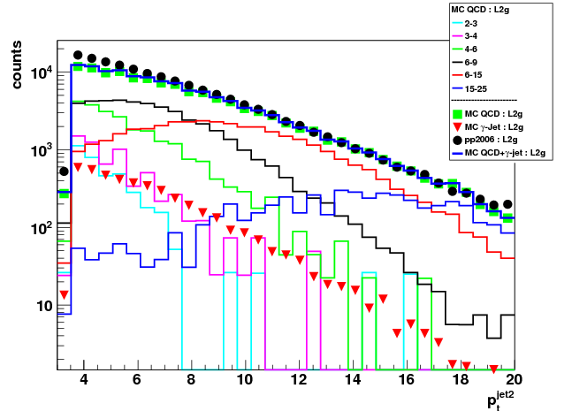
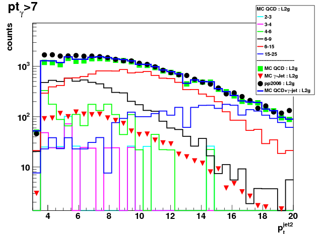
Figure 2: Away side jet pt
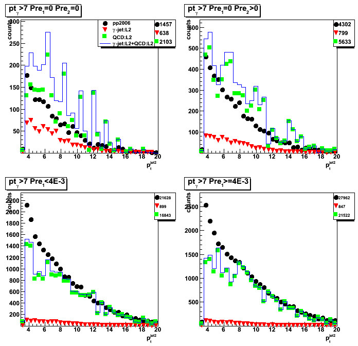
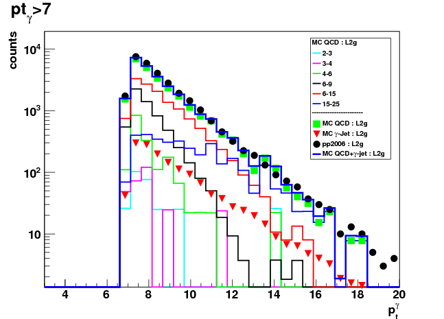
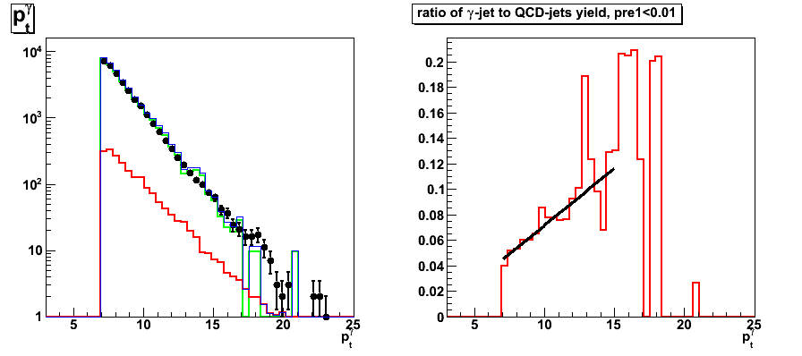
Figure 3: Photon pt
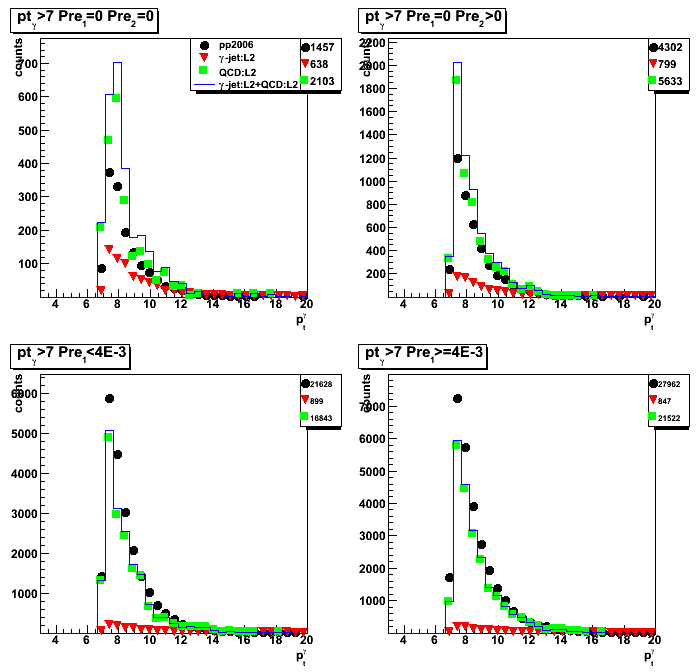
Figure 4: gamma-jet pt asymmetry: (pt_gamma - pt_jet)/pt_gamma
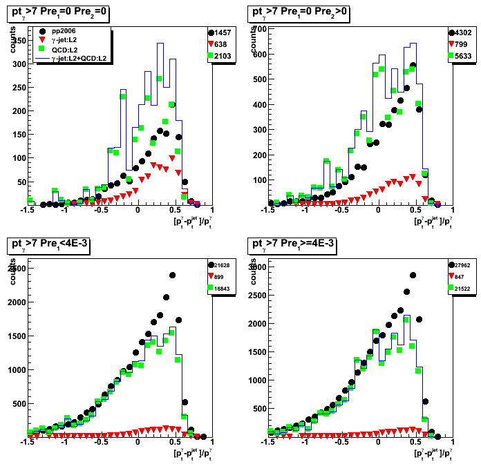
Figure 5: gamma pt vs. away side jet pt
1st column: triggered pp2006 data
2nd column: gamma-jet MC (l2gamma trigger on)
3rd column: QCD background MC (l2gamma trigger on)
2009.01.20 Away side jet pt vs. photon pt: more stats for QCD pt_parton 9-15GeV
Ilya Selyuzhenkov January 20, 2009
Note:
this is an update with 10x more statitstics for QCD 9-15GeV parton pt bin.
See this post for old results.
Data sets
- pp2006 - STAR 2006 pp longitudinal data (~ 3.164 pb^1)
Trigger: eemc-http-mb-L2gamma [id:137641] - gamma-jet[gamma-filtered] - data-driven Prompt Photon [p6410EemcGammaFilter] events.
Partonic pt range 2-25 GeV. - QCD jets[gamma-filtered] - data-driven QCD [p6410EemcGammaFilter] events.
Partonic pt range 2-25 GeV.
Cuts applied
- Di-jet events
- Require to reconstruct photon momentum (no gamma-jet isolation cuts)
- Gamma pt > 7GeV
- L2gamma emulation in Monte-Carlo
- L2gamma triggered pp2006 events
Comments
- Vertex z distributions from QCD MC and pp2006 data
are different in the negative region (see Fig.1) - pp2006 data to Monte-Carlo ratio
does not depends on reconstructed photon pt,
but it has some vertex z dependence
(see data to MC ratio in Fig.6 for pre-shower1 > 4MeV case)
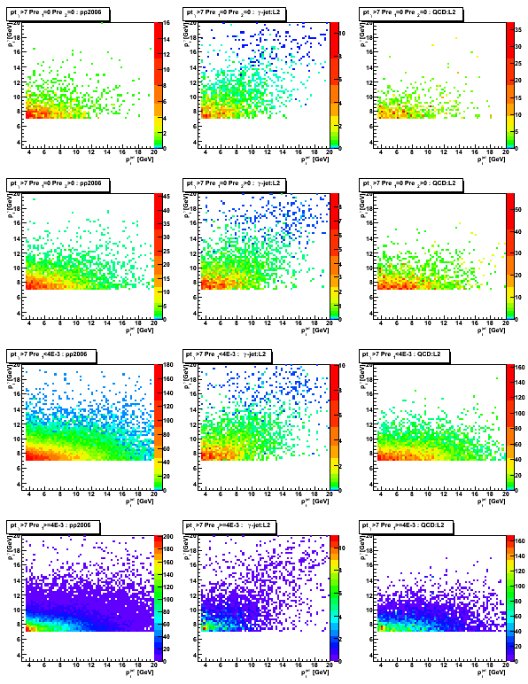
Figures
Figure 1: Vertex z distribution

Figure 2: Away side jet pt

Figure 3: Photon pt

Figure 4: gamma-jet pt asymmetry: (pt_gamma - pt_jet)/pt_gamma

Figure 5: gamma pt vs. away side jet pt
1st column: triggered pp2006 data
2nd column: gamma-jet MC (l2gamma trigger on)
3rd column: QCD background MC (l2gamma trigger on)
Data to Monte_Carlo normalization
Figure 6: pp2006 data to Monte -Carlo sum [QCD + gamma-jet] ratio
for pre-shower1>4MeV (most of statistics)
Left: data to MC ratio vs. reconstructed gamma pt.
Solid line shows constant line fit (p0 ~ 1.3)
Right: data to MC ratio vs. reconstructed vertex position

2009.01.27 gamma and jet pt plots with detector |eta|_jet < 0.8, pt_jet > 7
Ilya Selyuzhenkov January 27, 2009
Data sets
- pp2006 - STAR 2006 pp longitudinal data (~ 3.164 pb^1)
Trigger: eemc-http-mb-L2gamma [id:137641] - gamma-jet[gamma-filtered] - data-driven Prompt Photon [p6410EemcGammaFilter] events.
Partonic pt range 2-25 GeV. - QCD jets[gamma-filtered] - data-driven QCD [p6410EemcGammaFilter] events.
Partonic pt range 2-25 GeV.
Cuts applied
- Di-jet events
- Require to reconstruct photon momentum (no gamma-jet isolation cuts)
- jet pt > 7GeV
- Gamma pt > 7GeV or no pt cuts
- L2gamma emulation in Monte-Carlo
- L2gamma triggered pp2006 events
- cos (phi_jet - phi_gamma) < -0.8
- detector |eta_jet|< 0.8
- |v_z| < 100
Figures
All figures:
- All pre-shower conditions combined, pre1<10MeV
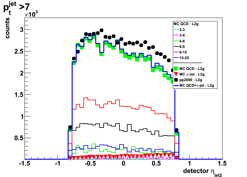
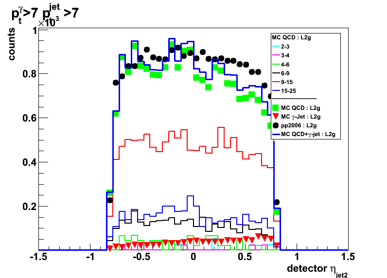
- Left plots: no gamma pt cut
Right plots: pt_gamma >7GeV - Thick blue line shows MC sum: QCD + gamma-jet
- Thin solid color lines shows distributions from various partonic pt bins for QCD MC
See figures legend for color coding
Figure 1: Vertex z distribution
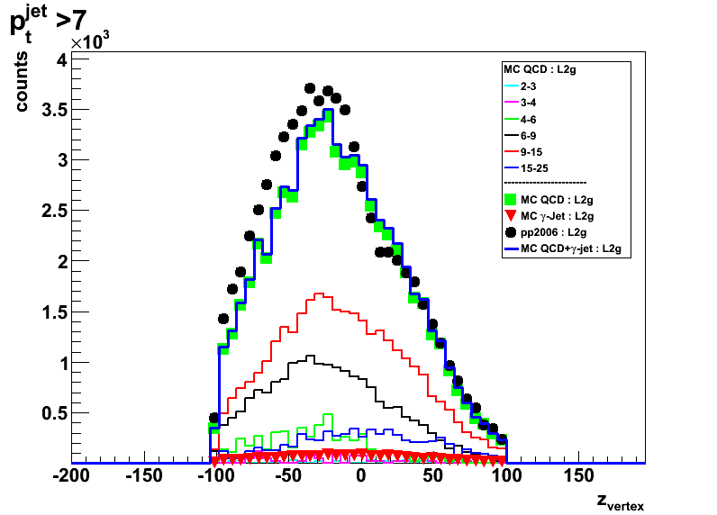
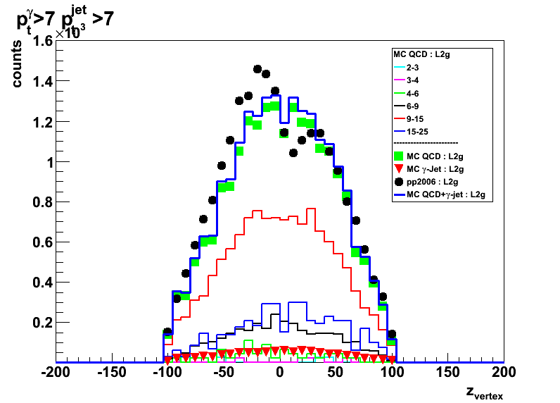
Figure 2: Photon eta
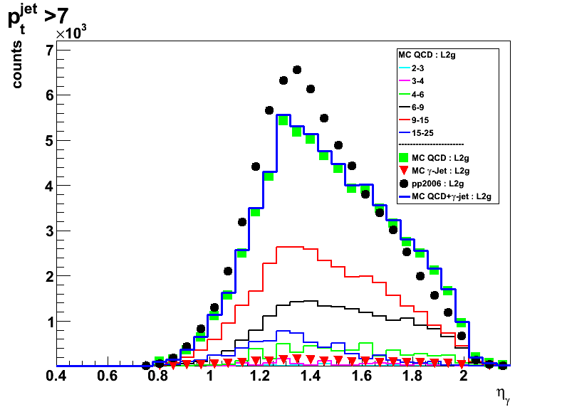
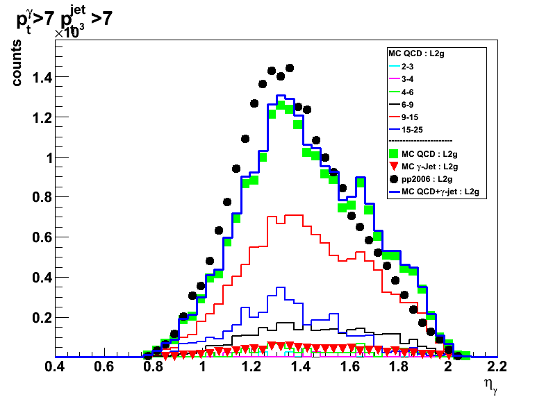
Figure 3: Away side jet eta

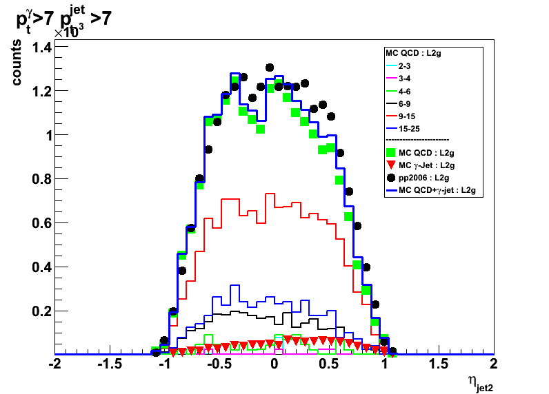
Figure 4:Photon pt
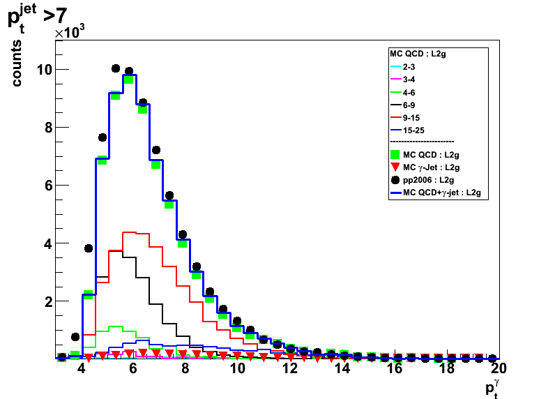

Figure 5: Away side jet pt
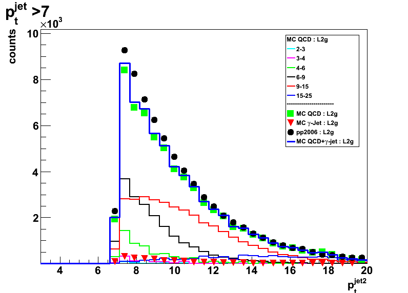
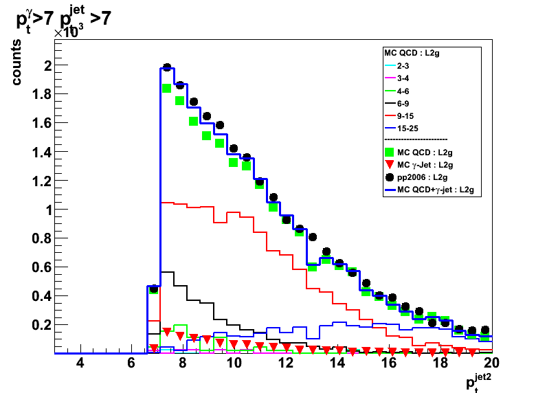
Figure 6: Away side jet detector eta
2009.01.27 gamma and jet pt plots with |eta|_jet < 0.7
Ilya Selyuzhenkov January 27, 2009
Data sets
- pp2006 - STAR 2006 pp longitudinal data (~ 3.164 pb^1)
Trigger: eemc-http-mb-L2gamma [id:137641] - gamma-jet[gamma-filtered] - data-driven Prompt Photon [p6410EemcGammaFilter] events.
Partonic pt range 2-25 GeV. - QCD jets[gamma-filtered] - data-driven QCD [p6410EemcGammaFilter] events.
Partonic pt range 2-25 GeV.
Cuts applied
- Di-jet events
- Require to reconstruct photon momentum (no gamma-jet isolation cuts)
- Gamma pt > 7GeV or no pt cuts
- L2gamma emulation in Monte-Carlo
- L2gamma triggered pp2006 events
- cos (phi_jet - phi_gamma) < -0.8
- |eta_jet|< 0.7
- |v_z| < 100
Figures
All figures:
- All pre-shower conditions combined, pre1<10MeV
- Left plots: no gamma pt cut
Right plots: pt_gamma >7GeV - Thick blue line shows MC sum: QCD + gamma-jet
- Thin solid color lines shows distributions from various partonic pt bins for QCD MC
See figures legend for color coding
Figure 1: Vertex z distribution
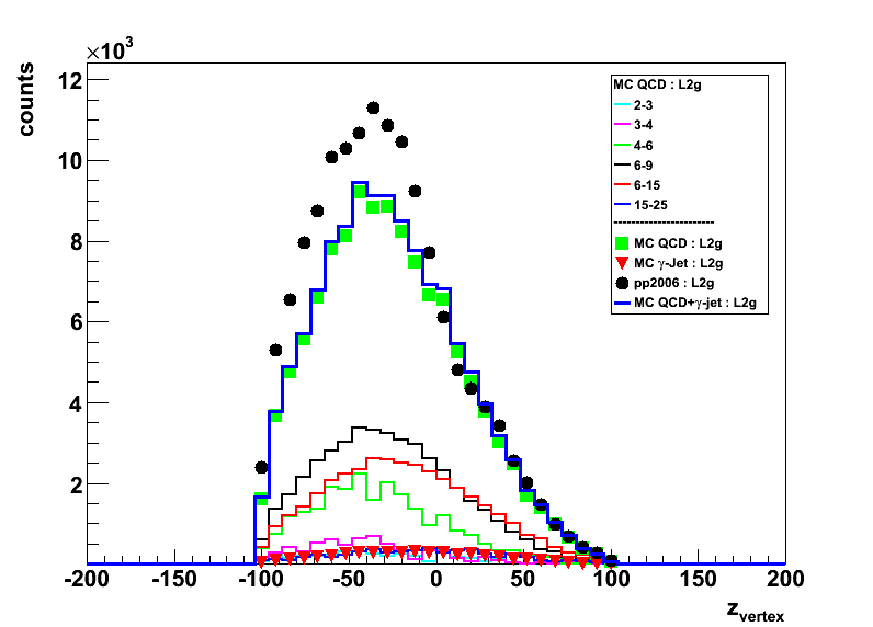
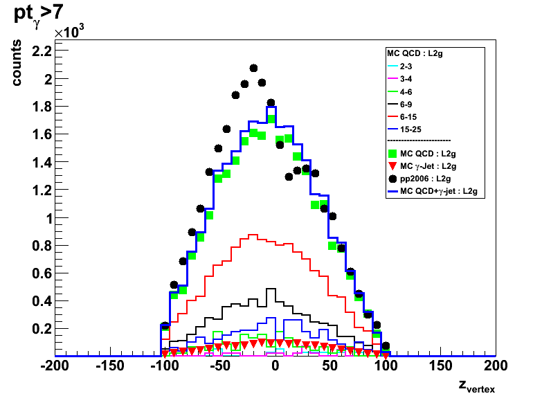
Figure 2: Photon eta
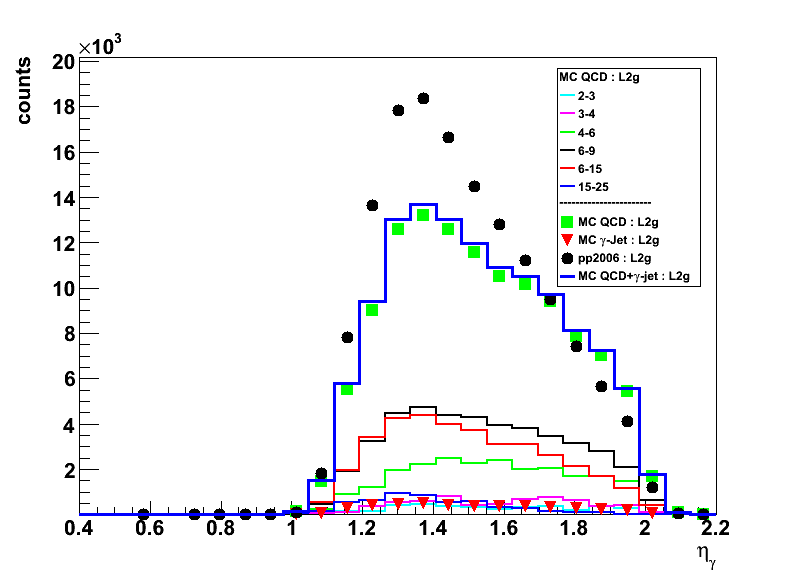
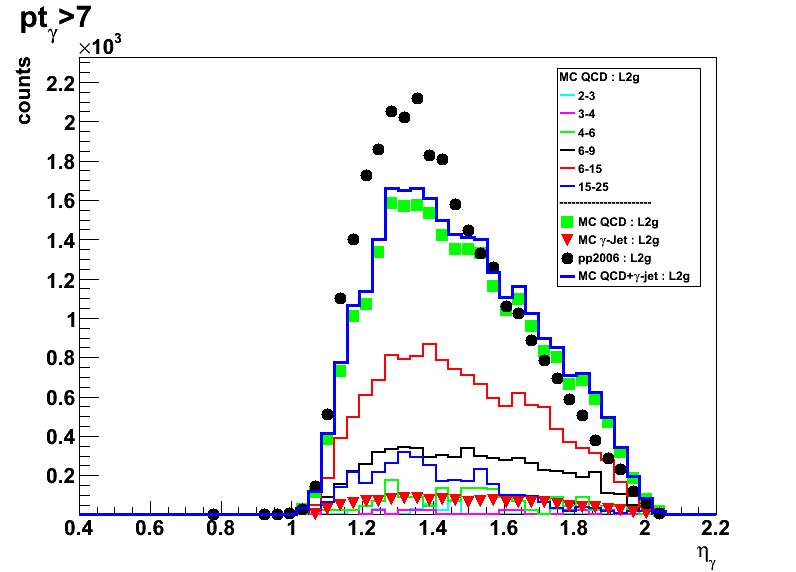
Figure 3: Away side jet eta
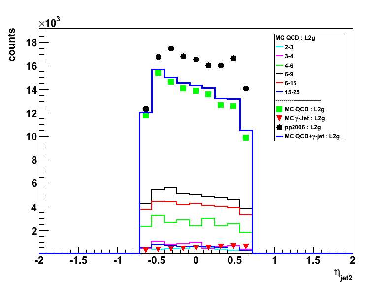
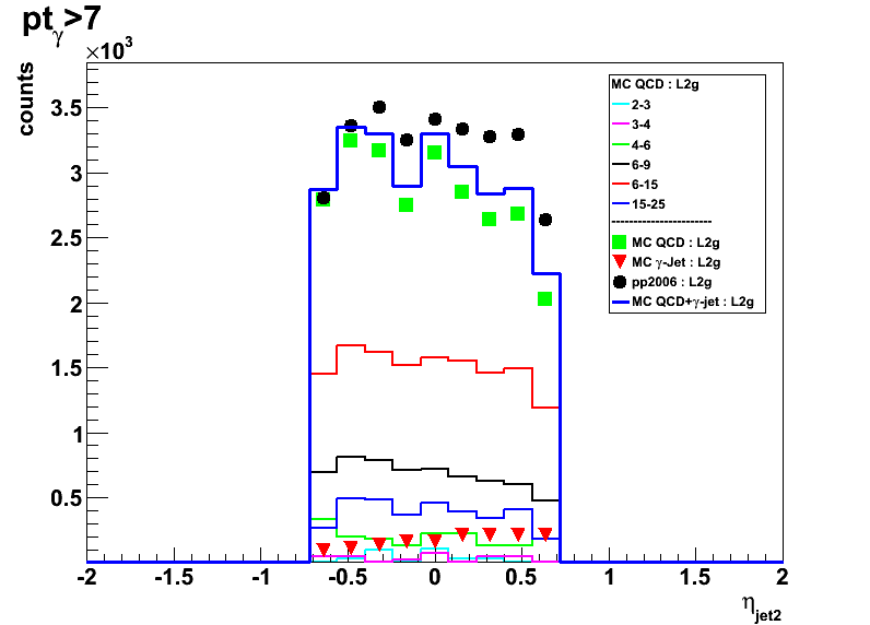
Figure 4:Photon pt

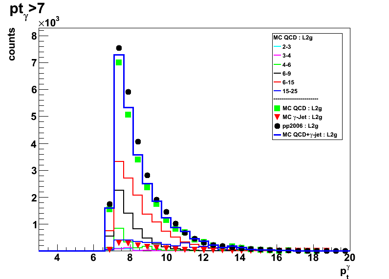
Same as in Fig.4 on a log scale: no gamma pt cut and pt>7GeV
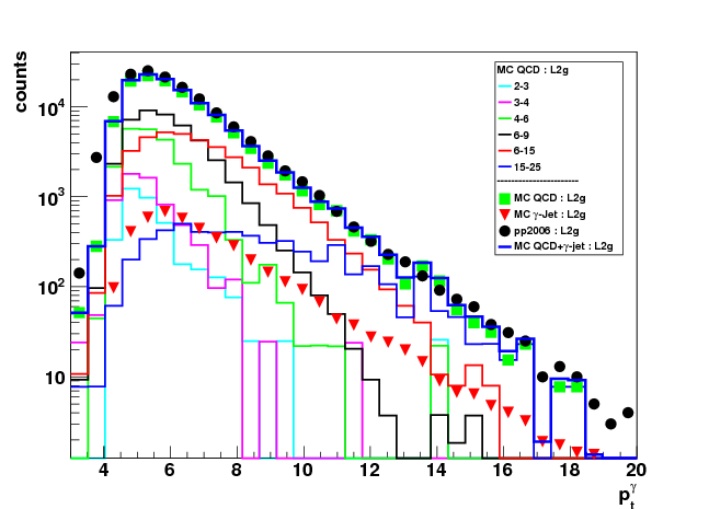
Figure 5: Away side jet pt

Same as in Fig.5 on a log scale: no gamma pt cut and pt>7GeV
02 Feb
February 2009 posts
2009.02.02 No pre-shower cuts, Normalization fudge factor 1.24
Ilya Selyuzhenkov February 02, 2009
Data sets
- pp2006 - STAR 2006 pp longitudinal data (~ 3.164 pb^1)
Trigger: eemc-http-mb-L2gamma [id:137641] - gamma-jet[gamma-filtered] - data-driven Prompt Photon [p6410EemcGammaFilter] events.
Partonic pt range 2-25 GeV. - QCD jets[gamma-filtered] - data-driven QCD [p6410EemcGammaFilter] events.
Partonic pt range 2-25 GeV.
Cuts applied
- Di-jet events
- Require to reconstruct photon momentum (no gamma-jet isolation cuts)
- Gamma pt > 7GeV
- L2gamma emulation in Monte-Carlo
- L2gamma triggered pp2006 events
- cos (phi_jet - phi_gamma) < -0.8
- detector |eta_jet|< 0.8
- |v_z| < 100
Figures
All figures:
- All pre-shower conditions combined, No pre-shower cuts
- Thick blue line shows MC sum: QCD + gamma-jet
- Black solid circles: pp2006 data
- Monte-Carlo results first scaled to 3.164 pb^-1 according to Pythia luminosity
and then an additional fudge factor of 1.24 has been applied.
Fudge factor is defined as the yields ratio from data to scaled with Pythia luminosity Monte-Carlo
for pt_jet>7GeV and pt_gamma>7 candidates
Figure 1: Vertex z distribution with pt_jet>7 cut (left) and without pt_jet cut (rigth)
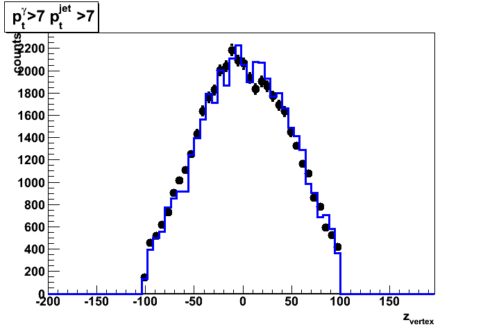
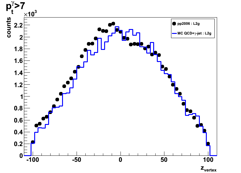
Figure 2: Photon (left) and away side jet (right) pt
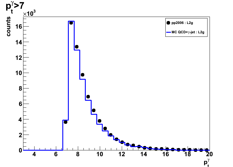
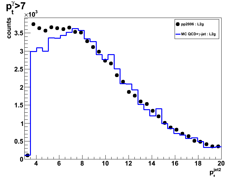
Figure 3: Photon detector eta (left) and corrected for vertex eta (right)
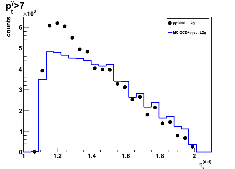
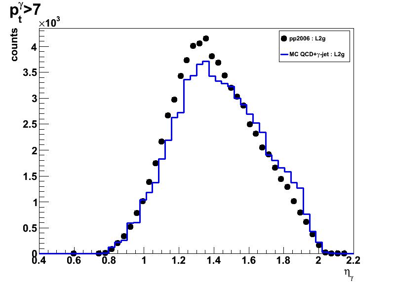
Figure 4: Away side jet detector eta (left) and corrected for vertex eta (right)
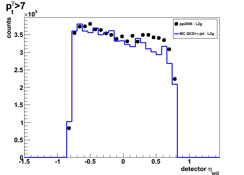

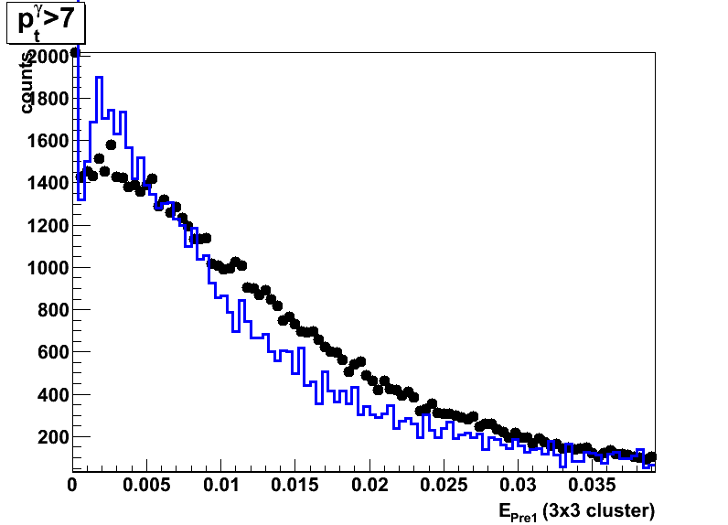
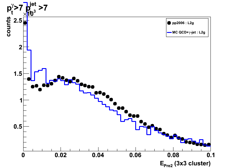
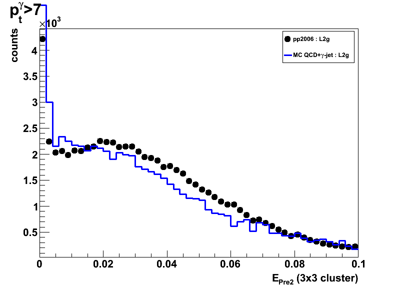
Figure 5: Preshower 1 (left) and Pre-shower2 (right) energy

2009.02.03 No pre-shower cuts, pt_jet >7 vs. No pt_jet cuts
Ilya Selyuzhenkov February 03, 2009
Data sets
- pp2006 - STAR 2006 pp longitudinal data (~ 3.164 pb^1)
Trigger: eemc-http-mb-L2gamma [id:137641] - gamma-jet[gamma-filtered] - data-driven Prompt Photon [p6410EemcGammaFilter] events.
Partonic pt range 2-25 GeV. - QCD jets[gamma-filtered] - data-driven QCD [p6410EemcGammaFilter] events.
Partonic pt range 2-25 GeV.
Cuts applied
- Di-jet events
- Require to reconstruct photon momentum (no gamma-jet isolation cuts)
- Gamma pt > 7GeV
- L2gamma emulation in Monte-Carlo
- L2gamma triggered pp2006 events
- cos (phi_jet - phi_gamma) < -0.8
- detector |eta_jet|< 0.8
- |v_z| < 100
Figures
Each figure has:
- All pre-shower conditions combined, No pre-shower cuts
- Thick blue line shows MC sum: QCD + gamma-jet
- Black solid circles shows pp2006 data
- Left plots: pt_jet>7GeV
Right plots: no cuts on pt_jet - Monte-Carlo results for QCD and gamma-jet samples are first
scaled to 3.164 pb^-1 according to Pythia luminosity,
added together, and then an additional fudge factor of 1.24 applied.
Fudge factor is defined as pp2006 to Monte-Carlo sum ratio
for pt_jet>7GeV and pt_gamma>7 candidates
Figure 1: Vertex z distribution
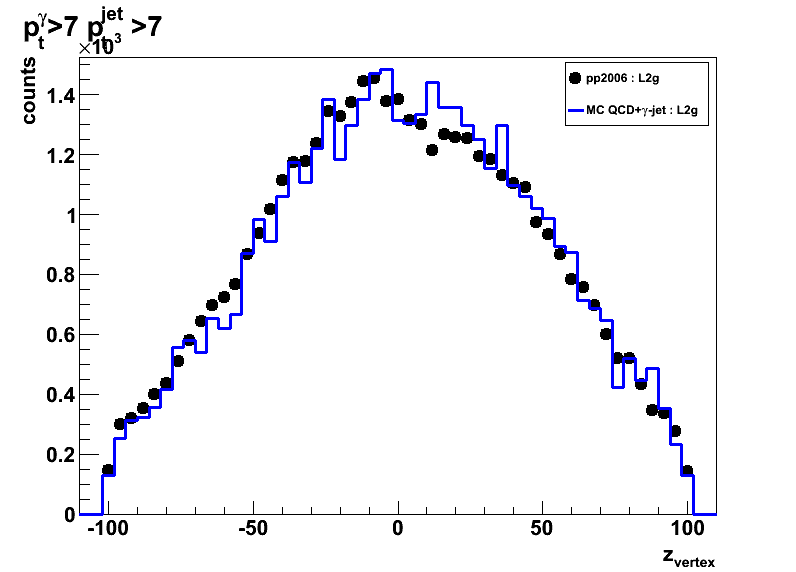

Figure 2: Photon detector eta
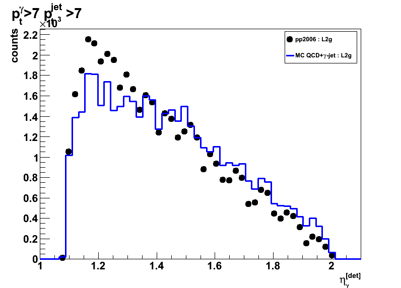

Figure 3: Corrected for vetrex photon eta


Figure 4: Away side jet detector eta
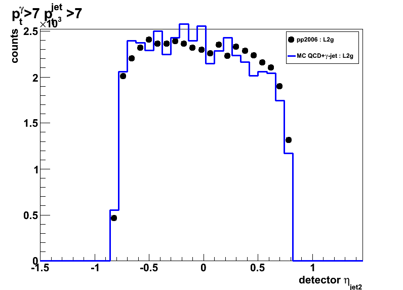

Figure 5: Corrected for vetrex away side jet eta
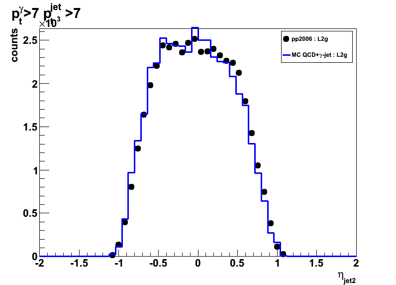
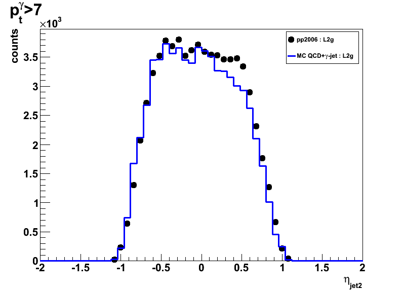
Figure 6:Photon pt


Figure 7: Away side jet pt


Figure 8: Pre-shower 1 energy
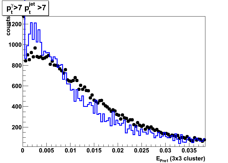
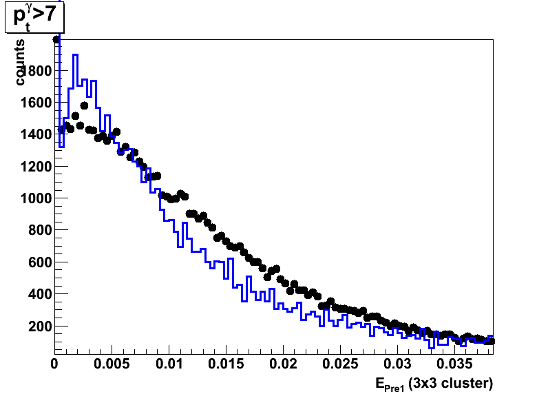
Figure 9: Pre-shower 2 energy
2009.02.06 Pre-shower energy distribution Run6 vs. Run8 geometry
Ilya Selyuzhenkov February 06, 2009
Data sets
- pp2006 - STAR 2006 pp longitudinal data (~ 3.164 pb^1)
Trigger: eemc-http-mb-L2gamma [id:137641] - mc2006: gamma-jet+QCD jets [p6410EemcGammaFilter] events.
- pp2008 - STAR 2008 pp data
Trigger: etot-mb-l2 [id:7]
Partonic pt range 2-25 GeV.
Cuts applied
- Di-jet events
- Require to reconstruct photon momentum (no gamma-jet isolation cuts)
- Gamma pt > 7GeV, jet pt > 7GeV
- L2gamma emulation in Monte-Carlo
- L2gamma triggered for pp2006 and pp2008 events
- cos (phi_jet - phi_gamma) < -0.8
- detector |eta_jet|< 0.8
- |v_z| < 100
Figures
Each figure has:
- All pre-shower conditions combined, No pre-shower cuts
- Red circles show pp2006 data
- Black triangles show pp2008 data
Data scaled to match the integraled yield from pp2006 data - Green line shows MC sum: QCD + gamma-jet
Monte-Carlo results for QCD and gamma-jet samples are first
scaled to 3.164 pb^-1 according to Pythia luminosity,
added together, and then an additional fudge factor of 1.24 applied.
Fudge factor is defined as pp2006 to Monte-Carlo sum ratio
for pt_jet>7GeV and pt_gamma>7 candidates
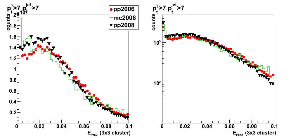
Observations
- Pre-shower energy distributions from pp2008 data set
are narrower than that for pp2006 data.
This corresponds to smaller amount of material budget in y2008 STAR geometry. - Pre-shower energy distribution from Monte-Carlo with y2006 geometry
closer follows the distribution from pp2008 data set, rather than that from pp2006 data.
This indicates the lack of material budget in y2006 Monte-Carlo.
Note: There is a "pre-shower sector 10 problem" for pp2008 data,
which results in migration of small fraction of events with pre-shower>0 into
pre-shower=0 bin (first zero bins in Fig.1 and 2. below).
For pre-shower>0 case this only affects overall normalization of pp2008 data,
but not the shape of pre-shower energy distributions.
I'm running jet-finder+my software to get more statistics from pp2008 data set,
and after more QA will produce list of runs with "pre-shower sector 10 problem",
so to exclude them in the next iteration of my plots.
Figure 1: Pre-shower1 energy distribution
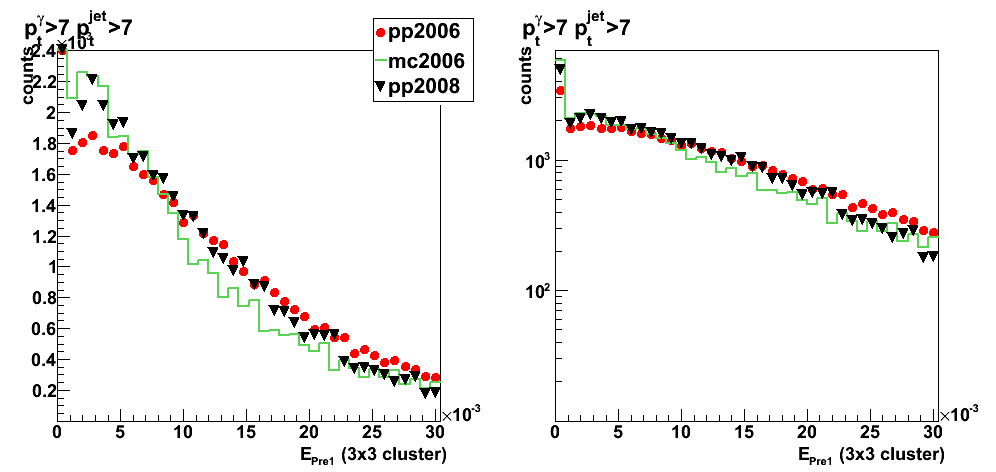
Figure 2: Pre-shower2 energy distribution
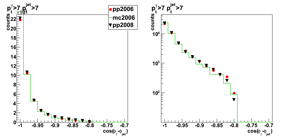
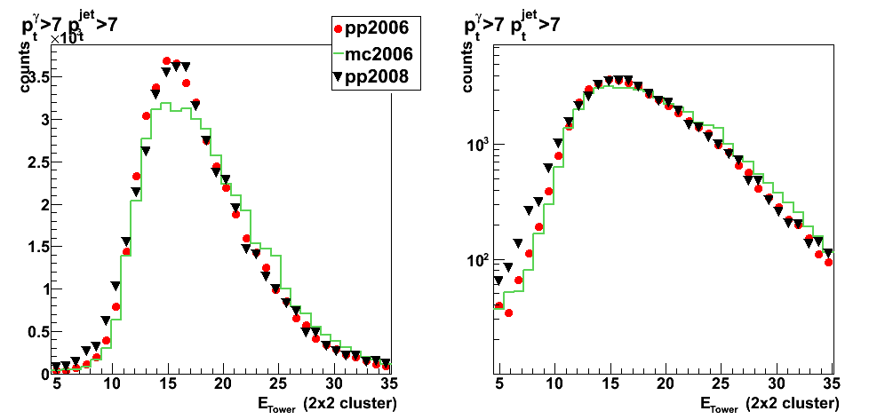
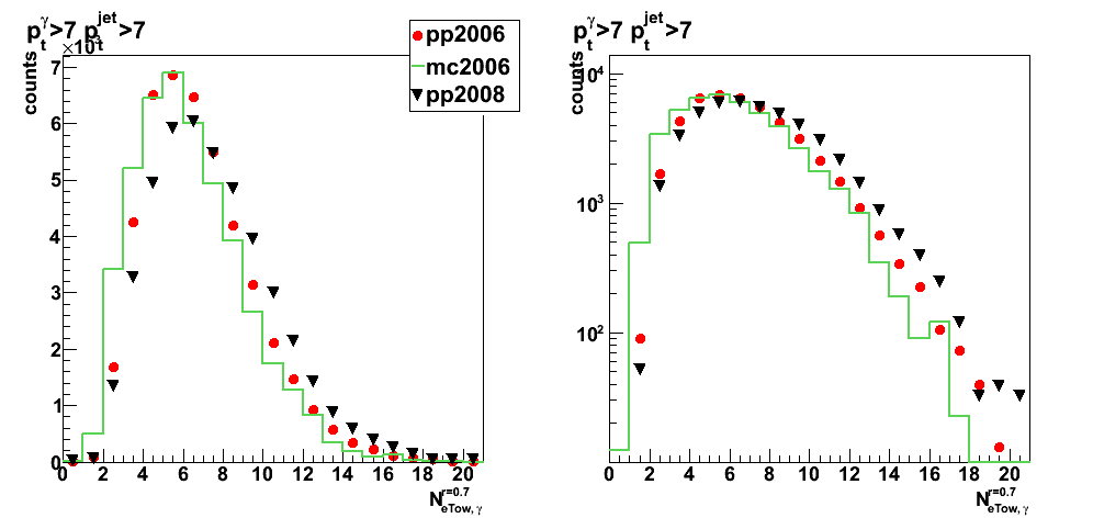
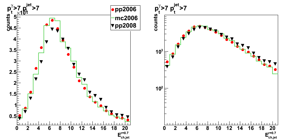
2009.02.09 pp2006, pp2008, amd mc2006 comparison
Ilya Selyuzhenkov February 06, 2009
Data sets
- pp2006 - STAR 2006 pp longitudinal data (~ 3.164 pb^1)
Trigger: eemc-http-mb-L2gamma [id:137641] - mc2006: gamma-jet+QCD jets [p6410EemcGammaFilter] events.
- pp2008 - STAR 2008 pp data
Trigger: etot-mb-l2 [id:7]
Partonic pt range 2-25 GeV.
Cuts applied
- Di-jet events
- Require to reconstruct photon momentum (no gamma-jet isolation cuts)
- Gamma pt > 7GeV, jet pt > 7GeV
- L2gamma emulation in Monte-Carlo
- L2gamma triggered for pp2006 and pp2008 events
- cos (phi_jet - phi_gamma) < -0.8
- detector |eta_jet|< 0.8
- |v_z| < 100
Figures
Each figure has:
- All pre-shower conditions combined, No pre-shower cuts
- Red circles show pp2006 data
- Black triangles show pp2008 data
Data scaled to match the integraled yield from pp2006 data - Green line shows MC sum: QCD + gamma-jet
Monte-Carlo results for QCD and gamma-jet samples are first
scaled to 3.164 pb^-1 according to Pythia luminosity,
added together, and then an additional fudge factor of 1.24 applied.
Fudge factor is defined as pp2006 to Monte-Carlo sum ratio
for pt_jet>7GeV and pt_gamma>7 candidates
Kinematics
Figure 1: vertex z
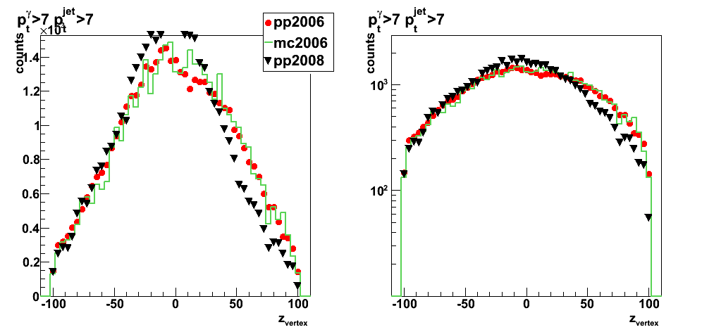
Figure 2: photon detector eta
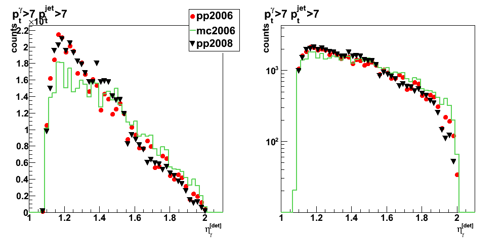
Figure 3: jet detector eta

Figure 4: photon pt

Figure 5: jet pt

Figure 6: gamma-jet pt balance
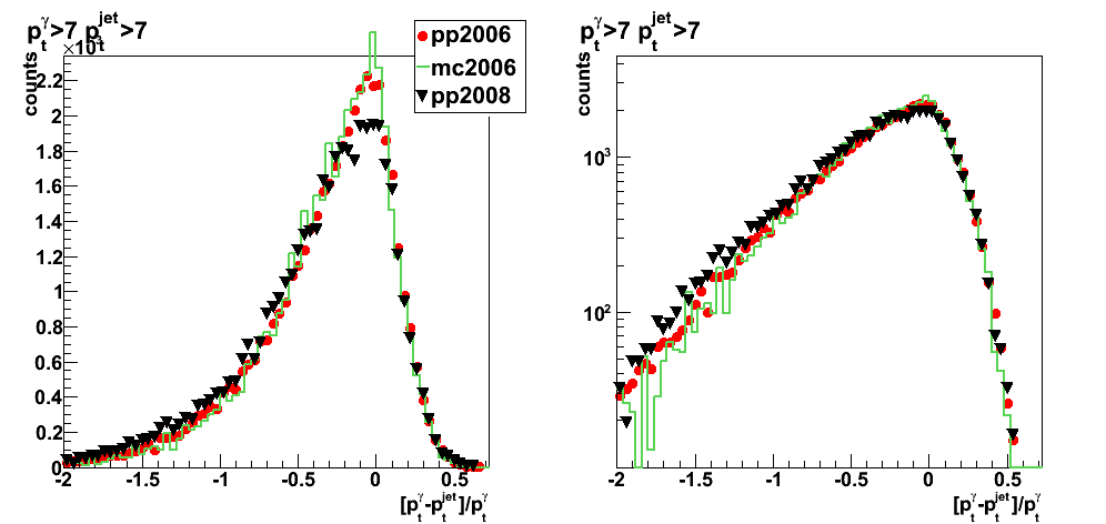
Figure 7: Photon neutral energy fraction
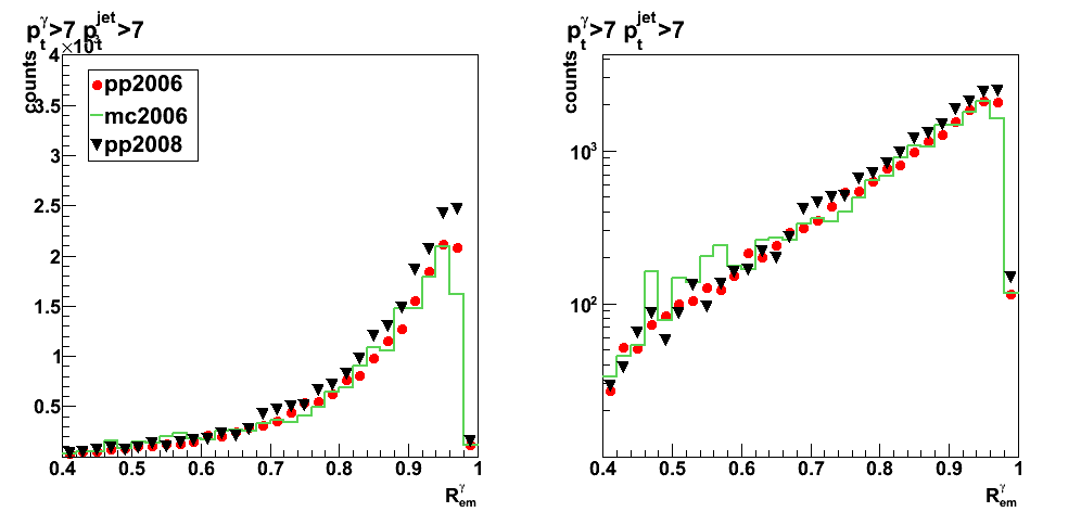
Figure 8: Jet neutral energy fraction

Figure 9: cos(phi_gamma-phi_jet)
Photon candidate's 2x1, 2x2, and 3x3 tower cluser energy
Figure 10: 3x3 cluster energy
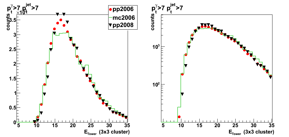
Figure 11: 2x1 cluster energy
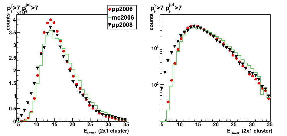
Figure 12: 2x2 cluster energy
Number of charge tracks, Barrel and Endcap towers within r=0.7 for photon and gamma
Figure 13: Number of charged track associated with photon candidate

Figure 14: Number of Barrel towers associated with photon candidate
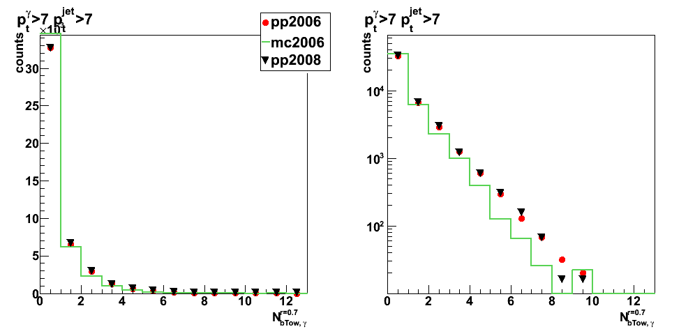
Figure 15: Number of Endcap towers associated with photon candidate
Jet energy composition
Figure 16: Jet energy part from Barrel towers
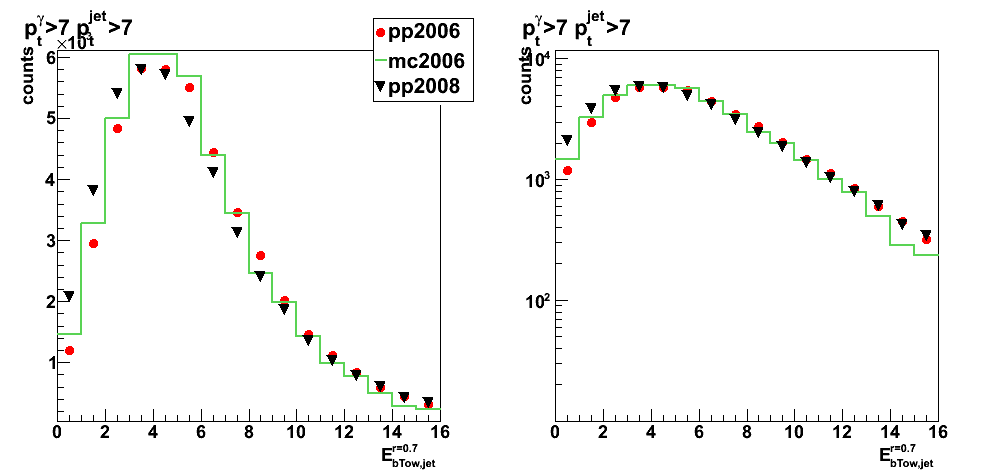
Figure 17: Jet energy part from charge tracks
2009.02.16 pt_jet>5GeV: pre-shower sorting with new normalization
Ilya Selyuzhenkov February 16, 2009
Data sets
- pp2006 - STAR 2006 pp longitudinal data (~ 3.164 pb^1)
Trigger: eemc-http-mb-L2gamma [id:137641] - mc2006: gamma-jet+QCD jets [p6410EemcGammaFilter] events.
- pp2008 - STAR 2008 pp data
Trigger: etot-mb-l2 [id:7]
Partonic pt range 2-25 GeV.
Cuts applied
- Di-jet events
- Require to reconstruct photon momentum (no gamma-jet isolation cuts)
- Gamma pt > 7GeV, jet pt > 7GeV
- L2gamma emulation in Monte-Carlo
- L2gamma triggered for pp2006 and pp2008 events
- cos (phi_jet - phi_gamma) < -0.8
- detector |eta_jet|< 0.8
- |v_z| < 100
Figures
Each figure has:
- pp2008 data scaled to match the integraled yield from pp2006 data
- mc2006 stand for MC sum: QCD + gamma-jet
Monte-Carlo results for QCD and gamma-jet samples are first
scaled to 3.164 pb^-1 according to Pythia luminosity,
added together, and then an additional fudge factor of 1.24 applied.
Fudge factor is defined as pp2006 to Monte-Carlo sum ratio
for pt_jet>7GeV and pt_gamma>7 candidates
plots for pt_gamma>7GeV, pt_jet > 5GeV
- All pre-shower combined: 1D distributions
- All pre-shower combined: 2D correlations
- Pre-shower sorting 1D distributions
2009.02.19 Photon-jet analysis status update for Spin PWG
Photon-jet analysis status update for Spin PWG (February 19, 2009)
Slides: download pdf
Link for CIPANP abstract
CIPANP 2009 abstract on photon-jet measurement
CIPANP 2009 abstract on photon-jet study
Title:
"Photon-jet coincidence measurements
in polarized pp collisions at sqrt{s}=200GeV
with the STAR Endcap Calorimeter"
Abstract: download pdf
Previous versions: v1, v2, v3, v4
Conference link: CIPANP 2009
03 Mar
March 2009 posts
2009.03.02 Application of the neural network for the cut optimization (zero try)
Multilayer perceptron (feedforward neural networks)
Multilayer perceptron (MLP) is feedforward neural networks
trained with the standard backpropagation algorithm.
They are supervised networks so they require a desired response to be trained.
They learn how to transform input data into a desired response,
so they are widely used for pattern classification.
With one or two hidden layers, they can approximate virtually any input-output map.
They have been shown to approximate the performance of optimal statistical classifiers in difficult problems.
ROOT implementation for Multilayer perceptron
TMultiLayerPerceptron class in ROOT
mlpHiggs.C example
Application for cuts optimization in the gamma-jet analysis
Netwrok structure:
r3x3, (pt_gamma-pt_jet)/pt_gamma, nCharge, bBtow, eTow2x1: 10 hidden layers: one output later
Figure 1:
- Upper left: Learning curve (error vs. number of training)
Learing method is: Steepest descent with fixed step size (batch learning) - Upper right: Differences (how important are initial variableles for signal/background separation)
- Lower left: Network structure (ling thinkness corresponds to relative weight value)
- Lower right: Network output. Red - MC gamma-jets, blue QCD background, black pp2006 data
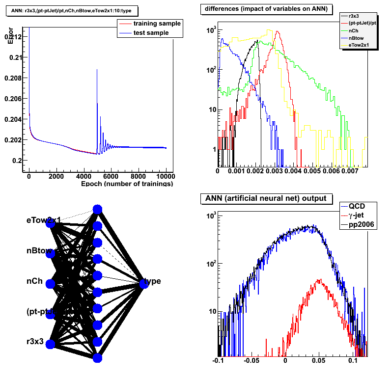
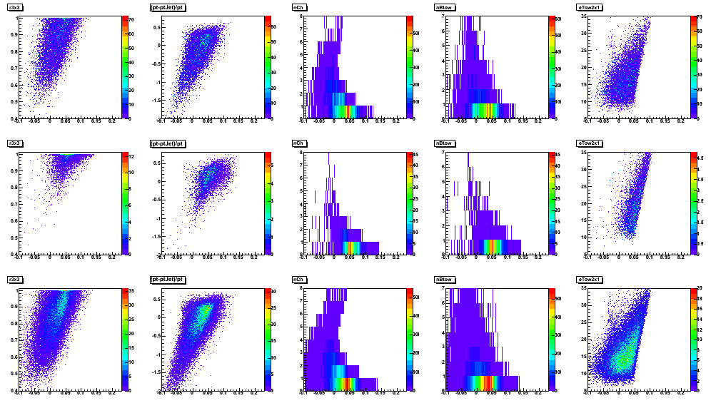
Figure 2: Input parameters vs. network output
Row: 1: MC QCD, 2: gamma-jet, 3 pp2006 data
Vertical axis: r3x3, (pt_gamma-pt_jet)/pt_gamma, nCharge, bBtow, eTow2x1
Horisontal axis: network output
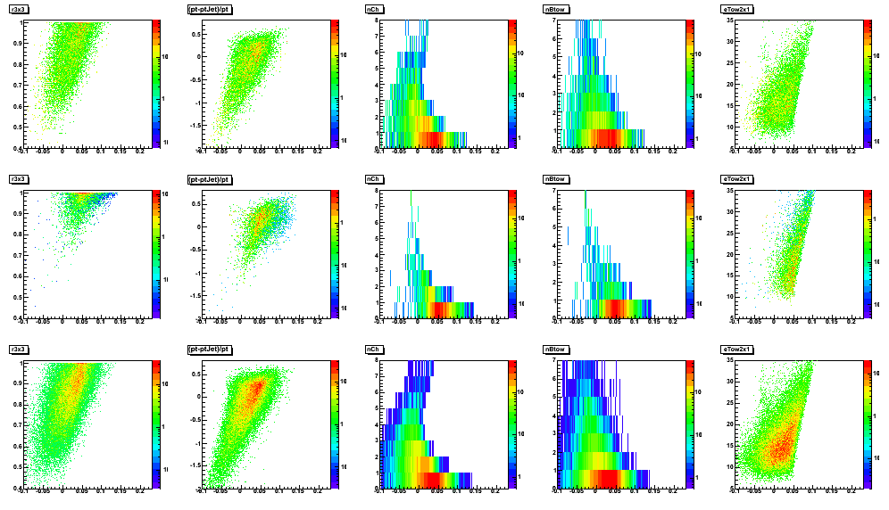
Figure 3: Same as Fig. 2 on a linear scale
2009.03.09 Application of the LDA and MLP classifiers for the cut optimization
Cut optimization with Fisher's LDA and MLP (neural network) classifiers
ROOT implementation for LDA and MLP:
- Fisher's Linear Discriminant Analysis (LDA)
- Multi-Layer Perceptron (MLP) [feed-forward neural network]
Application for cuts optimization in the gamma-jet analysis
LDA configuration: default
MLP configuration:
- 2 hidden layers [N+1:N neural network configuration, N is number of input parameters]
- Learning method: stochastic minimization (1000 learning cycles)
Input parameters (same for both LDA and MLP):
- Energy fraction in 3x3 cluster within a r=0.7 radius: r3x3
- Photon-jet pt balance: [pt_gamma-pt_jet]/pt_gamma
- Number of charge tracks within r=0.7 around gamma candidate
- Number of Endcap towers fired within r=0.7 around gamma candidate
- Number of Barrel towers fired within r=0.7 around gamma candidate
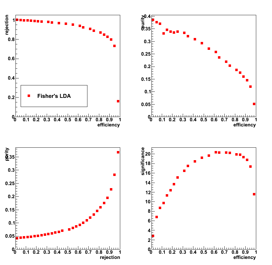
Figure 1: Signal efficiency and purity, background rejection (left),
and significance: Sig/sqrt[Sig+Bg] (right) vs. LDA (upper plots) and MLP (lower plots) classifier discriminants

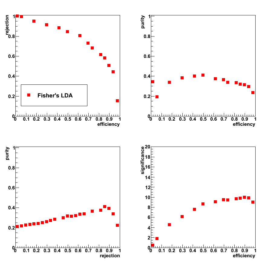
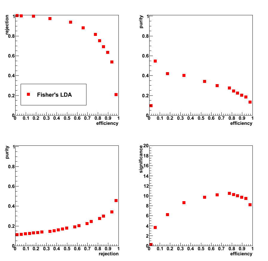
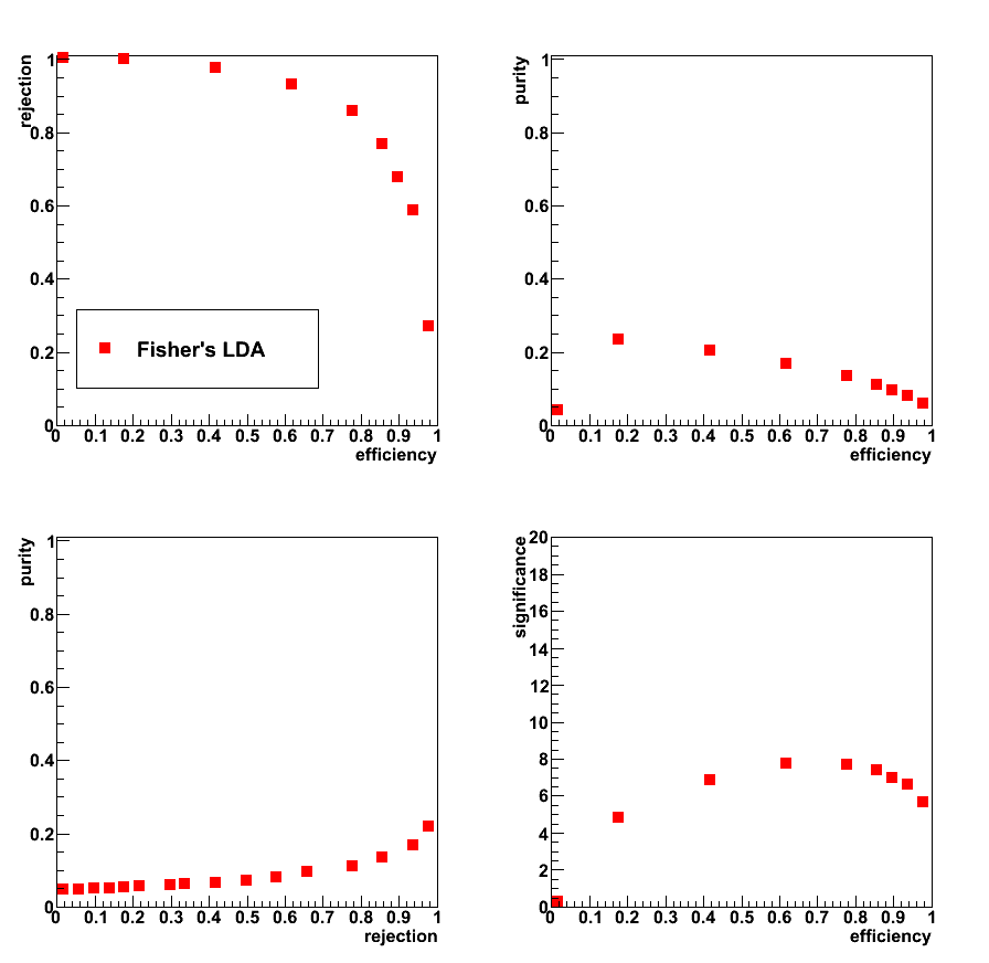
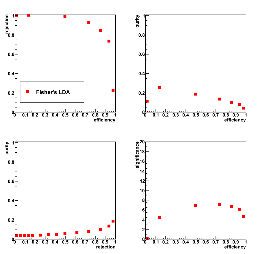
Figure 2:
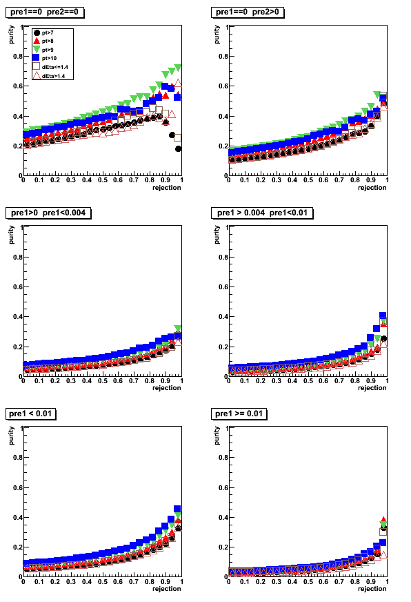
- Upper left: Rejection vs. efficiency
- Upper right: Purity vs. efficiency
- Lower left: Purity vs. Rejection
- Lower right: Significance vs. efficiency
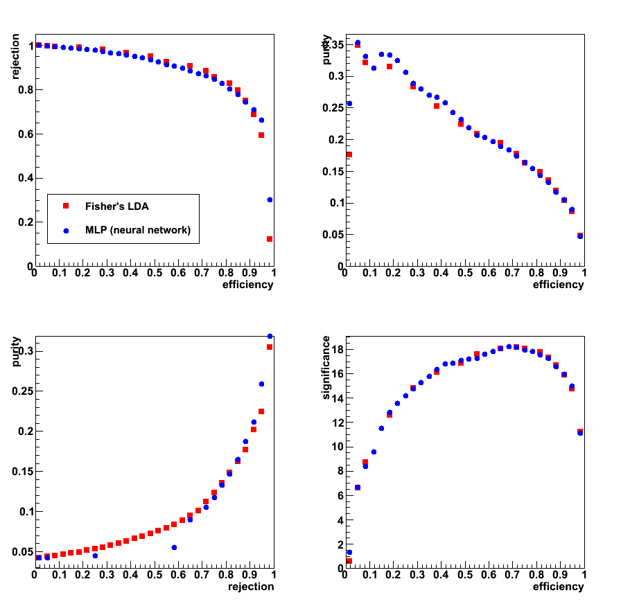
Figure 3: Data to Monte-Carlo comparison for LDA (upper plots) and MLP (lower plots)
Good (within ~ 10%) match between data nad Monte-Carlo
a) up to 0.8 for LDA discriminant, and b) up to -0.7 for MLP.
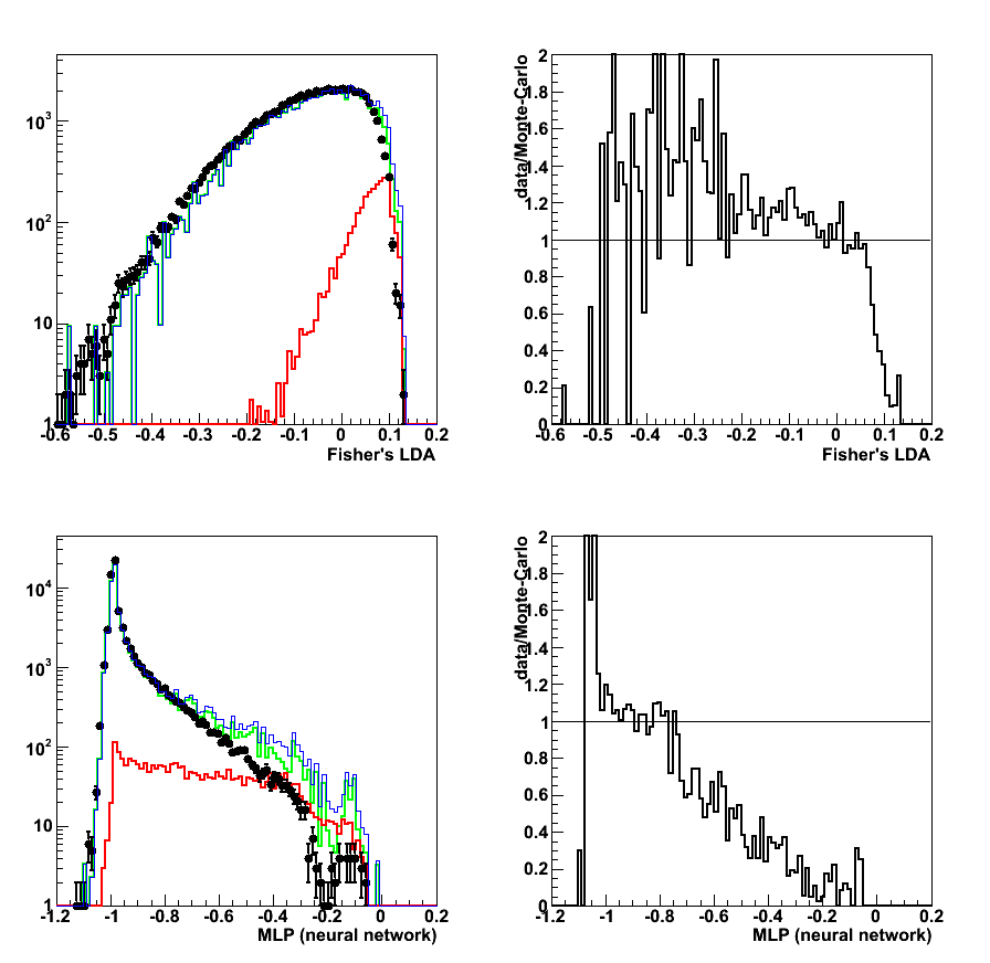
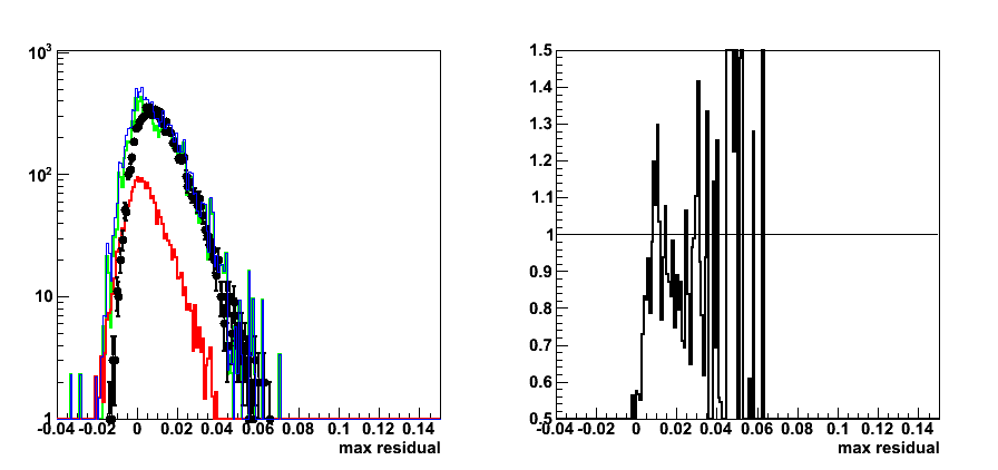
Figure 4: Data to Monte-Carlo comparison for input parameters
from left to right
1) pt_gamma 2) pt_jet 3) r3x3 4) gamma-jet pt balance 5) N_ch[gamma] 6) N_eTow[gamma] 7) N_bTow[gamma]
Colour coding: black pp2006 data, red gamma-jet MC, green QCD MC, blue gamma-jet+QCD
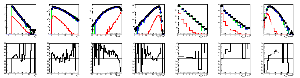
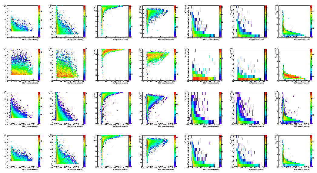
Figure 5: Data to Monte-Carlo comparison:
correlations between input variables (in the same order as in Fig. 4)
and LDA classifier discriminant (horizontal axis).
1st raw: QCD MC; 2nd: gamma-jet MC; 3rd: pp2006 data; 4th: QCD+gamma-jet MC
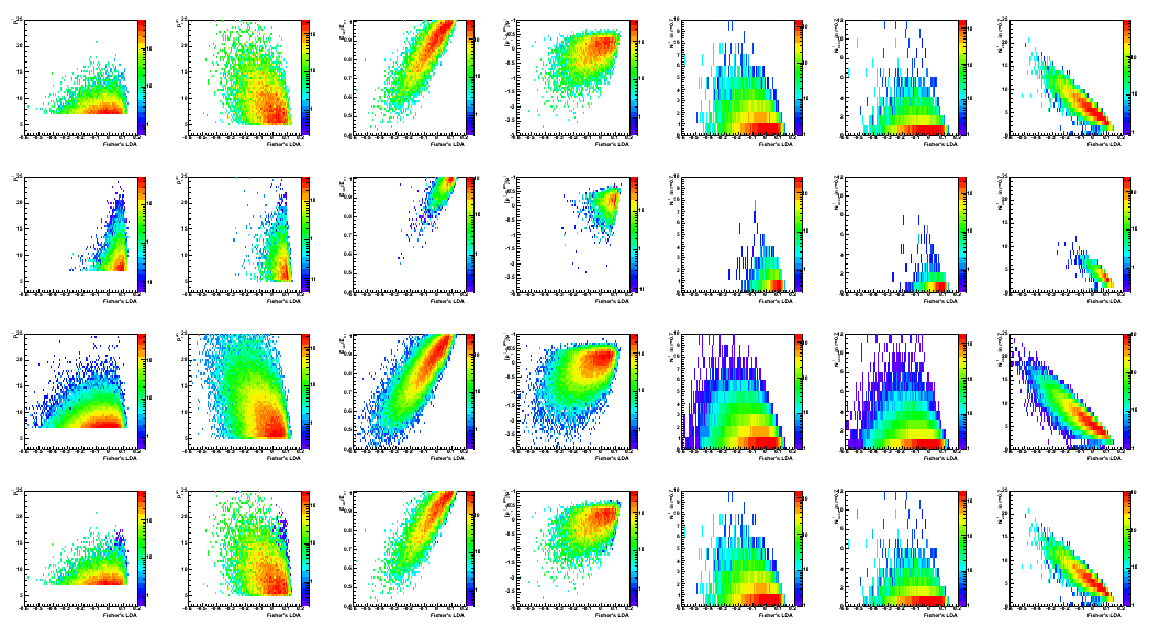
Figure 6: Same as Fig. 6 for MLP discriminant
2009.03.26 Endcap photon-jet update at the STAR Collaboration meeting
Endcap photon-jet update at the STAR Collaboration meeting
04 Apr
April 2009 posts
2009.04.17 WSU nuclear seminar
The STAR spin program with longitudinally polarized proton beams
2009.04.21 Adding SMD info to the LDA
Cut optimization with Fisher's LDA classifier
ROOT implementation for LDA:
Application for cuts optimization in the gamma-jet analysis
LDA configuration: default
LDA input parameters:
- Energy fraction in 3x3 cluster within a r=0.7 radius: r3x3
- Photon-jet pt balance: [pt_gamma-pt_jet]/pt_gamma
- Number of charge tracks within r=0.7 around gamma candidate
- Number of Endcap towers fired within r=0.7 around gamma candidate
- Number of Barrel towers fired within r=0.7 around gamma candidate
Figure 1: LDA discriminant (no SMD involved in training)
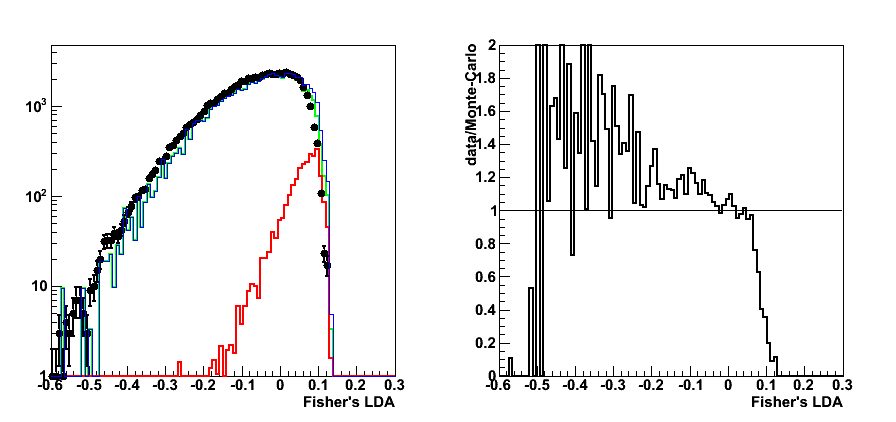
Figure 2: LDA (no SMD): Efficiency, rejection, purity vs. discriminant

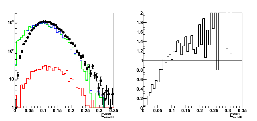
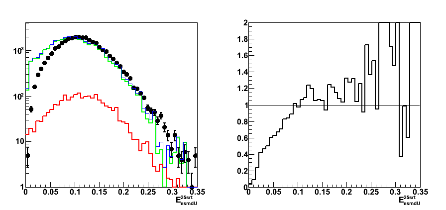
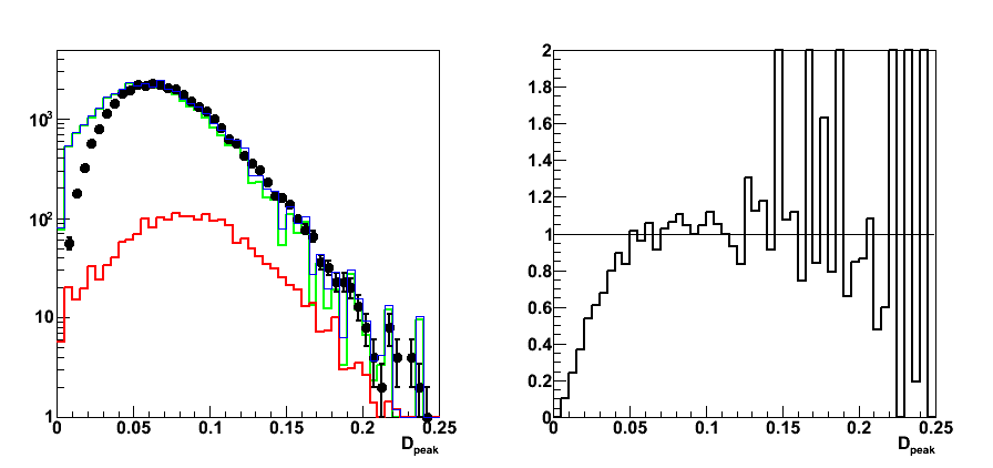
Figure 3: SMD energy in 25 central strips (LDA-dsicriminant>0, no pre-shower1 cut)
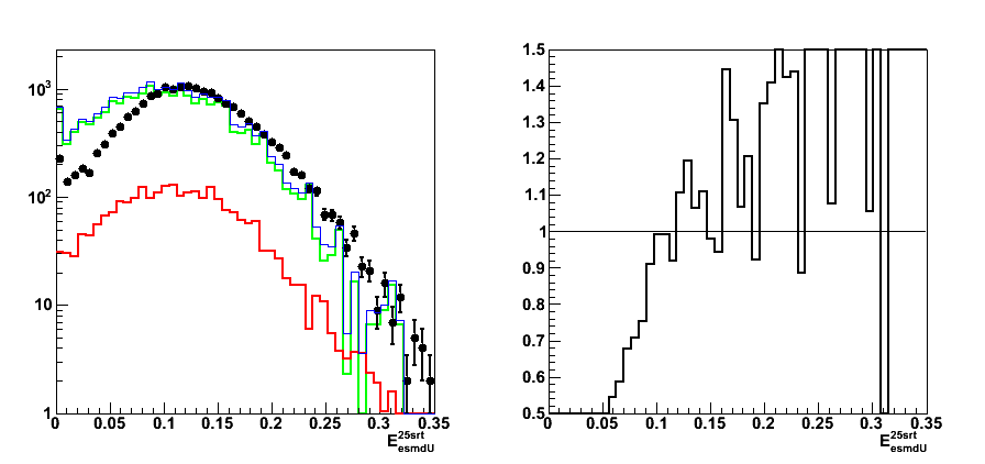
Figure 4: SMD energy in 25 central strips (LDA-dsicriminant>0, pre-shower1 < 10MeV)
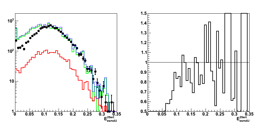
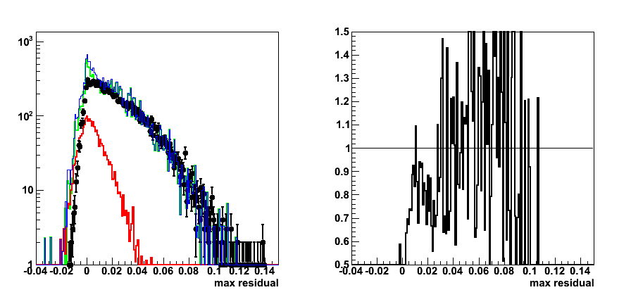
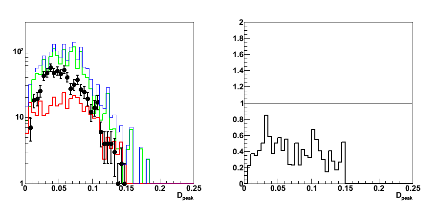
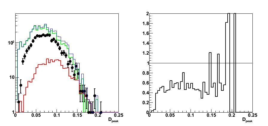
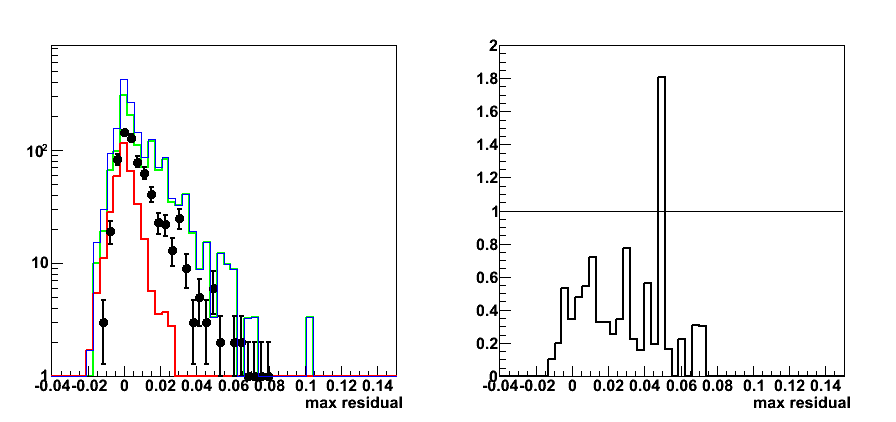
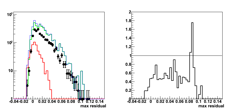
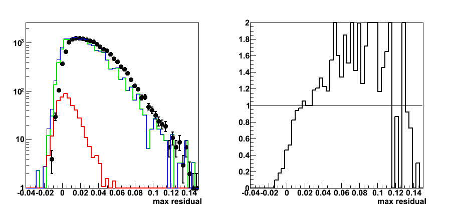
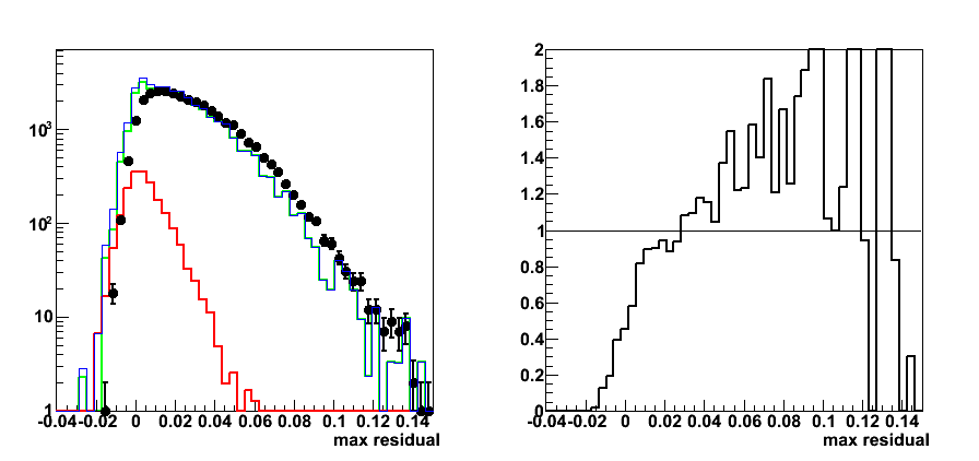
Figure 5: Maximum residual (LDA-dsicriminant>0, no pre-shower1 cut)
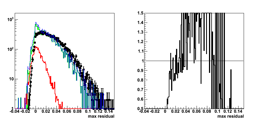
Figure 6: Maximum residual (LDA-dsicriminant>0, pre-shower1 < 10MeV)
LDA+ SMD analysis
SMD info added:
a) energy in 5 central srtips
b) maximum sided residual
Figure 7:LDA with SMD: Efficiency, rejection, purity vs. LDA discriminant
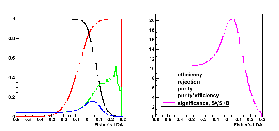
Figure 8: LDA discriminant with SMD
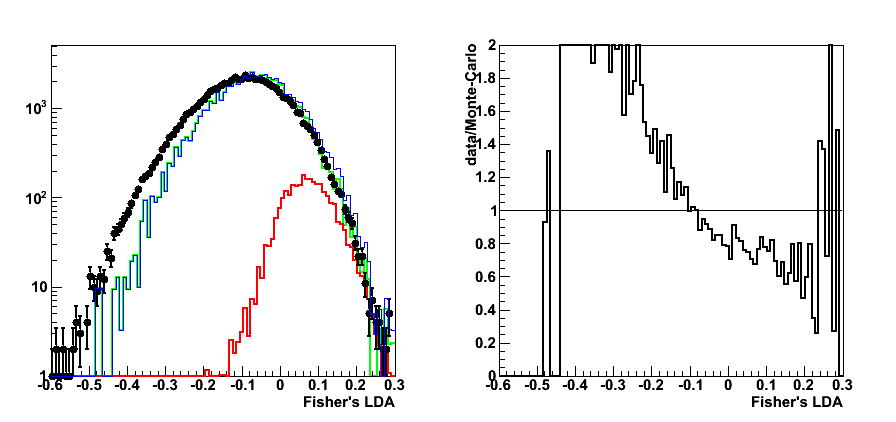
Figure 9: Maximum residual (SMD LDA-dsicriminant>0, pre-shower1 < 10MeV)
LDA with and without SMD comparison
Figure 10:LDA (no SMD): Efficiency, rejection, purity plots
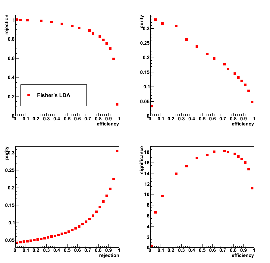
Figure 11: LDA with SMD: Efficiency, rejection, purity plots
2009.04.28 LDA plus SMD analysis with pre-shower sorting
Cut optimization with Fisher's LDA classifier
ROOT implementation for LDA:
Application for cuts optimization in the gamma-jet analysis
LDA configuration: default
LDA input parameters (includes SMD inromation of the distance from max sided residual plot):
- Energy fraction in 3x3 cluster within a r=0.7 radius: r3x3
- Photon-jet pt balance: [pt_gamma-pt_jet]/pt_gamma
- Number of charge tracks within r=0.7 around gamma candidate
- Number of Endcap towers fired within r=0.7 around gamma candidate
- Number of Barrel towers fired within r=0.7 around gamma candidate
- Distance to 80% cut line (see this link for more details)
The number of strips in SMD u or v planes is required to be greater than 3
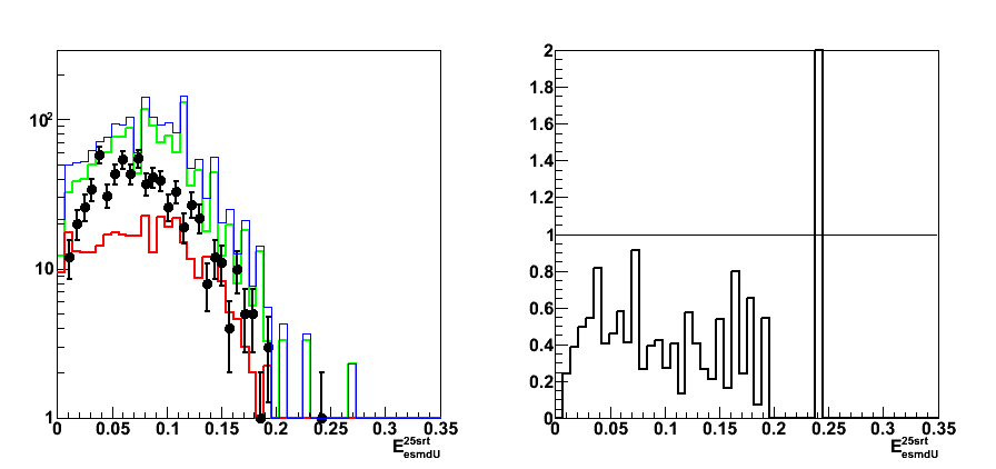
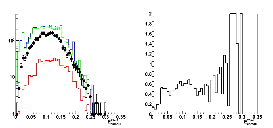
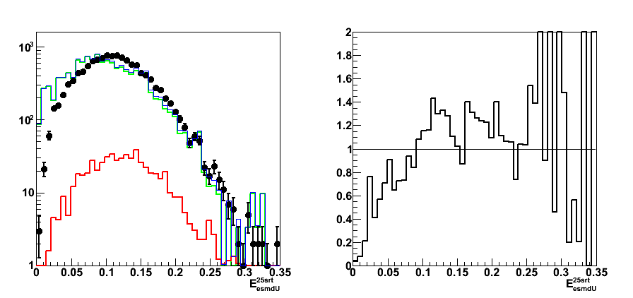
Figure 1: SMD energy in 25 central strips sorted by pre-shower energy
- Upper left: pre1=0, pre2=0
- Upper right: pre1=0, pre2>0
- Lower left: 0<4MeV
- Lower right: 4<10MeV
Right plot for each pre-shower condition shows the ratio of pp2006 data to sum of the Monte-Carlo samples
Colour coding:
black pp2006 data, red gamma-jet MC, green QCD MC, blue gamma-jet+QCD
(combined plot for all pre-shoer bins can be found here)
Figure 2: SMD energy in 5 central strips sorted by pre-shower energy
(combined plot can be found here)


Figure 3: Maximum residual sorted by pre-shower energy
(combined plot can be found here)

Figure 4: LDA discriminant. Note: LDA algo trained for each pre-shower condition independently


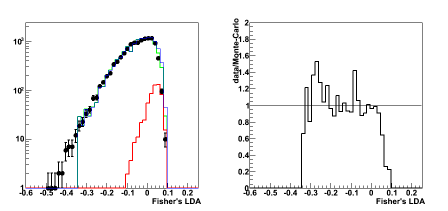

Figure 5: LDA: Efficiency, rejection, purity vs. discriminant, sorted by pre-shower energy
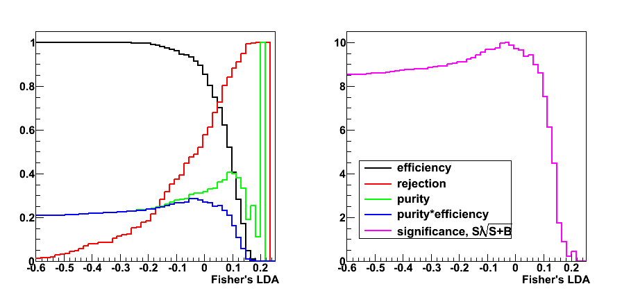


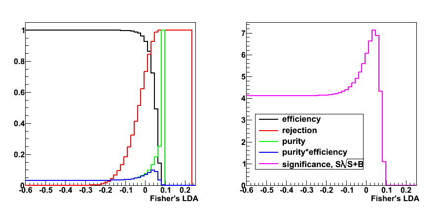
Figure 6: LDA: Efficiency, rejection, purity plots sorted by pre-shower energy
For each pre-shower condition each plot has 4 figures:
- u-left: rejection vs. efficiency
- u-right: purity vs. efficiency
- l-left: purity vs. rejection
- l-right: significance (signal/sqrt{signal+background}) vs. efficiency
05 May
May 2009 posts
2009.05.03 LDA: varying pt and eta cut
Cut optimization with Fisher's LDA classifier
ROOT implementation for LDA:
Application for cuts optimization in the gamma-jet analysis
LDA configuration: default
LDA input parameters Set0:
- Set0:
- Energy fraction in 3x3 cluster within a r=0.7 radius:
E_3x3/E_0.7 - Photon-jet pt balance:
[pt_gamma-pt_jet]/pt_gamma - Number of charge tracks within r=0.7 around gamma candidate:
Ncharge - Number of Endcap towersL fired within r=0.7 around gamma candidate:
NtowBarrel - Number of Barrel towers fired within r=0.7 around gamma candidate
NtowEndcap
- Energy fraction in 3x3 cluster within a r=0.7 radius:
- Set1:
- All from Set0
- Shower shape analysis: distance to 80% cut line:
distance to cut line
- Set2:
- All from Set1
- Energy fraction in E_2x1 and E_2x2 witin E_3x3:
E_2x1/E_2x2 and E_2x2/E_3x3
- Set3:
- All from Set2
- Energy in post-shower layer under 3x3 tower patch:
E_post^3x3
The number of strips in SMD u or v planes is required to be greater than 3
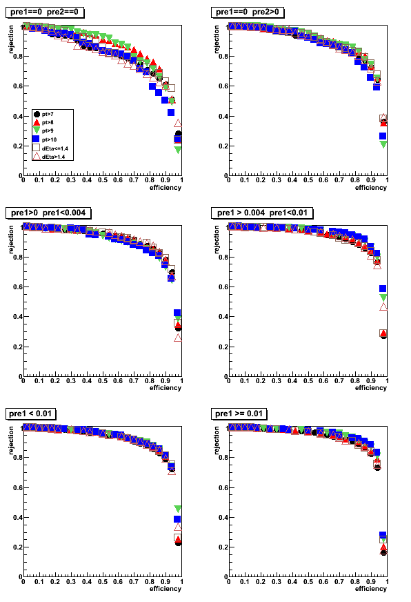
Pre-shower sorting (energy in tiles under 3x3 tower patch):
- pre1=0, pre2=0
- pre1=0, pre2>0
- 0 < pre1 < 0.004
- 0.004 < pre1 < 0.01
- pre1 < 0.01
- pre1 >= 0.01
Photon pt and rapidity cuts:
- pt>7GeV
- pt>8GeV
- pt>9GeV
- pt>10GeV
- detector eta <1.4 (pt>7GeV)
- detector eta > 1.4 (pt>7GeV)
Figure 0: photon pt distribution for pre-shower1<0.01
Colour coding:
black pp2006 data, red gamma-jet MC, green QCD MC, blue gamma-jet+QCD
LDA Set0
Figure 1: LDA discriminant with Set0: Data to Monte-Carlo comparison (pt>7GeV cut)
Right plot for each pre-shower condition shows the ratio of pp2006 data to sum of the Monte-Carlo samples
Colour coding:
black pp2006 data, red gamma-jet MC, green QCD MC, blue gamma-jet+QCD
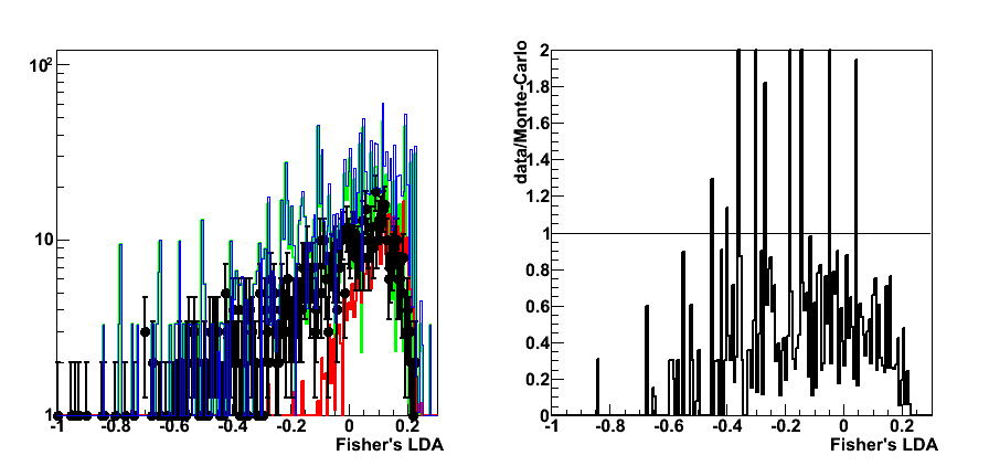
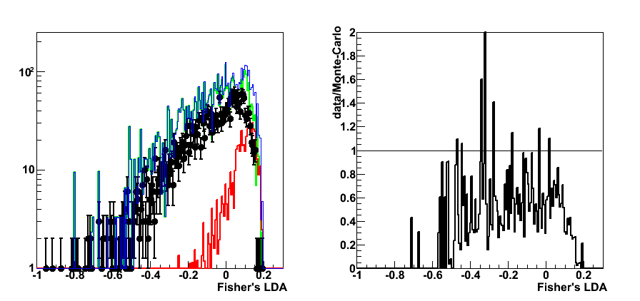
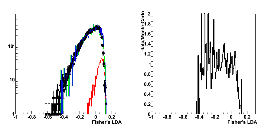
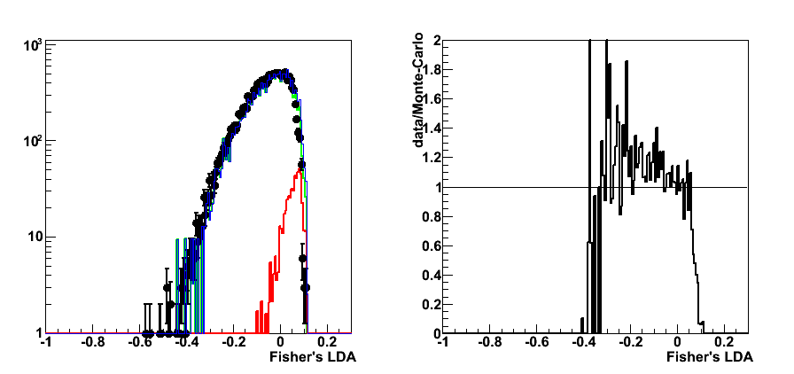
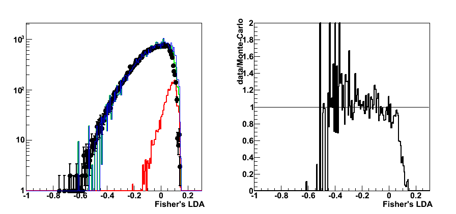
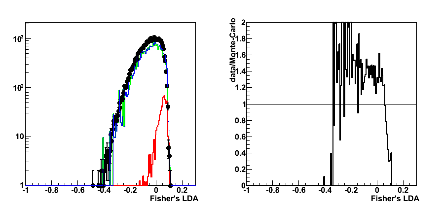
Figure 2: efficiency, purity, rejection vs. LDA discriminant (pt>7GeV cut)
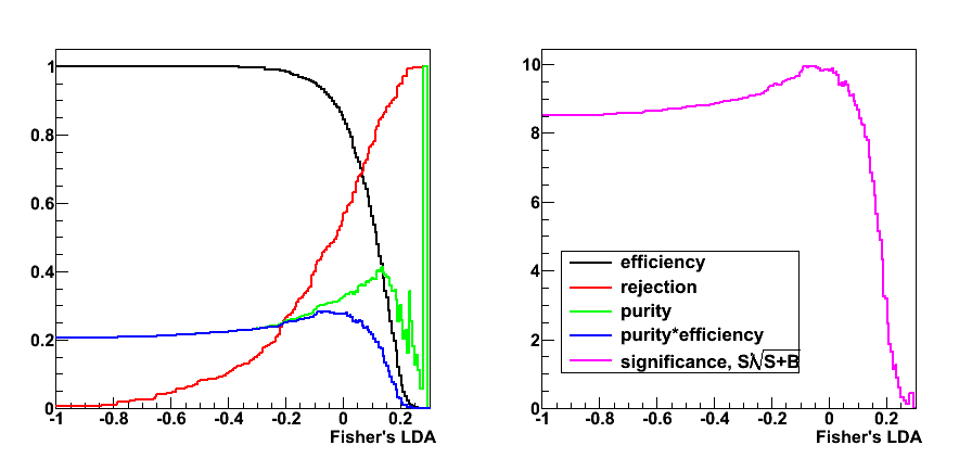
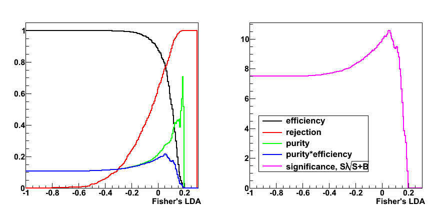


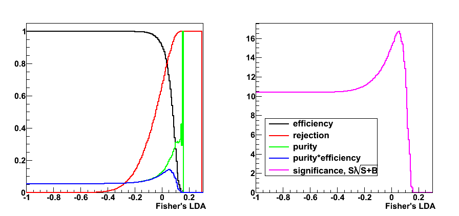
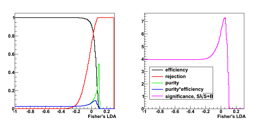
Figure 3: rejection vs. efficiency
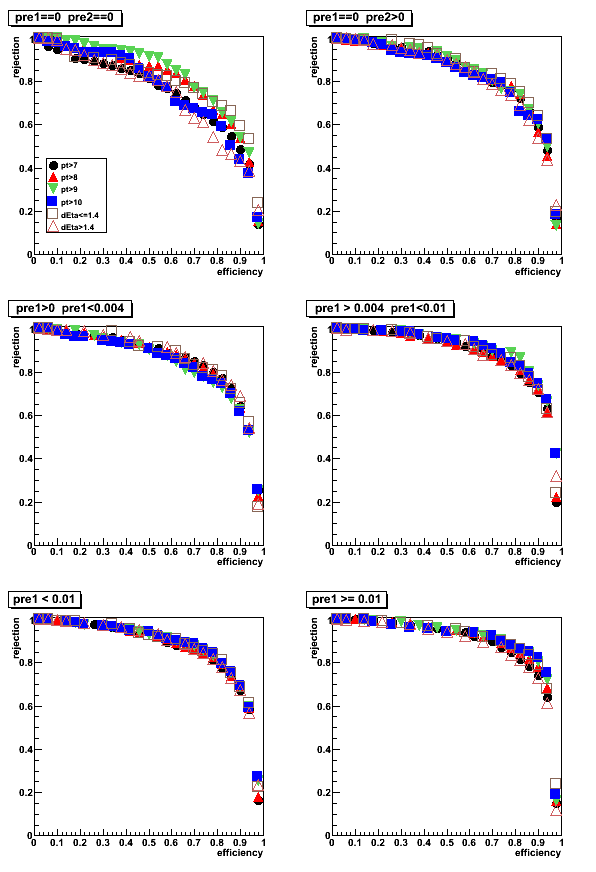
Figure 4: purity vs. efficiency
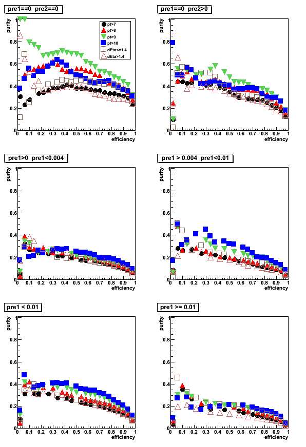
Figure 5: purity vs. rejection
LDA Set1
Figure 6: LDA discriminant with Set1: Data to Monte-Carlo comparison
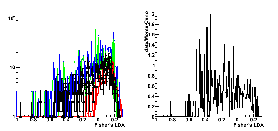
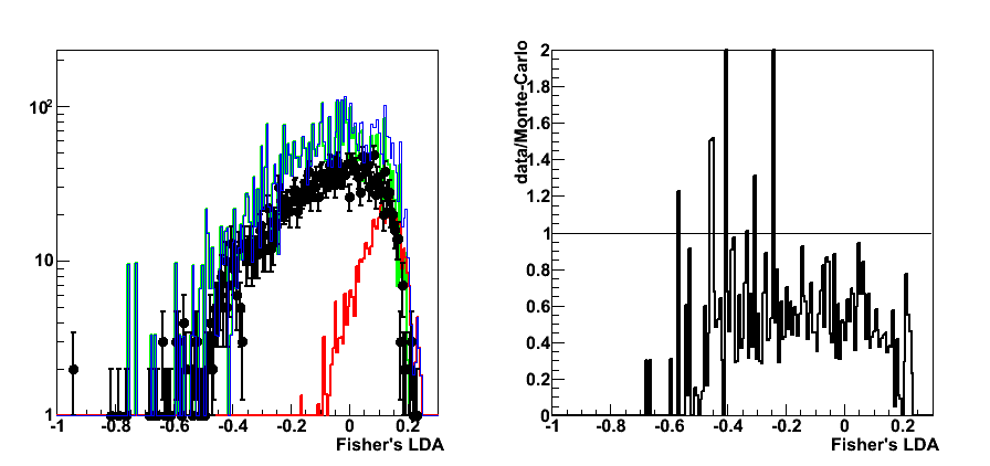
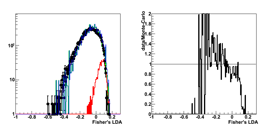
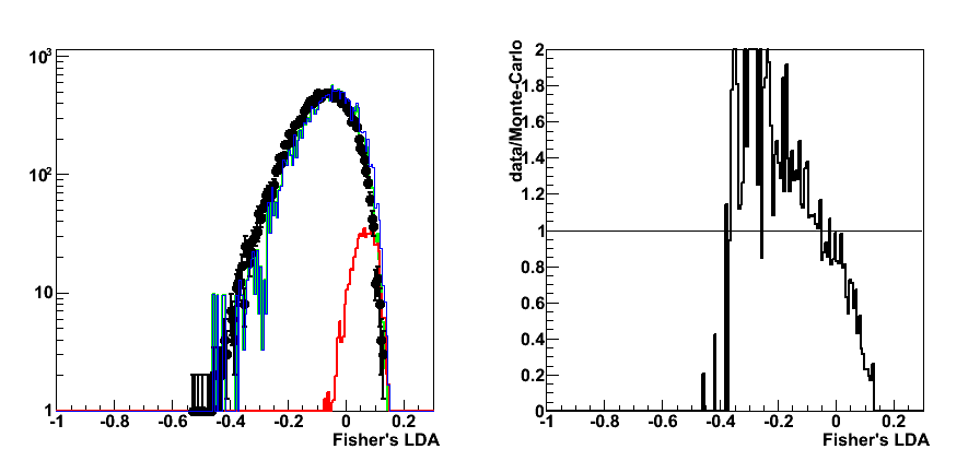
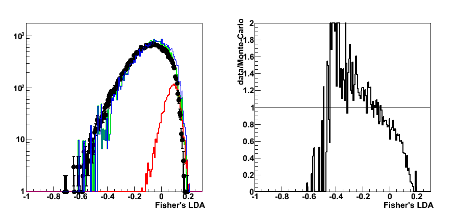

Figure 7: rejection vs. efficiency
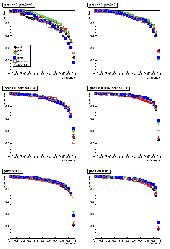
Figure 8: purity vs. efficiency

Figure 9: purity vs. rejection (click link to see the figure)
LDA Set2
Figure 10: rejection vs. efficiency (click link to see the figure)
Figure 11: purity vs. efficiency
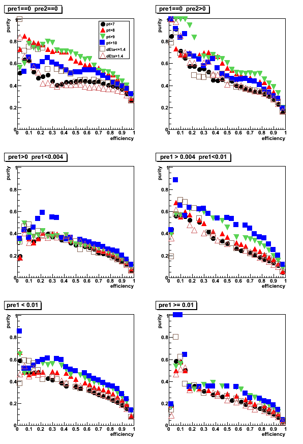
Figure 12: purity vs. rejection (click link to see the figure)
LDA Set3
Figure 13: rejection vs. efficiency (click link to see the figure)
Figure 14: purity vs. efficiency
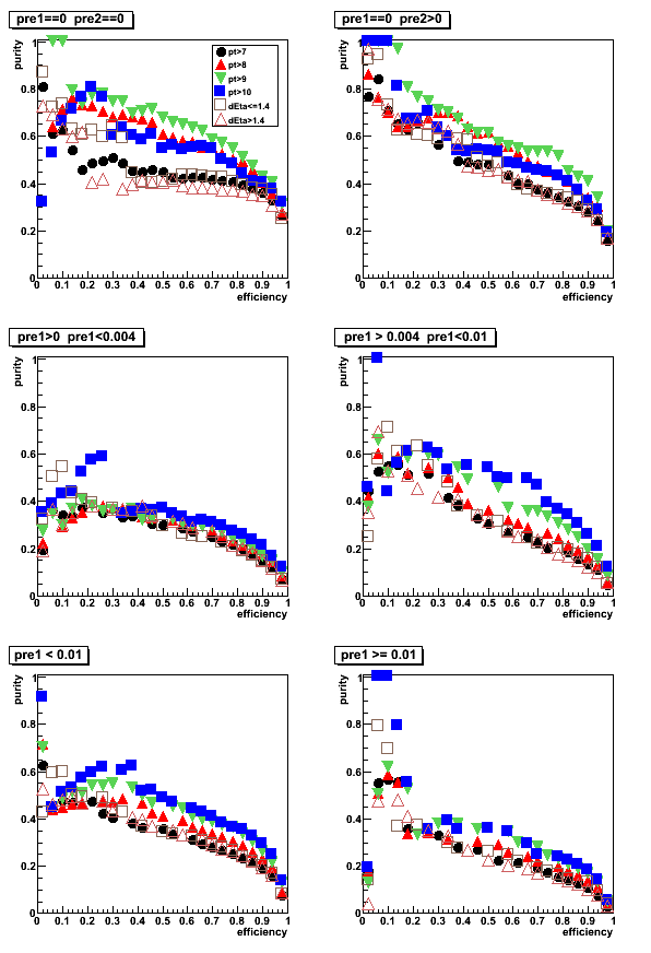
Figure 15: purity vs. rejection (click link to see the figure)
2009.05.04 LDA: More SMD info, 3x3 tower energy, correlation matrix
Cut optimization with Fisher's LDA classifier
ROOT implementation for LDA:
Application for cuts optimization in the gamma-jet analysis
LDA configuration: default
LDA input parameters Set0:
- Set4 (link for results with LDA Set0-Set3):
- Energy fraction in 3x3 cluster within a r=0.7 radius:
E_3x3/E_0.7 - Photon-jet pt balance:
[pt_gamma-pt_jet]/pt_gamma - Number of charge tracks within r=0.7 around gamma candidate:
Ncharge - Number of Endcap towersL fired within r=0.7 around gamma candidate:
NtowBarrel - Number of Barrel towers fired within r=0.7 around gamma candidate
NtowEndcap - Shower shape analysis: distance to 80% cut line:
distance to cut line - Energy fraction in E_2x1 and E_2x2 witin E_3x3:
E_2x1/E_2x2 and E_2x2/E_3x3 - Energy in post-shower layer under 3x3 tower patch:
E_post^3x3 - Tower energy in 3x3 patch:
E_tow^3x3 - SMD-u energy in 25 central strips:
E_smd-u^25 - SMD-v energy in 25 central strips:
E_smd-v^25 - SMD-v peak energy (in 5 central strips):
E_peak
- Energy fraction in 3x3 cluster within a r=0.7 radius:
The number of strips in SMD u or v planes is required to be greater than 3
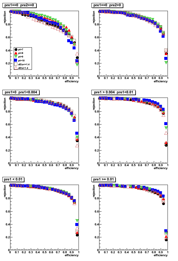
Pre-shower sorting (energy in tiles under 3x3 tower patch):
- pre1=0, pre2=0
- pre1=0, pre2>0
- 0 < pre1 < 0.004
- 0.004 < pre1 < 0.01
- pre1 < 0.01
- pre1 >= 0.01
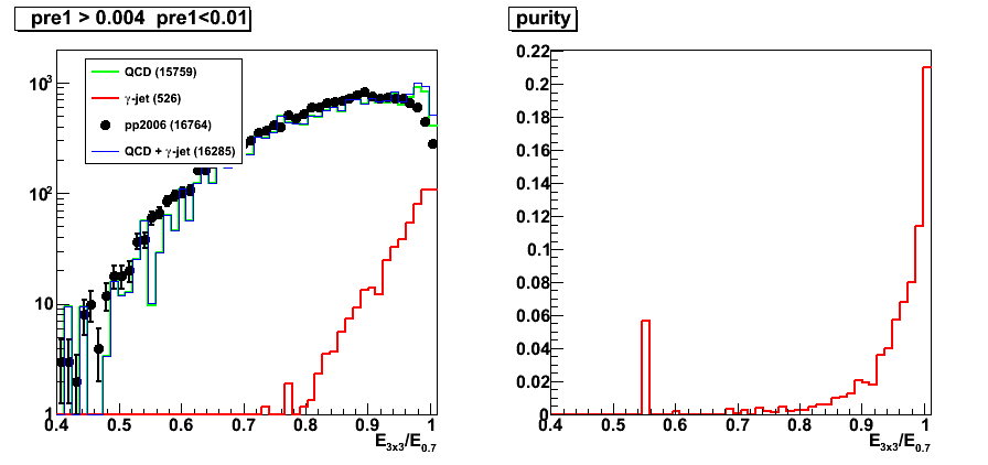
Integrated yields per pre-shower bin:
| sample | total integral | pre1=0,pre2=0 | pre1=0, pre2>0 | 0 < pre1 < 0.004 | 0.004 < pre1 < 0.01 | pre1 < 0.01 | pre1 >= 0.01 |
| photon-jet | 2.5640e+03 | 3.5034e+02 | 5.2041e+02 | 5.6741e+02 | 5.2619e+02 | 1.9644e+03 | 5.9994e+02 |
| QCD | 5.6345e+04 | 1.3515e+03 | 4.3010e+03 | 1.2289e+04 | 1.5759e+04 | 3.3701e+04 | 2.2644e+04 |
| pp2006 | 6.2811e+04 | 6.8000e+02 | 2.4310e+03 | 1.2195e+04 | 1.6766e+04 | 3.2072e+04 | 3.0739e+04 |
Photon pt and rapidity cuts:
- pt>7GeV
- pt>8GeV
- pt>9GeV
- pt>10GeV
- detector eta <1.4 (pt>7GeV)
- detector eta > 1.4 (pt>7GeV)
LDA Set4
Figure 1: LDA discriminant with Set0: Data to Monte-Carlo comparison (pt>7GeV cut)
Right plot for each pre-shower condition shows the ratio of pp2006 data to sum of the Monte-Carlo samples
Colour coding:
black pp2006 data, red gamma-jet MC, green QCD MC, blue gamma-jet+QCD
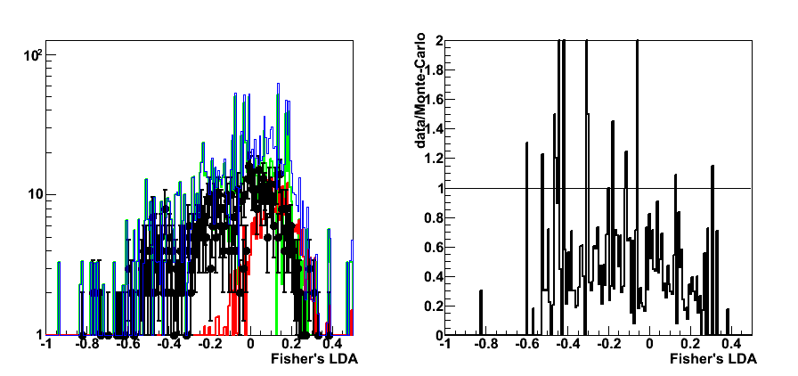
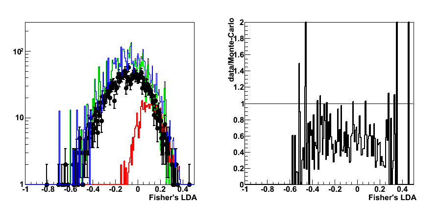
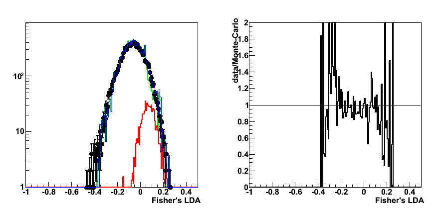
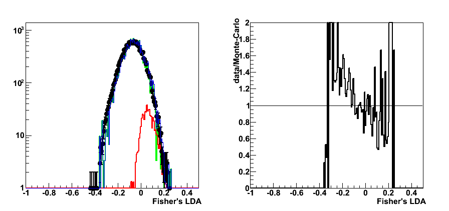
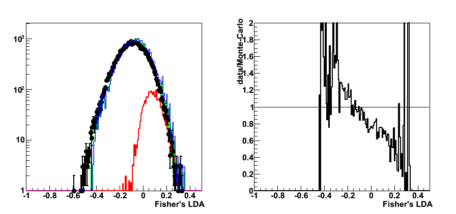
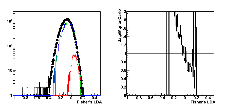
Figure 2: rejection vs. efficiency
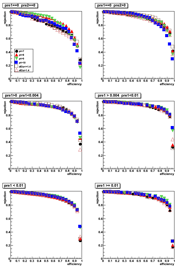
Figure 3: purity vs. efficiency

Figure 4: purity vs. rejection
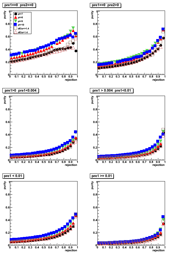
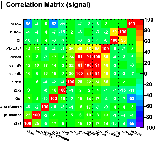
Figure 5: Correlation matrix (pt>7GeV cut)
pre1=0, pre2=0
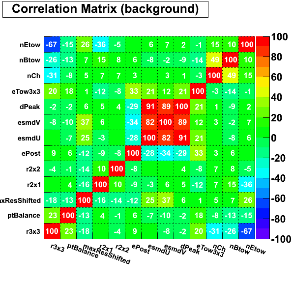
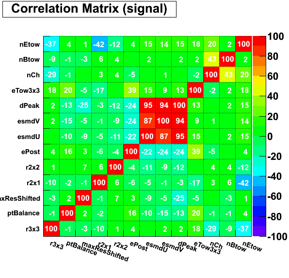
pre1=0, pre2>0

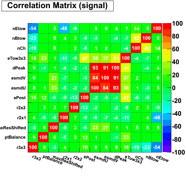
0 < pre1 < 0.004


0.004 < pre1 < 0.01
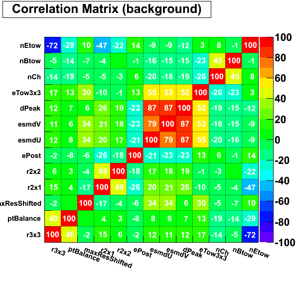

pre1 < 0.01
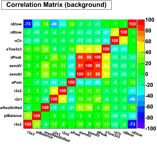
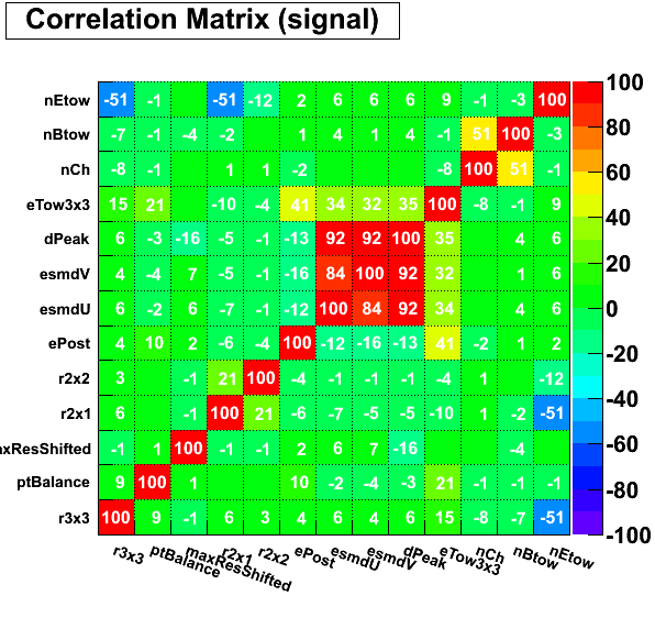
pre1 >= 0.01

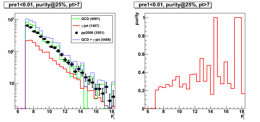
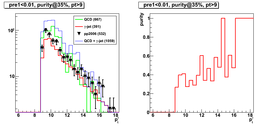
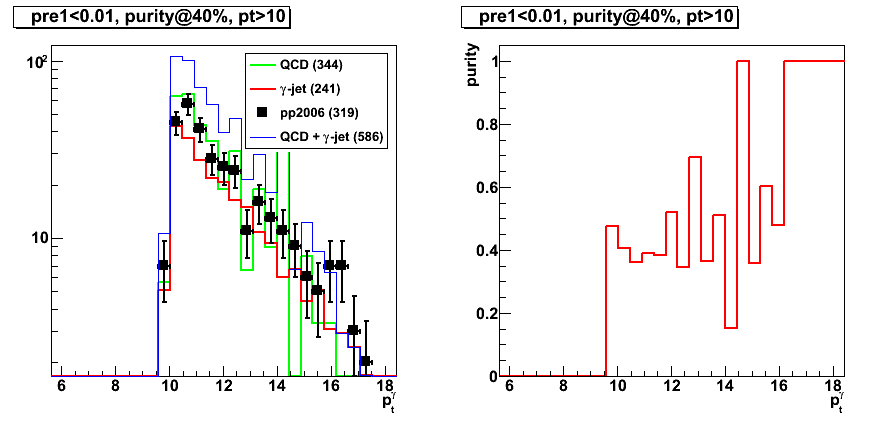
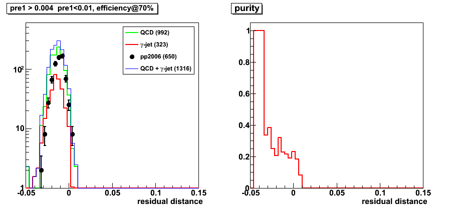
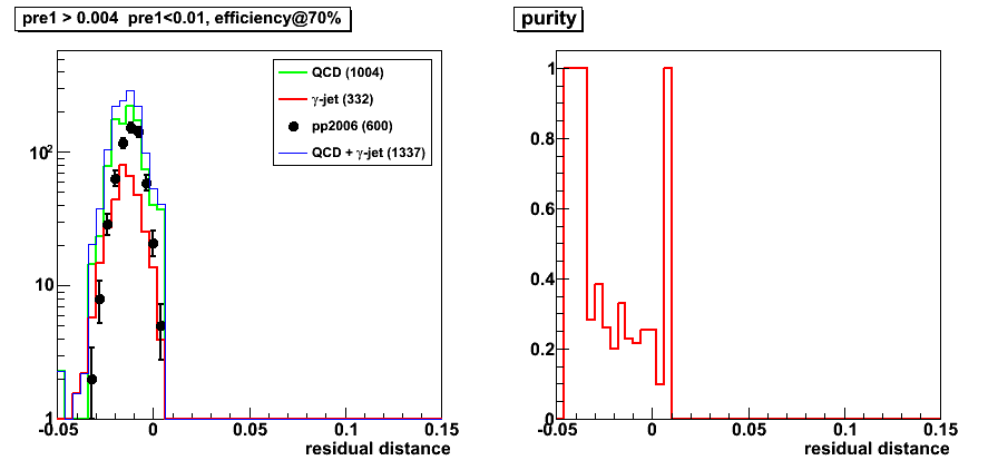
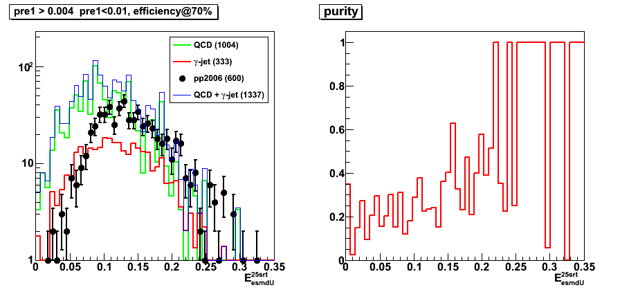
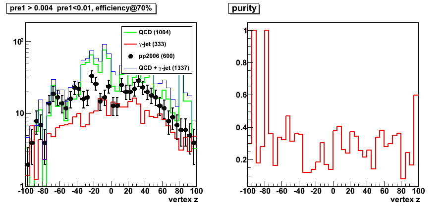
2009.05.06 Applying cuts on LDA: request minimum purity or efficiency
Cut optimization with Fisher's LDA classifier
For this post LDA input parameters Set4 has been used
LDA for various pre-shower bins is trained independetly,
and later results with pre-shower1<0.01 are combined.
There are a set of plots for various photon pt cuts (pt> 7, 8, 9 10 GeV)
and with different selection of cutoff for LDA
(either based on purity or efficiency).
Number in brackets shows the total yield for the sample.
Link to all plots (16 total) as a single pdf file
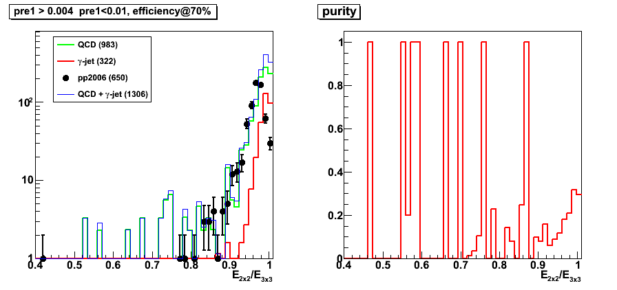
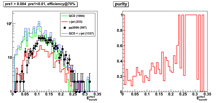
pt > 7GeV
Figure 1: pt > 7GeV, efficiency@70
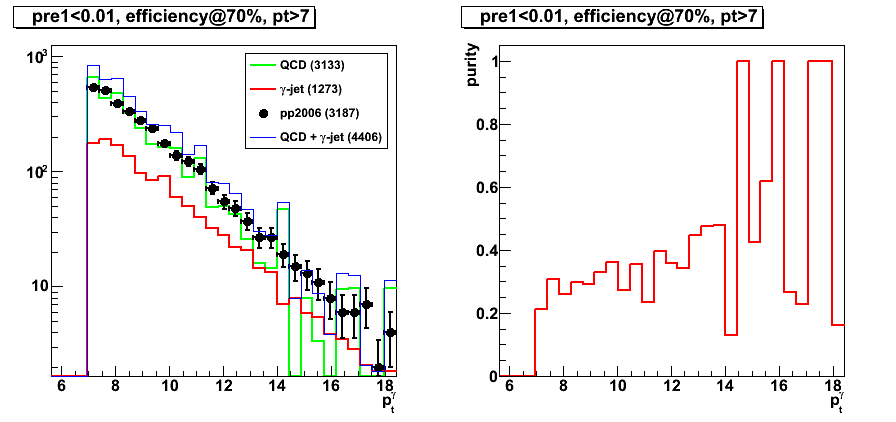
Figure 2: pt > 7GeV, purity@35
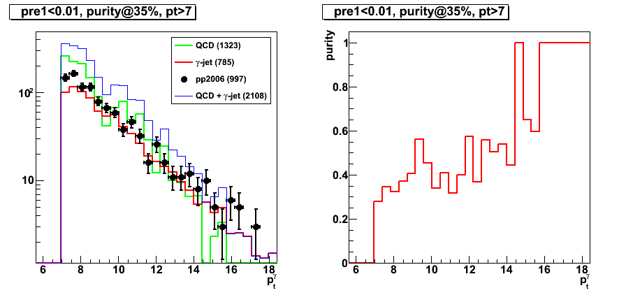
Figure 3: pt > 7GeV, purity@40
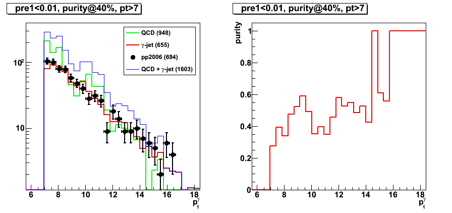
Figure 4: pt > 7GeV, purity@25 (Note: very similar to results with efficiency@70)
pt > 9GeV
Figure 5: pt > 9GeV, efficiency@70
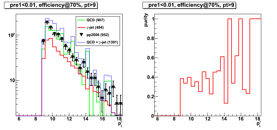
Figure 6: pt > 9GeV, purity@35
pt > 10GeV
Figure 7: pt > 10GeV, efficiency@70
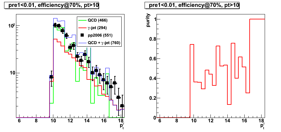
Figure 8: pt > 10GeV, purity@40
2009.05.07 Photon-jets analysis with the Endcap Calorimeter
Photon-jets with the Endcap Calorimeter
(analysis status update for Spin PWG)
Slides in pdf format:
2009.05.12 Variable distributions after LDA at 70% efficiency
Cut optimization with Fisher's LDA classifier
For this post LDA results with Set1 and Set2 has been used
Note, that LDA for various pre-shower bins is trained independetly
pdf-links with results for pre1=0 and pre2=0 (pre-shower bin 1):
- before LDA cut (figures are not sorted)
- after LDA cut @70% efficiency for Set 2 (figures are not sorted)
Figures below are for 0.004<pre-shower1<0.01 (pre-shower bin 4).
Photon pt cut: pt> 7, pre-shower bin: 0.004 < pre1 < 0.01
LDA cut with efficiency @ 70%
Set1 vs. Set2
What is added in Set2 compared to Set1:
smaller cluster size information (r2x1, r2x2), post-shower energy
Figure 1: r2x1
before LDA cut
LDA cut for Set1

LDA cut for Set2
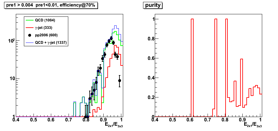
Figure 2: r2x2
before LDA cut

LDA cut for Set1
LDA cut for Set2
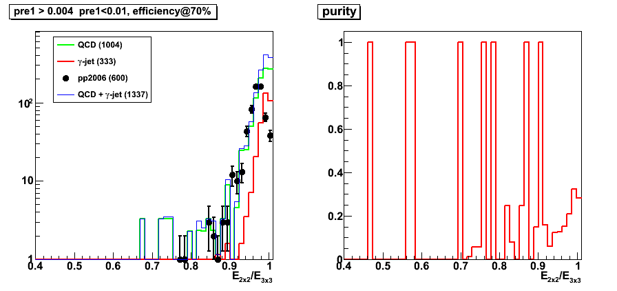
Figure 3: r3x3
before LDA cut
LDA cut for Set1

LDA cut for Set2
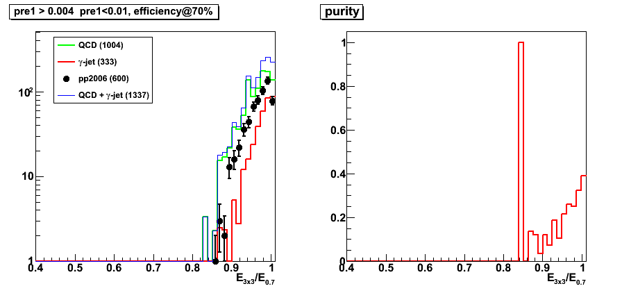
Figure 4: Residual distance
before LDA cut
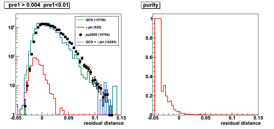
LDA cut for Set1
LDA cut for Set2
Other variables with LDA Set2 cut
Note: Only plos for LDA cut @70 efficiency for Set2 are shown
Figure : number of charge particles around photon

Figure 5: number of EEMC tower around photon
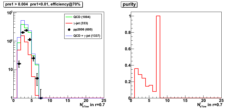
Figure 6: number of BEMC tower around photon
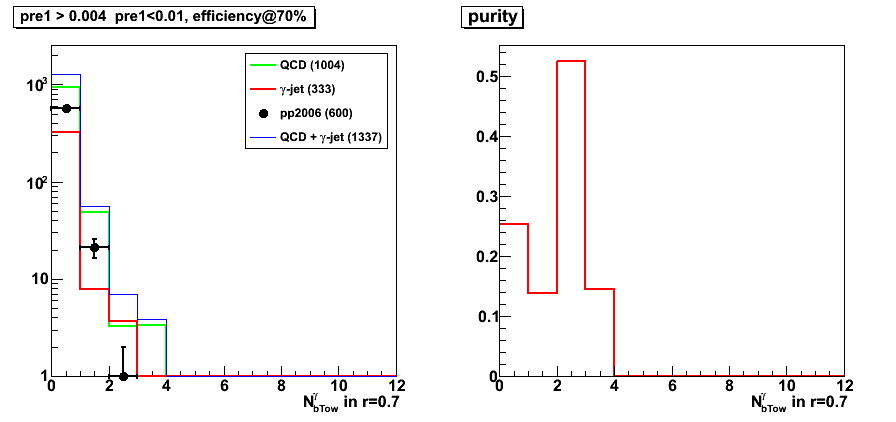
Figure 7: photon-jet pt balance
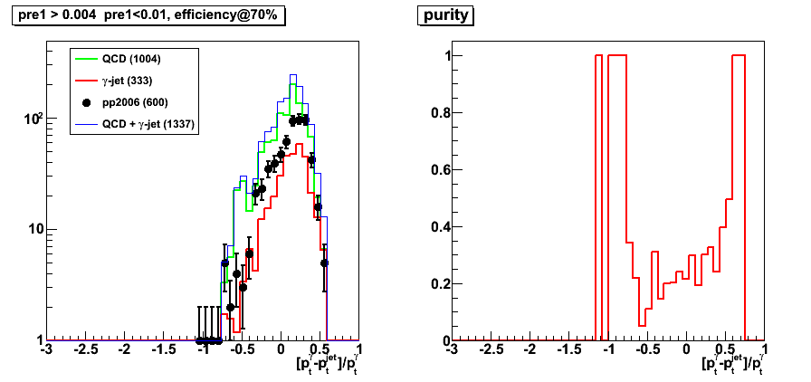
Figure 8: SMD energy in 5 centrapl strips
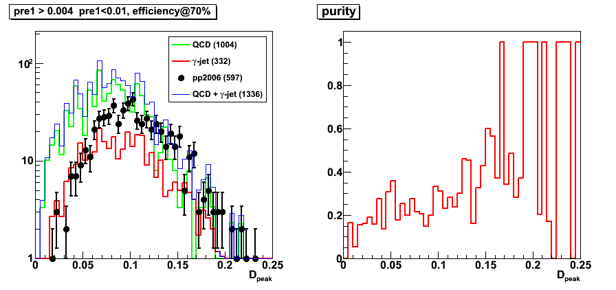
Figure 9: SMD energy in 25 central strips: u and v plane separately (plot for V plane)
Figure 10: 2x1 cluster energy
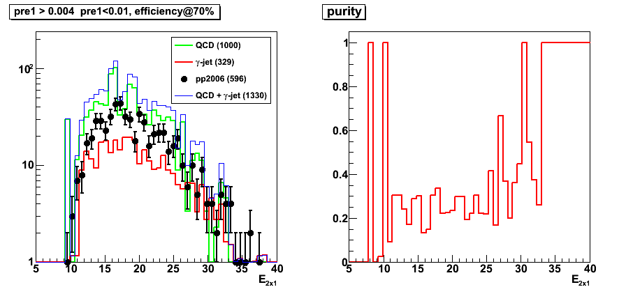
Figure 11: 2x2 cluster energy
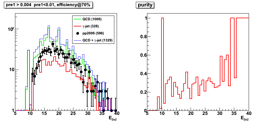
Figure 12: 3x3 cluster energy

Figure 13: tower energy in r=0.7 radius
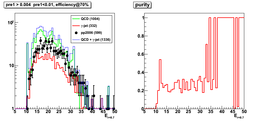
Figure 14: 3x3 pre-shower1 energy

Figure 15: 3x3 pre-shower2 energy
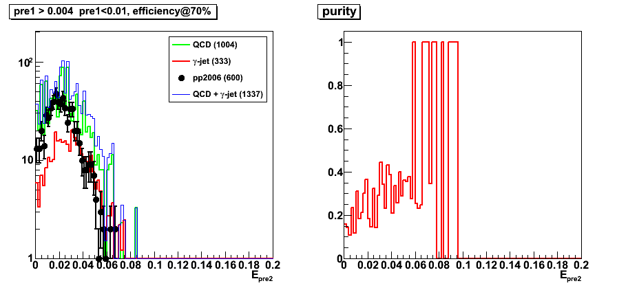
Figure 16: 3x3 post-shower energy

Figure 17: photon pt

Figure 18: jet pt
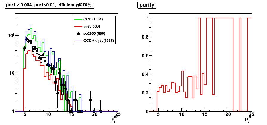
Figure 19: z vertex
2009.05.31 CIPANP 2009 photon-jet presentation
CIPANP 2009 presentation on photon-jet study
Title:
"Photon-jet coincidence measurements
in polarized pp collisions at sqrt{s}=200GeV
with the STAR Endcap Calorimeter"
- Presentation in pdf format
- Older versions: 0, 1, 2 3, 4, 5, open office file: odp
- Submitted abstract
- Conference link: CIPANP 2009
06 Jun
June 2009 posts
2009.06.22 CIPANP 2009 photon-jet proceedings
CIPANP 2009 proceedings on photon-jet study
Title:
"Photon-jet coincidence measurements
in polarized pp collisions at sqrt{s}=200 GeV
with the STAR Endcap Calorimeter"
- Proceedings: latest version
Older versions: 01 02 03 04 05 - Presentation
- Submitted abstract
- Conference link: CIPANP 2009
07 Jul
July 2009 posts
2009.07.21 EEMC tower response in Monte-Carlo
Data set and cuts:
- gamma-jet filtered Monte-Carlo
- Di-jet events from the jet finder (jets threshold: 3.5 GeV)
- parton pt bin 3-4 GeV (see pt_gamma distributions for various parton pt bins)
- Thrown photon pseudo-rapidity: eta in [1-2] range
- Requires to reconstruct photon candidate in the EEMC
Figure 1: Average ratio: pt_true / (pt_reco/1.3) vs. pt_reco (GeV/c)
- Introduce 1.3 factor here to remove the effect of the fudge factor in slow simulator
- Since a limited partonic pt range (3-4 GeV) is used for this study,
there is an "artificial" increase of the plotted ratio in pt_gamma > 6 GeV range - Fig. 1 reflects similar features (over a limited pt range) as those found by Hal
in his single photon study (see slide 6 of SimulationStudies.ppt presentation)
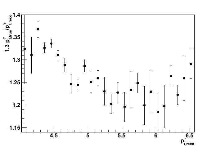
Figure 2:
Average momentum difference: pt_true - (pt_reco/1.3) vs. pt_reco (GeV/c)
- Fig. 2 shows that on average in GEANT Monte-Carlo we miss ~1GeV independent on the photon pt.
EEMC detector response can be still linear even if the ratio in Fig. 1 is not flat. - Usage of fixed 1.3 (or others, like 1.25) fudge factors are not justified.
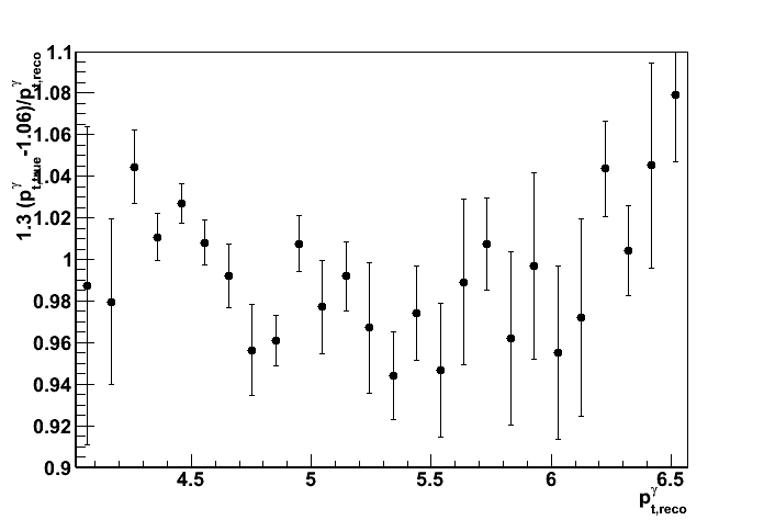
- It seems that using pt-dependent fudge factor (like it is done in this Jason's study)
is also unjustified, since the same effects (flat ratio of pt_reco/pt_true ~ 1)
can be reached by subtracting 1 GeV from the cluster energy (See Fig. 3).
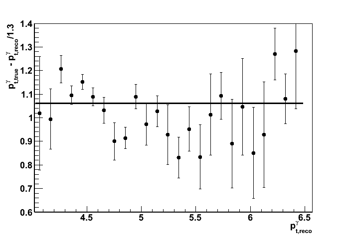
Figure 3: Average ratio: (pt_true -1.06) (pt_reco/1.3) vs. pt_reco (GeV/c)
Similar to Fig. 1, but with the true photon pt reduced by 1.06 GeV
Resulting true/reco pt ratio is flat in 4-6 GeV range.
Before further pursuing our efforts in tuning the tower energy response in the Monte-Carlo,
needs to address the observed energy loss difference in the fisrt layer of the BEMC/EEMC detector.
See Jason's blog post from 2009.07.16 for more details:
Comparison muon energy deposit in the 1st BEMC/EEMC layers
08 Aug
August 2009 posts
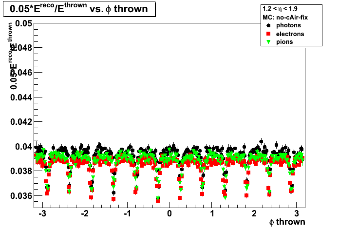
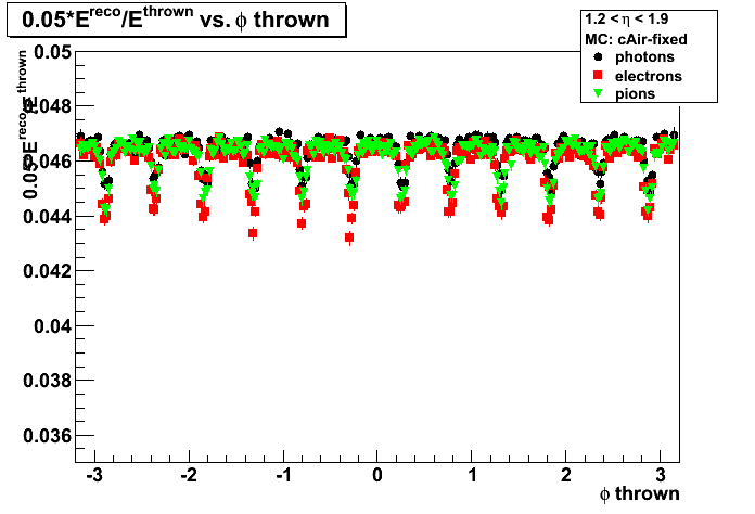
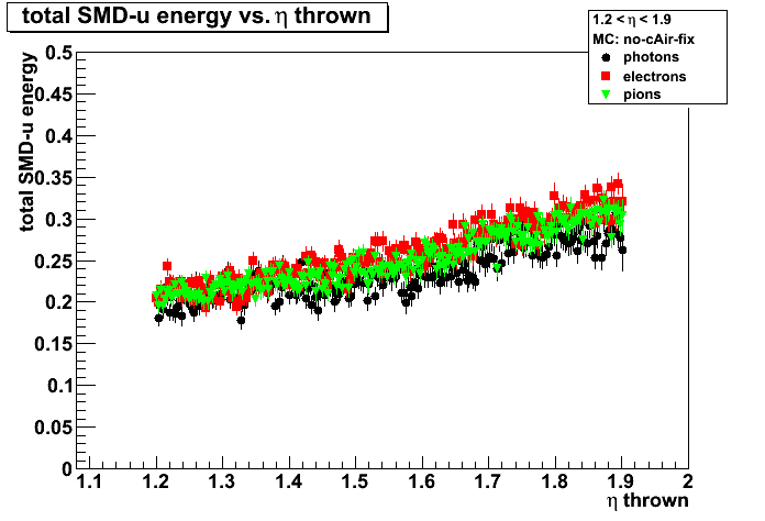
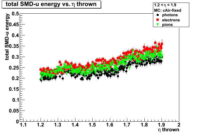
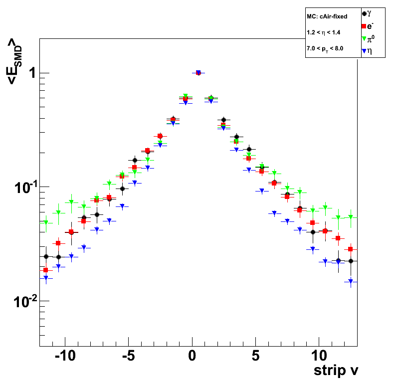
2009.08.24 Test of corrected EEMC geometry
Test of corrected EEMC geometry (bug 1618)
Monte-Carlo setup:
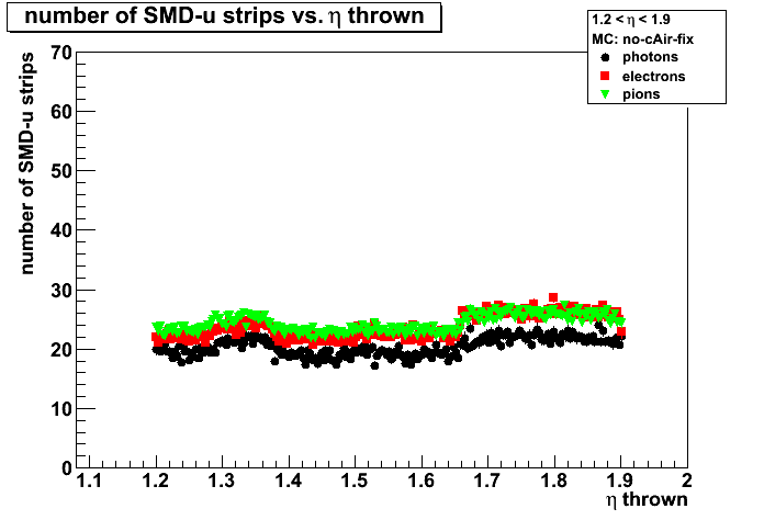
- One particle per event (photons, electrons, and pions)
- Full STAR 2006 geometry.
In Kumac file: detp geom y2006g; gexec $STAR_LIB/geometry.so - Flat in eta (1.08-2.0), phi (0,2pi), and pt (3-30 GeV)
- Using A2Emaker to get reconstructed Tower/SMD energy (no EEMC SlowSimulator in chain)
what assumes fixed sampling fraction of 0.05 (5%)
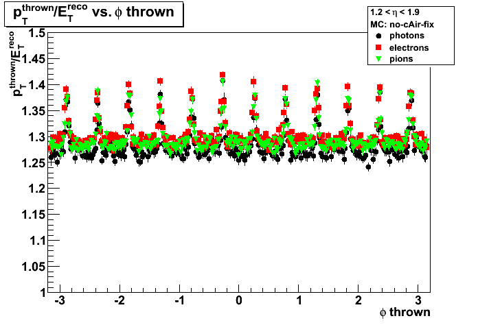
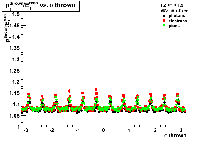
Some definitions:
- Et correction factor : average p_T^thrown / E_T^{reco}.
E_T^{reco} is the total energy in the Endcap Calorimeter (from A2Emaker) - Sampling fraction: average 0.05 * Energy^{reco} / Energy^thrown.
- SMD energy: average energy in all strips fired (u-plane used for this post)
- Number of SMD strips fired: average total number of strips fired (u-plane used for this post)
Notations used in the plots:
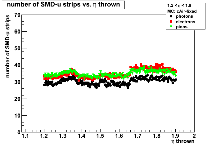
- Left plots: no cAir fix
- Right plots: cAir-fixed
- Photons: black
- Electrons: red
- Pions: green
Et correction
Note: compare "Left" plots with Brians old results
Figure 1a: Et correction factor vs. pt thrown
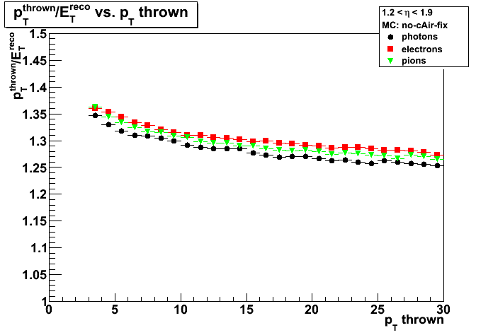
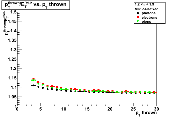
Figure 1b: Et correction factor vs. eta thrown


Figure 1c: Et correction factor vs. phi thrown
Sampling fraction
Note: compare "Right" plots with Jason results with EEMC only geometry
Figure 2a: Sampling fraction vs. pt thrown
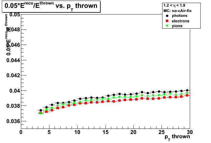
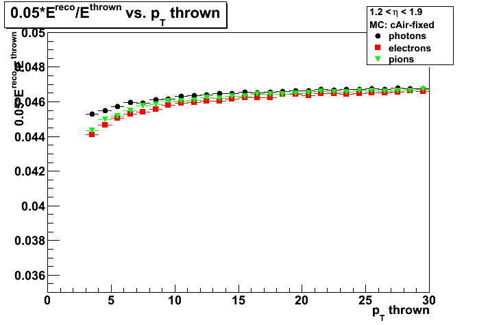
Figure 2b: Sampling fraction vs. energy thrown
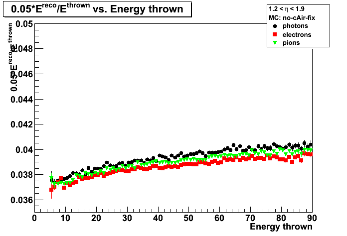
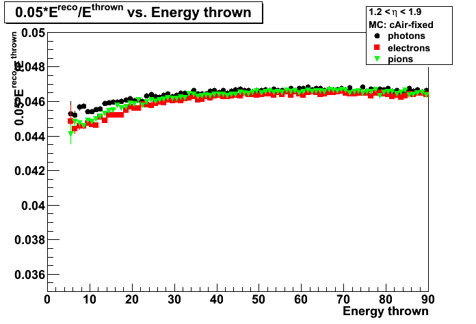
Figure 2c: Sampling fraction vs. eta thrown

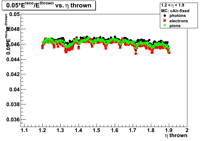
Figure 2d: Sampling fraction vs. phi thrown
SMD energy
Figure 3a: SMD energy vs. energy thrown


Figure 3b: SMD energy vs. eta thrown
Number of SMD strips fired
Figure 4a: Number of SMD strips fired vs. energy thrown

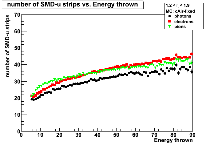
Figure 4b: Number of SMD strips fired vs. eta thrown
2009.08.25 Test of corrected EEMC geometry: shower shapes
Test of corrected EEMC geometry (bug 1618)
Monte-Carlo setup is desribed here
- One particle per event (photons, electrons, and pions)
- Full STAR 2006 geometry.
In Kumac file: detp geom y2006g; gexec $STAR_LIB/geometry.so - Flat in eta (1.08-2.0), phi (0,2pi), and pt (3-30 GeV)
- Using A2Emaker to get reconstructed Tower/SMD energy (no EEMC SlowSimulator in chain)
what assumes fixed sampling fraction of 0.05 (5%) - Vertex z=0
- ~50K/per particle type
- Non-zero energy: 3 sigma above pedestal
Figure 1:Single photon shower shape before (red) and after (black) EEMC cAir bug fixed
pt=7-8GeV, eta=1.2-1.4 (left), eta=1.6-1.8 (right)
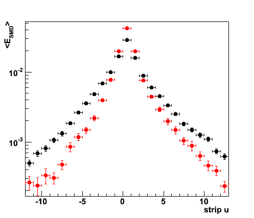
Figure 2: Single photon shower shape vs. data
Monte-Carlo: pt=7-10GeV, eta=1.6-1.8
data: no pre-shower1,2; pt_photon>7, pt_jet>5. no eta cuts.
(see Fig. 1 from here for other pre-shower conditions)
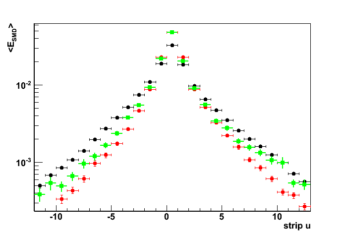
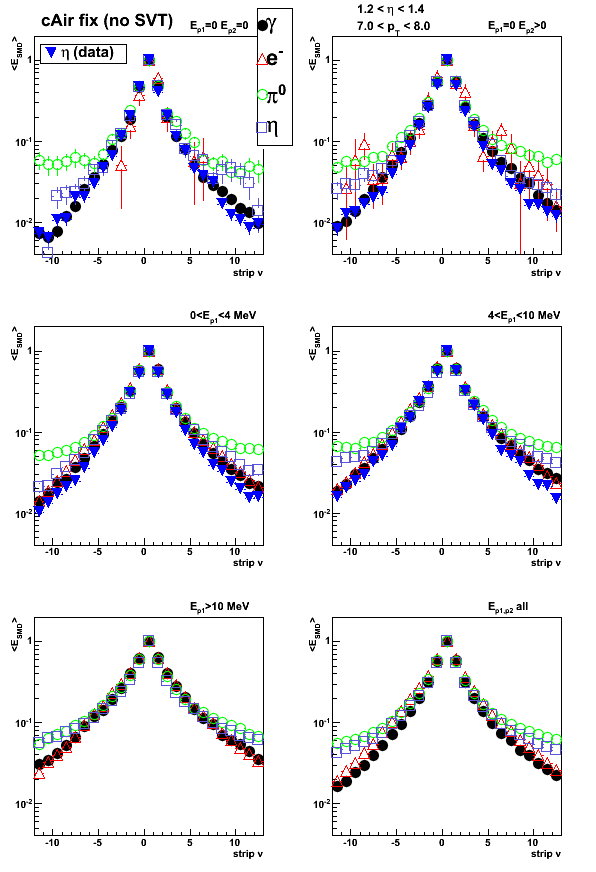
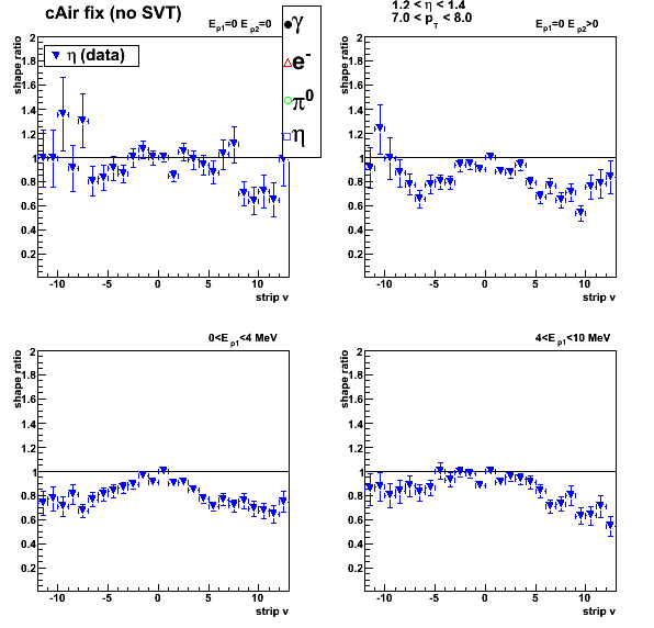
2009.08.27 fixed EEMC geometry: pre-shower sorted shower shapes & eta-meson comparison
Test of corrected EEMC geometry: shower shapes (bug 1618)
Monte-Carlo setup is desribed here
- One particle per event (photons, electrons, and pions)
- Full STAR 2006 geometry.
In Kumac file: detp geom y2006g; gexec $STAR_LIB/geometry.so - Flat in eta (1.08-2.0), phi (0,2pi), and pt (3-30 GeV)
- Using A2Emaker to get reconstructed Tower/SMD energy (no EEMC SlowSimulator in chain)
what assumes fixed sampling fraction of 0.05 (5%) - Vertex z=0
- ~50K/per particle type
- Non-zero energy: 3 sigma above pedestal
Color coding:
- Black - photon (single particle/event MC)
- Red - electron (single particle/event MC)
- Green - neutral pion (single particle/event MC)
- Blue - photons from eta-meson decay (real data)
Single particle shower shape before (left) and after (right) EEMC cAir bug fixed
Single particle kinematic cuts: pt=7-8GeV, eta=1.2-1.4
Eta-meson shower shapes (blue) taken from Fig. 1 from here of this post
All shapes are normalized to 1 at peak (central strip).
Figure 1: Pre-shower bin 0: E_pre1=0; E_pre2=0
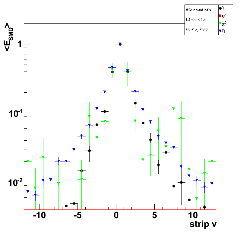
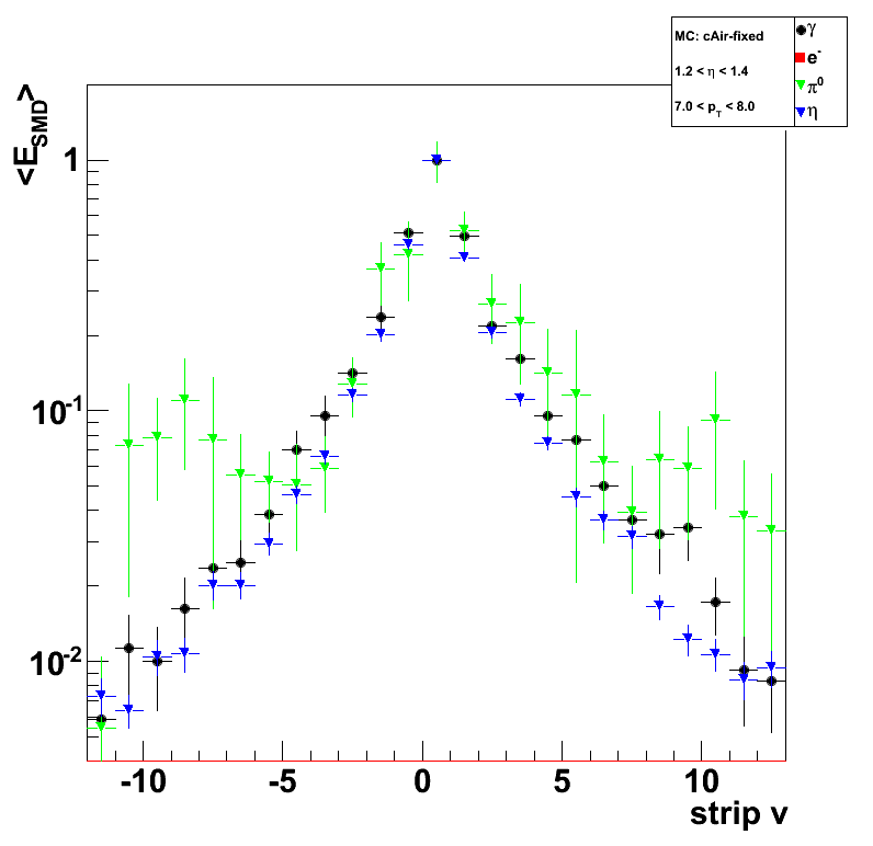
Figure 2: Pre-shower bin 1: E_pre1=0; E_pre2>0
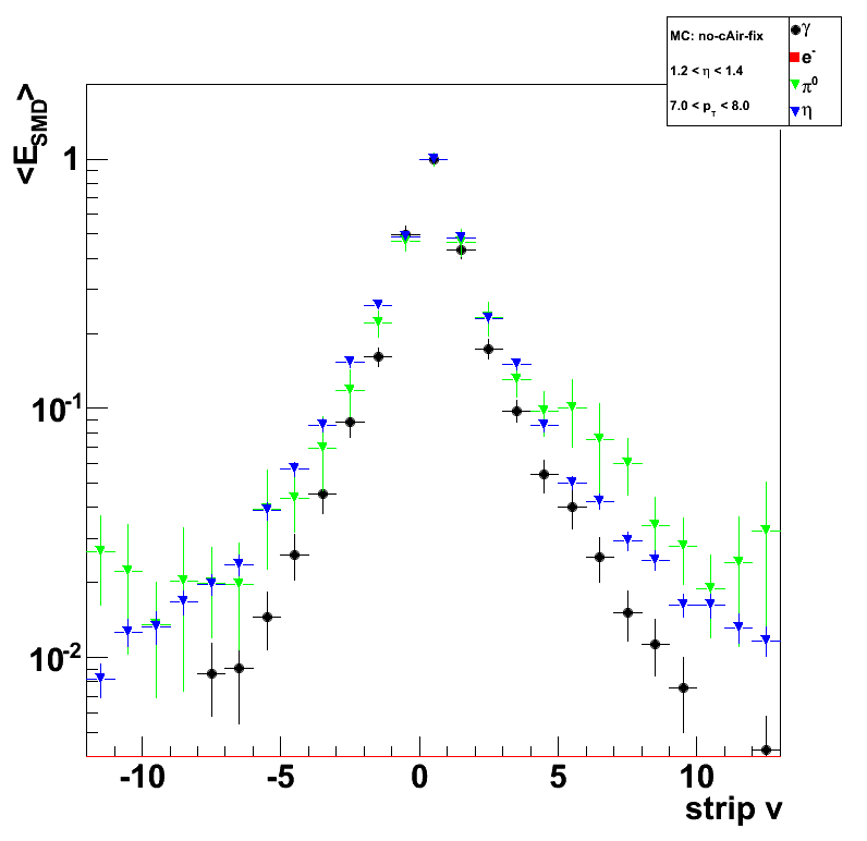
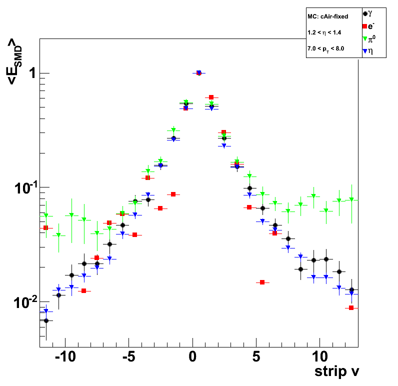
Figure 3: Pre-shower bin 2: E_pre1>0; E_pre1<0.004

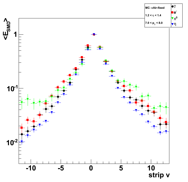
Figure 4: Pre-shower bin 3: E_pre1>0.004; E_pre1<0.01

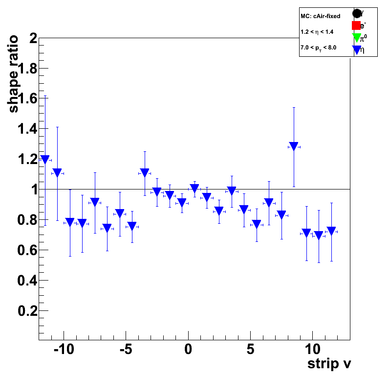
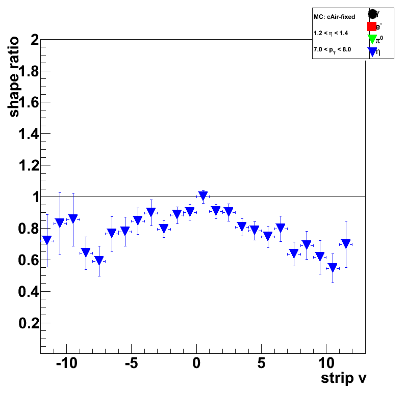
Shower shape ratios
Results only for corrected EEMC geometry
All shapes are divided by MC single-photon shower shape.
Figure 5a: Pre-shower bin 0: E_pre1=0; E_pre2=0
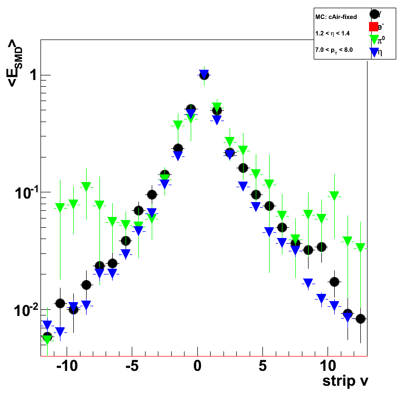
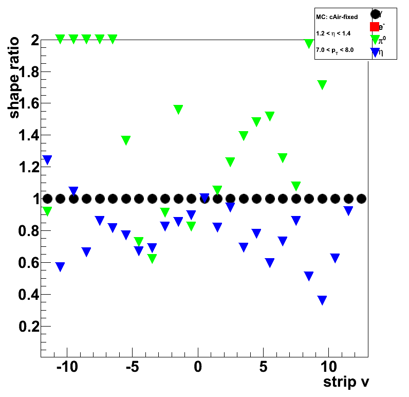
Figure 5b: Pre-shower bin 1: E_pre1=0; E_pre2>0
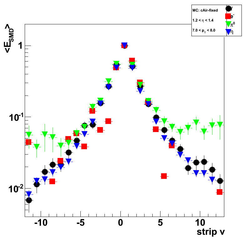
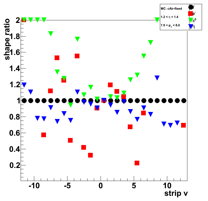
Figure 5c: Pre-shower bin 2: E_pre1>0; E_pre1<0.004
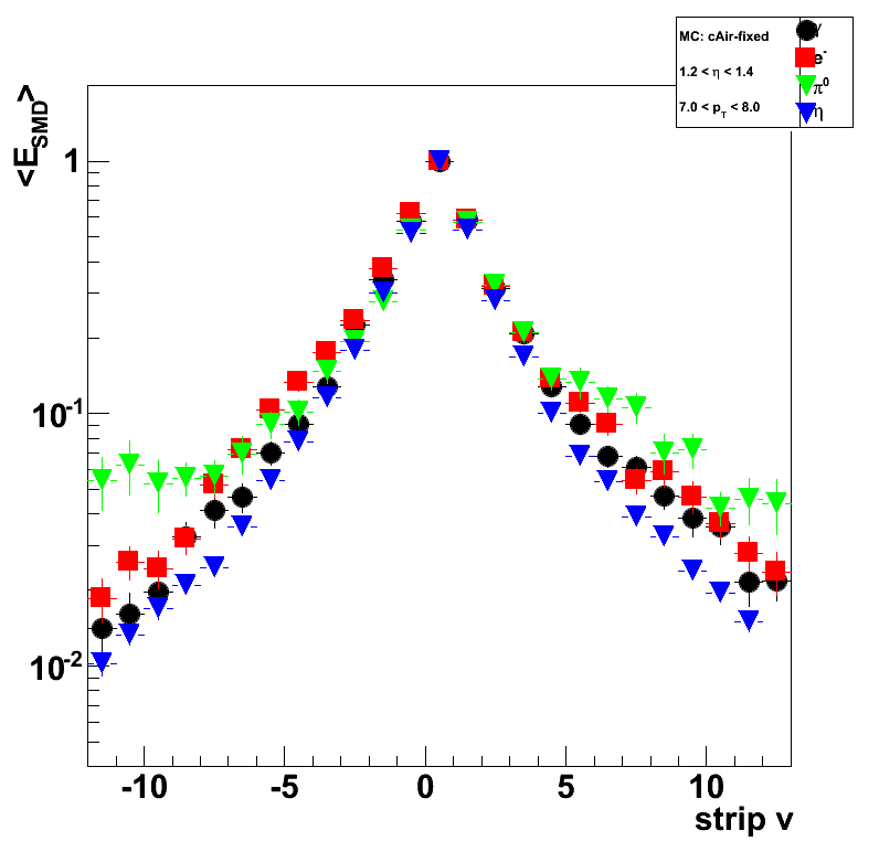
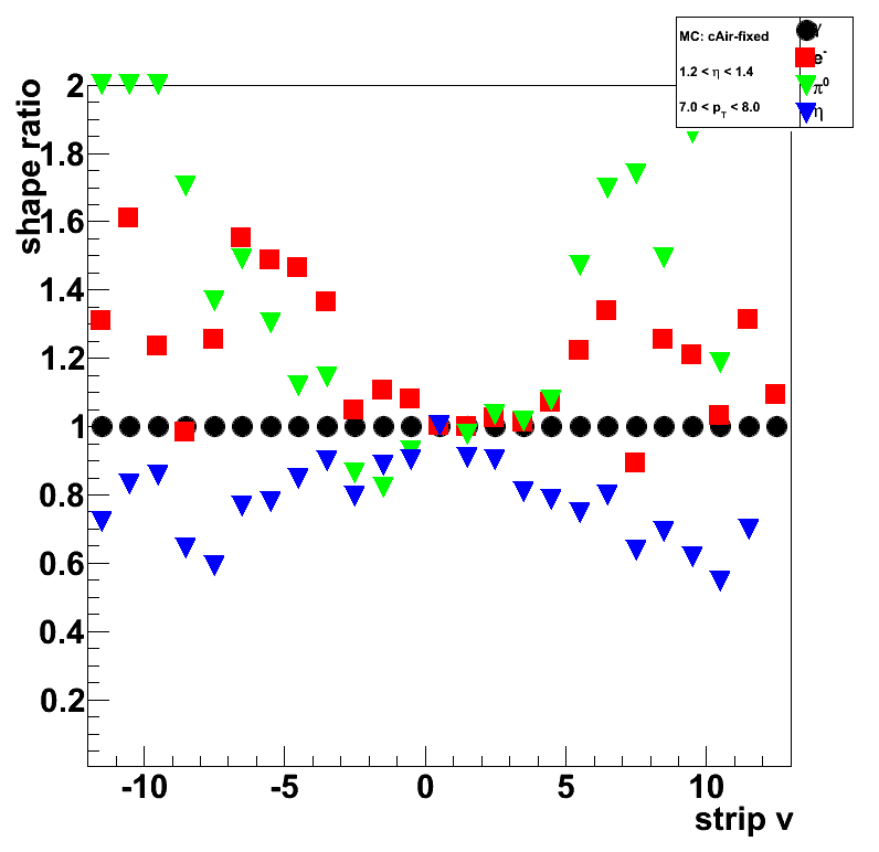
Figure 5d: Pre-shower bin 3: E_pre1>0.004; E_pre1<0.01
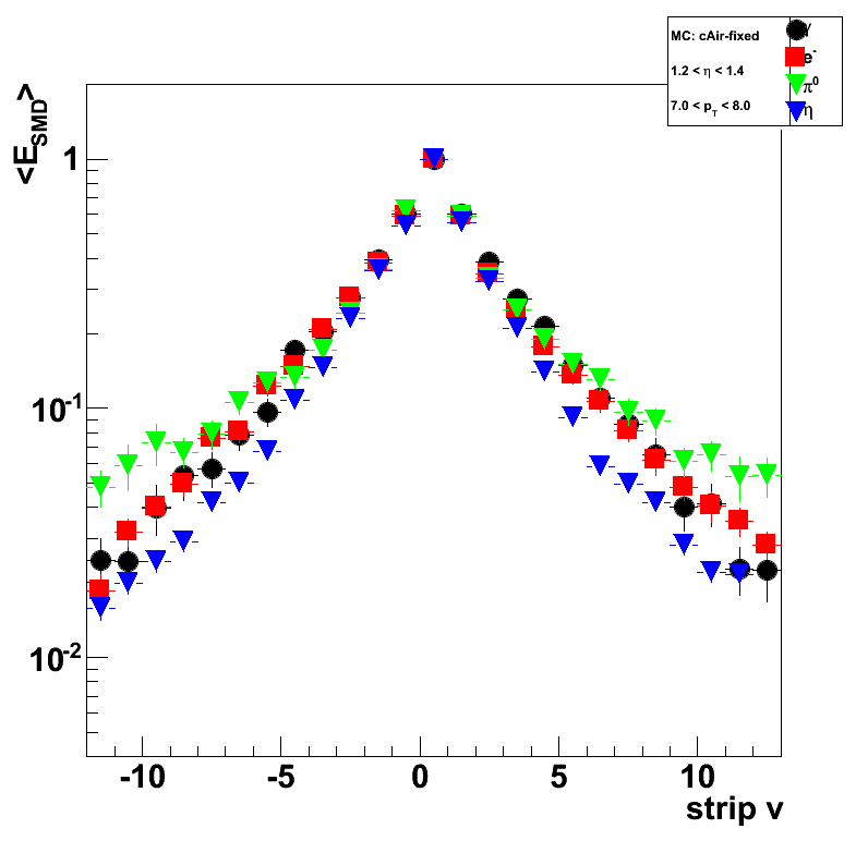
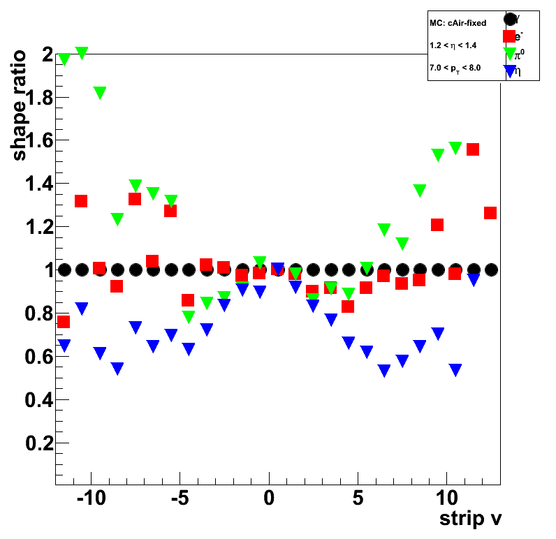
Figure 6: Single photon to eta-meson shape ratios only (with error bars):
Pre-shower bins 0 (upper-left),1 (upper-right),2 (lower-left), and 3 (lower-right)


Extracting gamma-jet cross section at forward rapidity from pp@200GeV collisions
Analysis overview
- Data samples, event selection, luminosity determination
- Isolating photon-jet events
- Transverse shower shape analysis
- Isolation cuts
- Cut optimization
- Trigger effects study
- Data to Monte-Carlo comparison/normalization and raw yields
- Acceptance/efficiency corrections
- Corrected yields
- Background subtraction
- Systematic uncertainties
- Comparison with theory
Data samples, event selection, luminosity determination
Real data, and signal/background Monte-Carlo samples:
-
pp@200GeV collisions, STAR produnctionLong.
Trigger: eemc-http-mb-L2gamma [id:137641] (L ~ 3.164 pb^1) -
Pythia prompt photon (signal) Monte-Carlo sample.
Filtered Prompt Photon p6410EemcGammaFilter.
Partonic pt range 2-25 GeV. -
Pythia 2->2 hard QCD processes (background) Monte-Carlo sample.
Filtered QCD p6410EemcGammaFilter.
Partonic pt range 2-25 GeV.
Isolating photon-jet events
- Shower shape analysis
- Isolation cuts
- Energy clustering (2x1 vs. 2x2 vs. 3x3, cluster energy vs. rapidity)
- Charge particle veto
- photon and jet pt balance
- Tower multiplicity
- Cut optimization with LDA.
Input variables (list can be expanded):- Energy fraction in 3x3 cluster within a r=0.7 radius, E_3x3/E_0.7
- Photon-jet pt balance, [pt_gamma-pt_jet]/pt_gamma
- Number of charge tracks within r=0.7 around gamma candidate
- Number of Endcap towers fired within r=0.7 around gamma candidate
- Number of Barrel towers fired within r=0.7 around gamma candidate
- Shower shape analysis: distance to 80% cut line
- Energy fraction in E_2x1 and E_2x2 witin E_3x3
- Energy in post-shower layer under 3x3 tower patch
- Tower energy in 3x3 patch
- SMD-u/v energy in 25 central strips
- SMD-u/v peak energy (in 5 central strips)
Trigger effects study
No studies yet
- Trigger effects vs pt
- Trigger effects vs eta
- What else?
Data to Monte-Carlo comparison/normalization and raw yields
- Overall data to MC normalization based on vertex z distribution
- Data to MC comparison of raw yield in various detector subsystems
- Uncorrected yields optimized with different efficiency/purity
Acceptance/efficiency corrections
No studies yet
- What needs to be studied for acceptance/efficiency effects?
- Converting reconstructed photon (jet) energy/momentum to the true one
- Reconstruction efficiency vs. rapidity, pt, etc
Corrected yields
No studies yet
- Produce acceptance/efficiency corrected yields
Background subtraction
No studies yet
- Statistical background subtraction based on Pythia+GEANT Monte-Carlo
- Estimate systematic uncertainties due to background subtraction
Systematic uncertainties
No studies yet
- Calorimeter energy resolution
- Trigger bias
- Other effects
Comparison with theory
No comparison yet
- Request for pQCD calculations at forward rapidity
09 Sep
September 2009 posts
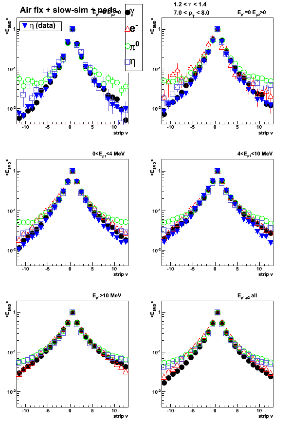
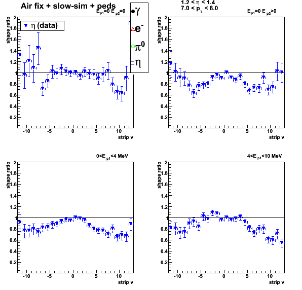
2009.09.04 Test of corrected EEMC geometry: SVT, slow-simulator on/off, pre-shower migration
Test of corrected EEMC geometry: shower shapes (bug 1618)
Monte-Carlo setup:
- One particle per event (photons, electrons, pions, and eta-meson)
- Full STAR 2006 geometry (with/without SVT)
In Kumac file: detp geom y2006g; gexec $STAR_LIB/geometry.so (remove SVT with SVTT_OFF option) - Throw particles flat in eta (1.08, 2.0), phi (0, 2pi), and pt (6-10 GeV)
- Using A2Emaker to get reconstructed Tower/SMD energy
(with/without EEMC SlowSimulator in chain) - Vertex z=0
- ~50K/per particle type
- Non-zero energy: 3 sigma above pedestal
Color coding:
- Photon (single particle MC)
- Electron (single particle MC)
- Neutral pion (single particle MC)
- Eta-meson (single particle MC)
- Eta-meson [pp2006 data] (single photons from eta-meson decay)
Pre-shower bins:
- Ep1 = 0, Ep2 = 0 (no energy in both EEMC pre-shower layers)
- Ep1 = 0, Ep2 > 0
- 0 < Ep1 < 4 MeV
- 4 < Ep1 < 10 MeV
- Ep1 > 10 MeV
- All pre-shower bins combined
Ep1/Ep2 is the energy deposited in the 1st/2nd EEMC pre-shower layer.
For a single particle MC it is a sum over
all pre-shower tiles in the EEMC with energy of 3 sigma above pedestal.
For eta-meson from pp2006 data the sum is over 3x3 tower patch
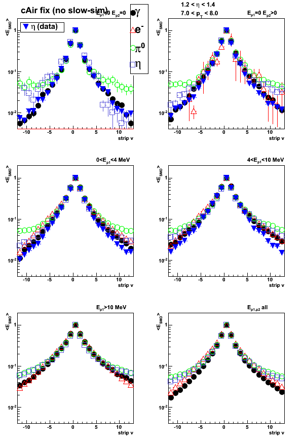
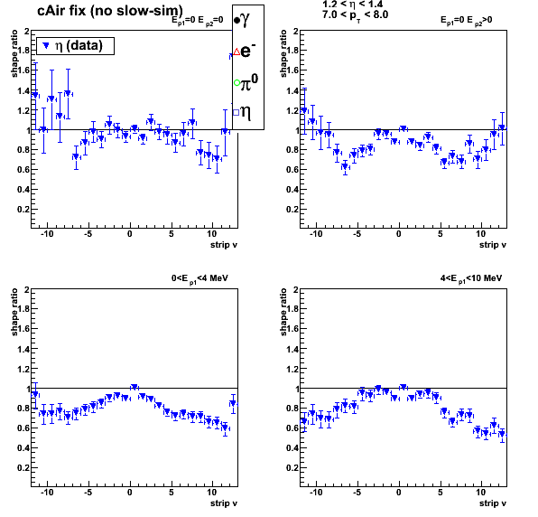
Shower shapes
Single particle kinematic cuts: pt=7-8GeV, eta=1.2-1.4
Eta-meson shower shapes (blue) taken from Fig. 1 from here of this post
All shapes are normalized to 1 at peak (central strip)
Figure 1: Shower shape sorted by pre-shower conditions.
cAir-Fixed EEMC geometry (NO slow simulator, WITH SVT)
Ratio plot
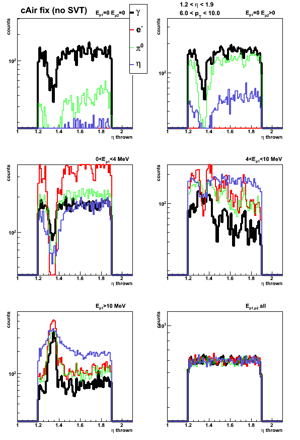
Figure 2: Shower shape sorted by pre-shower conditions.
cAir-Fixed EEMC geometry (NO slow simulator, NO SVT)
Ratio plot
Figure 3: Shower shape sorted by pre-shower conditions.
cAir-Fixed EEMC geometry (WITH slow simulator, WITH SVT)
Ratio plot
Figure 4: Shower shape sorted by pre-shower conditions.
Old cAir-bug EEMC geometry (NO slow simulator, WITH SVT)
Click here to see the plot
Pre-shower migration with/without SVT
Starting with a fixed (50K events) for each type of particle.
Change in number of counts for a given pre-shower bin
with different detector configuration shows pre-shower migration
Figure 5: Pre-shower migration.
cAir-Fixed EEMC geometry (WITH SVT)
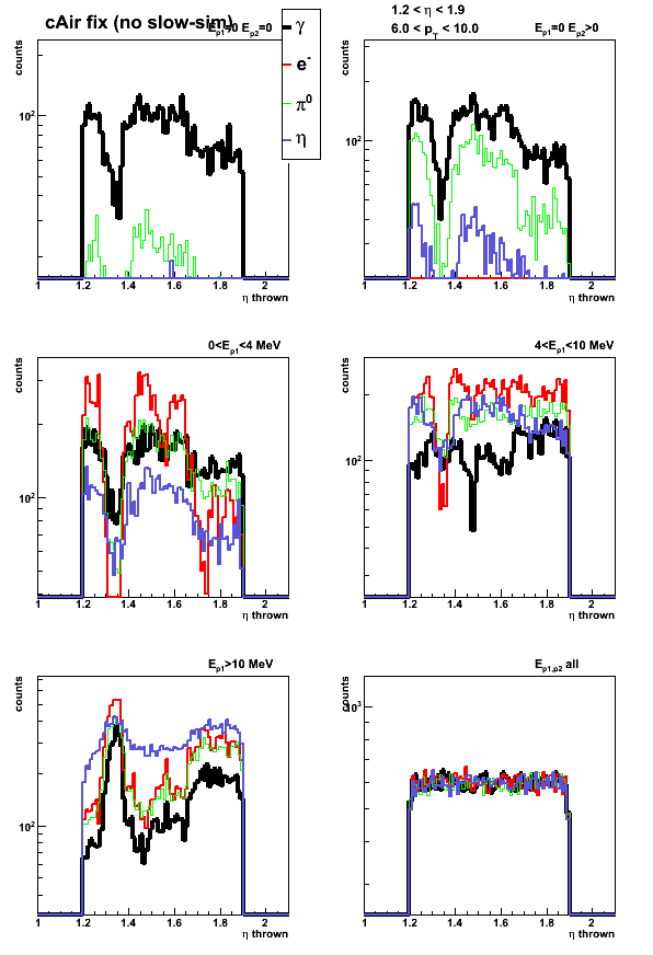
Figure 6: Pre-shower migration.
cAir-Fixed EEMC geometry (WITHOUT SVT)
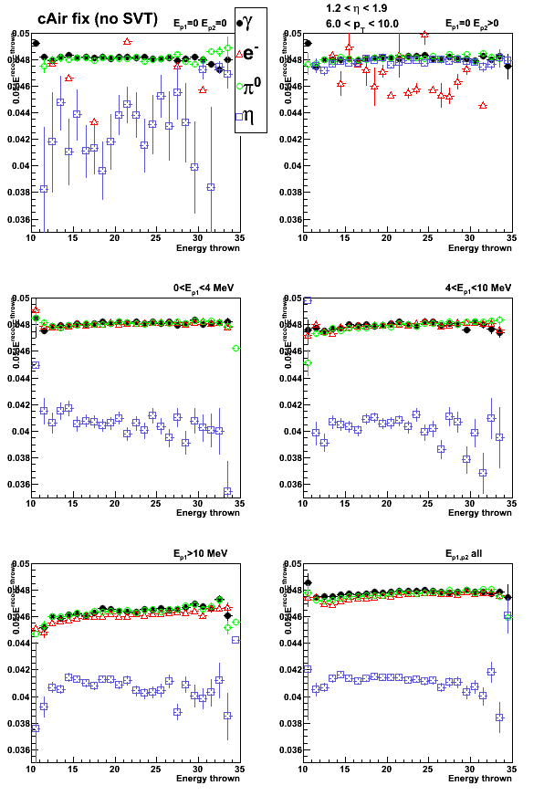
Sampling fraction with/without Slow-simulator
Figure 7: Sampling fraction (0.05 E_reco / E_thrown).
cAir-Fixed EEMC geometry (WITHOUT Slow-simulator)

Figure 8: Sampling fraction (0.05 E_reco / E_thrown).
cAir-Fixed EEMC geometry (WITH Slow-simulator)
Slow simulator introduce some non-linearity in the sampling fraction

Figure 9: Sampling fraction (0.05 E_reco / E_thrown).
cAir-Fixed EEMC geometry (WITHOUT SVT, WITHOUT Slow-simulator)
Click here to see the plot
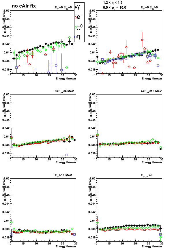
Figure 10: Sampling fraction (0.05 E_reco / E_thrown).
Old cAir-bug EEMC geometry (NO slow simulator, WITH SVT)
Click here to see the plot
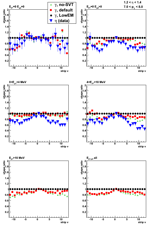
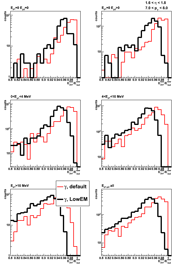
2009.09.11 Test of corrected EEMC geometry: LOW_EM cuts
Test of corrected EEMC geometry: SVT and LOW_EM cuts
Monte-Carlo setup:
- One particle per event (only photons in this post)
- Full STAR 2006 geometry (with/without SVT, LOW_EM cuts)
In Kumac file: detp geom y2006g; gexec $STAR_LIB/geometry.so (vary SVTT_OFF, LOW_EM)
LOW_EM cut definition is given at the end of this page - Throw particles flat in eta (1.2, 1.9), phi (0, 2pi), and pt (6-10 GeV)
- Using A2Emaker to get reconstructed Tower/SMD energy
(this post: no EEMC SlowSimulator) - Vertex z=0
- ~50K/per iteration
- Non-zero energy: 3 sigma above pedestal
Color coding:
- SVT, LOW_EM marked in legend as LowEM (single photon MC)
- STV, no-LOW_EM marked in legend as default (single photon MC)
- no-SVT, no-LOW_EM marked in legend as no-SVT (single photon MC)
- photon-jet candidates [pp2006] (used data points from this post)
- photons from eta-meson [pp2006]
Pre-shower bins:
- Ep1 = Ep2 = 0 (no energy in both EEMC pre-shower layers)
- Ep1 = 0, Ep2 > 0
- 0 < Ep1 < 4 MeV
- 4 < Ep1 < 10 MeV
- Ep1 > 10 MeV
- All pre-shower bins combined
Note: Ep1/Ep2 is the energy deposited in the 1st/2nd EEMC pre-shower layer.
For a single photon MC it is a sum over
all pre-shower tiles in the EEMC with energy of 3 sigma above pedestal.
For eta-meson/gamma-jet candidates from pp2006 data the sum is over 3x3 tower patch
Shower shapes
Single particle kinematic cuts: pt=7-8GeV, eta=1.2-1.4
Eta-meson shower shapes (blue) taken from Fig. 1 from here of this post
All shapes are normalized to 1 at peak (central strip)
Figure 1: Shower shape sorted by pre-shower conditions.

Figure 2: Shower shape ratio. All shapes in Fig. 1 are divided by single photon shape
for "SVT+LOW_EM" configuration (black circles in Fig. 1)
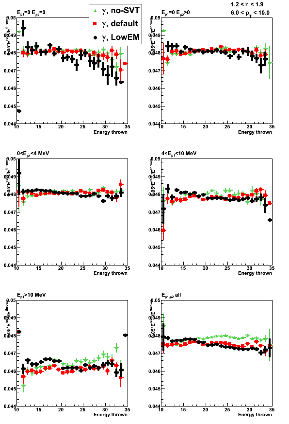
Sampling fraction
Figure 3: Sampling fraction (0.05 * E_reco/ E_thrown)
Pre/post-shower energy and migration
Figure 4: Pre-shower1 energy (all tiles)

Figure 5: Pre-shower2 energy (all tiles)

Figure 6: Post-shower energy (all tiles)

Figure 7: Pre-shower bin photon migration

Tower energy profile
Figure 8a: Energy ratio in 2x1 to 3x3 cluster
For the first 4 pre-shower bins total yield in MC is normalized to that of the data
Blue circles indicate photon-jet candidates [pp2006] (points from this post)
Same data on a linear scale

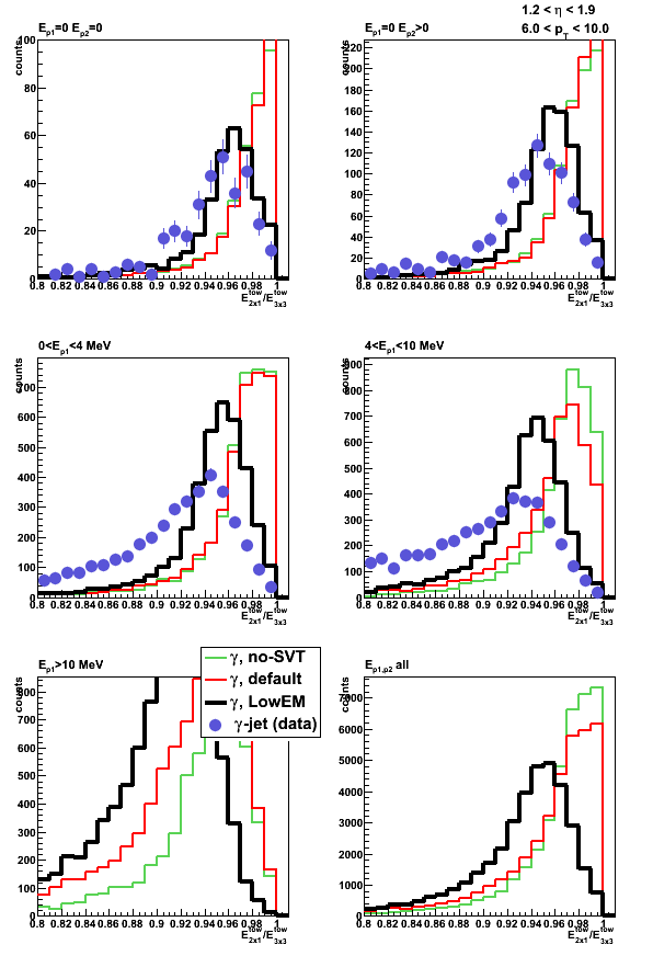
Figure 8b: Energy ratio in 2x1 to 3x3 cluster: 7 < pt < 8 and 1.2 < eta < 1.4
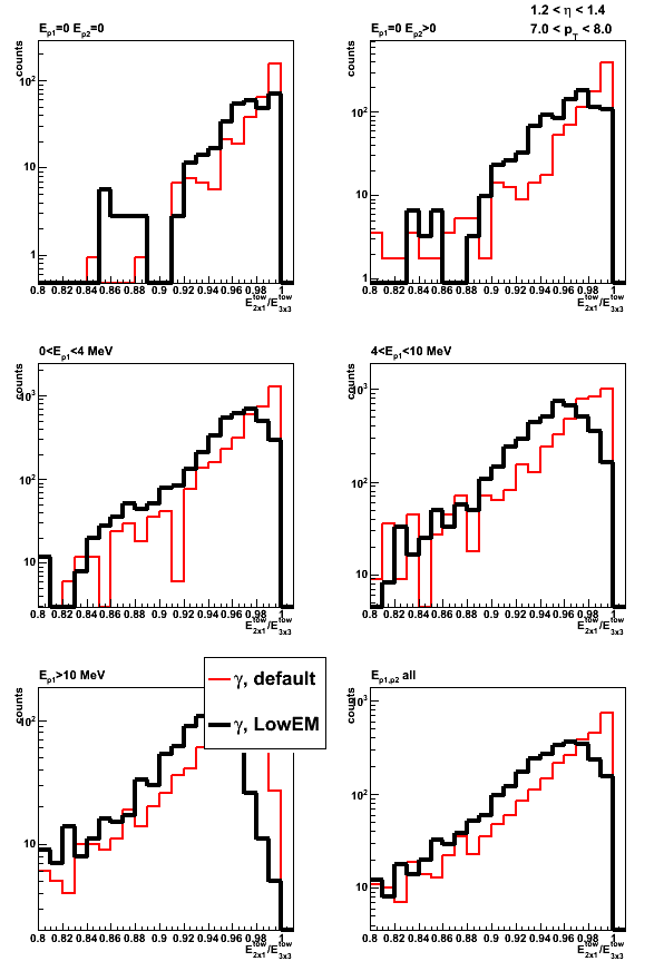
Figure 8c: Energy ratio in 2x1 to 3x3 cluster: 7 < pt < 8 and 1.6 < eta < 1.8
Figure 9: Average energy ratio in 2x1 to 3x3 cluster vs. thrown energy
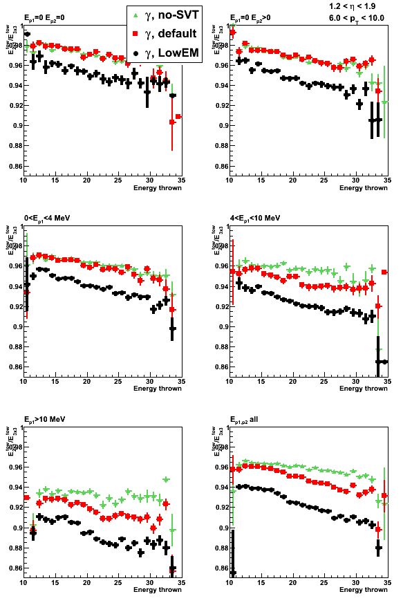
Figure 10: Average energy ratio in 2x1 to 3x3 cluster vs. thrown energy

LOW_EM cut definition
LOW_EM option for the STAR geometry (Low cuts on Electro-Magnetic processes)
is equivalent to the following set of GEANT cuts:
- CUTGAM=0.00001
- CUTELE=0.00001
- BCUTE =0.00001
- BCUTM =0.00001
- DCUTE =0.00001
- DCUTM =0.00001
All these values are for kinetic energy in GeV.
Cut meaning and GEANT default values:
- CUTGAM threshold for gamma transport (0.001);
- CUTELE threshold for electron and positron transport (0.001);
- BCUTE threshold for photons produced by electron bremsstrahlung (-1,);
- BCUTM threshold for photons produced by muon bremsstrahlung (-1);
- DCUTE threshold for electrons produced by electron delta-rays (-1);
- DCUTM threshold for electrons produced by muon or hadron delta-rays (-1);
Some details can be found at this link and in the GEANT manual
10 Oct
October 2009 posts
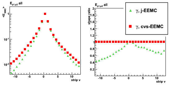
2009.10.02 Jason vs. CVS EEMC geometry: sampling fraction and shower shapes

Tests with Jason geometry file (ecalgeo.g23)
Monte-Carlo setup:
- One photon per event
- EEMC only geometry with LOW_EM option
- Throw particles flat in eta (1.08, 2.0), phi (0, 2pi), and pt (6-10 GeV)
- Using A2Emaker to get reconstructed Tower/SMD energy
(no EEMC SlowSimulator in chain) - Vertex z=0
- ~50K/per particle type
- Non-zero energy: 3 sigma above pedestal
Color coding:
- Photon with Jason geometry (single particle MC)
- Photon with CVS (cAir fix) geometry (single particle MC)
- Eta-meson [pp2006 data] (single photons from eta-meson decay)
Sampling fraction
Figure 1: Sampling fraction vs. thrown energy (upper plot)
and vs. azimuthal angle (lower left) and rapidity (lower right)

Shower shapes
Single particle kinematic cuts: pt=7-8GeV, eta=1.2-1.4
Eta-meson shower shapes (blue) taken from Fig. 1 from here of this post
All shapes are normalized to 1 at peak (central strip)
Figure 2: Shower shapes
Shower shapes sorted by pre-shower energy
Pre-shower bins:
- Ep1 = 0, Ep2 = 0 (no energy in both EEMC pre-shower layers)
- Ep1 = 0, Ep2 > 0
- 0 < Ep1 < 4 MeV
- 4 < Ep1 < 10 MeV
- Ep1 > 10 MeV
- All pre-shower bins combined
Ep1/Ep2 is the energy deposited in the 1st/2nd EEMC pre-shower layer.
For a single particle MC it is a sum over
all pre-shower tiles in the EEMC with energy of 3 sigma above pedestal.
For eta-meson from pp2006 data the sum is over 3x3 tower patch
Figure 3: Shower shapes (left) and their ratio (right)
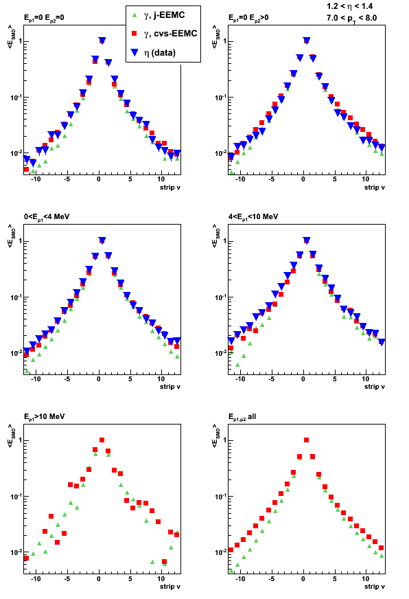
Figure 4: Shower shape ratios

2009.10.05 Fix to the Jason geometry file
Why volume numbers has changed in Jason geometry file?
The number of nested volumes (nv),
is the total number of parent volumes for the sensitive volume
(sensitive volume is indicated by the HITS in the tree structure below).
For the Jason and CVS files this nv number seems to be the same
(see block tree structures below).
Then why volume ids id in g2t tables has changed?
The answer I found (which seems trivial to me know)
is that in the original (CVS) file ECAL
block has been instantiated (positioned) twice.
The second appearance is the prototype (East) version of the Endcap
(Original ecalgeo.g from CVS)
        if (emcg_OnOff==1 | emcg_OnOff==3) then
             Position ECAL in CAVE z=+center
        endif
        if (emcg_OnOff==2 | emcg_OnOff==3) then
             Position ECAL in CAVE z=-center ThetaZ=180
        endif
In Jason version the second appearance has been removed
(what seems natural and it should not have any effect)
(ecalgeo.g Jason edits, g23):
        IF (emcg_OnOff>0) THEN
           Create ECAL

              .....

        IF (emcg_OnOff==2 ) THEN
           Prin1
             ('East Endcap has been removed from the geometry' )
        ENDIF               EndIF! emcg_OnOff
Unfortunately, this affects the way GEANT counts nested volumes
(effectively the total number was reduced by 1, from 8 to 7)
and this is the reason why the volume numbering scheme
in g2t tables has been affected.
I propose to put back these East Endcap line back,
since in this case it will not require any additional
changes to the EEMC decoder and g2t tables.
Block tree of the geometry file
blue - added volumes in Jason file
red - G10 volume removed in Jason file
HITS - sensitive volumes
---- Jason file ----
ECAL
EAGA
|EMSS
| -EFLP
| |ECVO
| | |EMOD
| | | |ESEC
| | | | |ERAD
| | | | | -ELED
| | | | |EMGT
| | | | | |EPER
| | | | | | |ETAR
| | | | | | | -EALP
| | | | | | | -ESCI -> HITS
| |ESHM
| | |ESPL
| | | |EXSG
| | | | -EXPS
| | | | -EHMS -> HITS
| | | | -EBLS
| | | | -EFLS
| | |ERSM
| -ESSP
| -ERCM
| -EPSB
|ECGH
| -ECHC
---- CVS file ----
ECAL
EAGA
|EMSS
| -EFLP
| |ECVO
| | |EMOD
| | | |ESEC
| | | | |ERAD
| | | | | -ELED
| | | | |EMGT
| | | | | |EPER
| | | | | | |ETAR
| | | | | | | -EALP
| | | | | | | -ESCI -> HITS
| |ESHM
| | |ESPL
| | | |EXSG
| | | | -EHMS -> HITS
| | | -EXGT
| | -ERSM
| -ESSP
| -ERCM
| -EPSB
|ECGH
| -ECHC
Block definitions
Jason geometry file
Create ECAL

Block ECAL is one EMC EndCap wheel
  Create and Position EAGA AlphaZ=halfi
EndBlock

Block EAGA IS HALF OF WHEEL AIR VOLUME FORTHE ENDCAP MODULE
  Create AND Position EMSS konly='MANY'
  Create AND Position ECGH alphaz=90 kOnly='ONLY'
EndBlock

Block EMSS is the steel support of the endcap module
  Create AND Position EFLP z=zslice-center+zwidth/2
  Create AND Position ECVO z=zslice-center+zwidth/2
  Create AND Position ESHM z=zslice-center+zwidth/2 kOnly='MANY'
  Create AND Position ECVO z=zslice-center+zwidth/2
  Create AND Position ESSP z=zslice-center+zwidth/2
  Create ERCM
  Create EPSB
EndBlock

Block ECVO is one of endcap volume with megatiles and radiators
  Create AND Position EMOD alphaz=d3 ncopy=i_sector
EndBlock

Block ESHM is the shower maxsection
  Create and Position ESPL z=currentk Only='MANY'
  Create ERSM
EndBlock

Block ECGH is air gap between endcap half wheels
  Create ECHC
EndBlock

Block ECHC is steel endcap half cover
EndBlock

Block ESSP is stainless steelback plate
EndBlock

Block EPSB IS A PROJECTILE STAINLESS STEEL BAR
EndBlock

Block ERCM is stainless steel tie rod in calorimeter sections
EndBlock

Block ERSM is stainless steel tie rod in shower max
EndBlock

Block EMOD (fsect,lsect) IS ONE MODULEOF THE EM ENDCAP
  Create AND Position ESEC z=section-curr+secwid/2
EndBlock

Block ESEC is a single em section
  Create AND Position ERAD z=length+(cell)/2+esec_deltaz
  Create AND Position EMGT z=length+(gap+cell)/2+esec_deltaz
  Create AND Position ERAD z=length+cell/2+esec_deltaz
EndBlock

Block EMGT is a 30 degree megatile
  Create AND Position EPER alphaz=myPhi
EndBlock

Block EPER is a 5 degree slice of a 30 degree megatile (subsector)
  Create and Position ETAR x=(rbot+rtop)/2ort=yzx
EndBlock

Block ETAR is a single calorimeter cell, containing scintillator, fiber router, etc...
  Create AND Position EALP y=(-megatile+emcs_alincell)/2
  Create AND Position ESCI y=(-megatile+g10)/2+emcs_alincell _
EndBlock

Block ESCI is the active scintillator (polystyrene) layer
EndBlock

Block ERAD is the lead radiator with stainless steel cladding
  Create AND Position ELED
EndBlock

Block ELED is a lead absorber plate
EndBlock

Block EFLP is the aluminum (aluminium) front plate of the endcap
EndBlock

Block EALP is the thin aluminium plate in calorimeter cell
EndBlock

Block ESPL is the logical volume containing an SMD plane
  Create and Position EXSG alphaz=d3 ncopy=isec kOnly='MANY'
  Create and Position EXSG alphaz=d3 ort=x-y-z ncopy=isec kOnly='MANY'
  Create and Position EXSG alphaz=d3 ncopy=isec kOnly='MANY'
  Create and Position EXSG alphaz=d3 ort=x-y-z ncopy=isec kOnly='MANY'
  Create and Position EXSG alphaz=d3 ncopy=isec kOnly='MANY'
EndBlock

Block EXSG Is another logical volume... this one acutally creates the planes
  Create and Position EXPS kONLY='MANY'
  Create and Position EHMS x=xc y=yc alphaz=-45 kOnly='ONLY'
  Create and Position EBLS x=xc y=yc z=(+esmd_apex/2+esmd_back_layer/2) alphaz=-45 kOnly='ONLY'
  Create and Position EHMS x=xc y=yc alphaz=-45 ort=x-y-z kOnly='ONLY'
  Create and Position EFLS x=xc y=yc z=(-esmd_apex/2-esmd_front_layer/2) alphaz=-45 ort=x-y-z kOnly='ONLY'
EndBlock

Block EHMS defines the triangular SMD strips
Endblock! EHMS

Block EFLS is the layer of material on the front of the SMD planes
EndBlock! EFLS

Block EBLS is the layer of material on the back of the SMD planes
EndBlock! EFLS

Block EXPS is the plastic spacer in the shower maximum section
EndBlock
CVS geometry file
Create ECAL

Block ECAL is one EMC EndCap wheel
  Create and Position EAGA AlphaZ=halfi
EndBlock

Block EAGA is half of wheel air volume forthe EndCap module
  Create and Position EMSS konly='MANY'
  Create and Position ECGH AlphaZ=90 konly='ONLY'
EndBlock

Block EMSS is steel support of the EndCap module
  Create and Position EFLP z=zslice-center+slcwid/2
  Create and Position ECVO z=zslice-center+slcwid/2
  Create and Position ESHM z=zslice-center+slcwid/2
  Create and Position ECVO z=zslice-center+slcwid/2
  Create and Position ESSP z=zslice-center+slcwid/2
  Create ERCM
  Create EPSB
EndBlock

Block ECVO is one of EndCap Volume with megatiles and radiators
  Create and Position EMOD AlphaZ=d3 Ncopy=J_section
EndBlock

Block ESHM is the SHower Maxsection
  Create and Position ESPL z=current
  Create ERSM
Endblock

Block ECGH is air Gap between endcap Half wheels
  Create ECHC
EndBlock

Block ECHC is steel EndCap Half Cover
EndBlock

Block ESSP is Stainless Steelback Plate
endblock

Block EPSB is Projectile Stainless steel Bar
endblock

Block ERCM is stainless steel tie Rod in CaloriMeter sections
endblock

Block ERSM is stainless steel tie Rod in Shower Max
endblock

Block EMOD is one moduleof the EM EndCap
  Create and Position ESEC z=section-curr+secwid/2
endblock

Block ESEC is a single EM section
  Create and Position ERAD z=len + (cell)/2
  Create and Position EMGT z=len +(gap+cell)/2
  Create and Position ERAD z=len + cell/2
Endblock

Block EMGT is a megatile EM section
  Create and Position EPER AlphaZ=(emcs_Nslices/2-isec+0.5)*dphi
Endblock

Block EPER is a EM subsection period (super layer)
  Create and Position ETAR x=(RBot+RTop)/2ORT=YZX
EndBlock

Block ETAR is one CELL of scintillator, fiber and plastic
  Create and Position EALP y=(-mgt+emcs_AlinCell)/2
  Create and Position ESCI y=(-mgt+G10)/2+emcs_AlinCell _
EndBlock

Block ESCI is the active scintillator (polystyren) layer
endblock

Block ERAD is radiator
  Create and PositionELED
endblock

Block ELED is lead absorber Plate
endblock

Block EFLP is First Aluminium plate
endblock

Block EALP is ALuminiumPlate in calorimeter cell
endblock

Block ESPL is one of the Shower maxPLanes
  Create and position EXSG AlphaZ=d3Ncopy=isec
  Create and position EXSG AlphaZ=d3Ncopy=isec
  Create and position EXGT z=msecwd AlphaZ=d3
  Create and position EXSG AlphaZ=d3 ORT=X-Y-Z Ncopy=isec
  Create and position EXGT z=-msecwd AlphaZ=d3
  Create and position EXSG AlphaZ=d3Ncopy=isec
  Create and position EXGT z=msecwd AlphaZ=d3
  Create and position EXSG AlphaZ=d3 ORT=X-Y-Z Ncopy=isec
  Create and position EXGT z=-msecwd AlphaZ=d3
Endblock

Block EXSG is the Shower maxGap for scintillator strips
  Create EHMS
endblock

Block EHMS is sHower Max Strip
Endblock

Block EXGT is the G10 layer in the Shower Max
EndBlock
Original (ecalgeo.g) file from CVS
Original (ecalgeo.g) file from CVS
****************************************************************************** Module ECALGEO is the EM EndCap Calorimeter GEOmetry Created 26 jan 1996 Author Rashid Mehdiyev * * Version 1.1, W.J. Llope * - changed sensitive medium names... * * Version 2.0, R.R. Mehdiyev 16.04.97 * - Support walls included * - intercell and intermodule gaps width updated * - G10 layers inserted * Version 2.1, R.R. Mehdiyev 23.04.97 * - Shower Max Detector geometry added * - Variable eta grid step size introduced * Version 2.2, R.R. Mehdiyev 03.12.97 * - Eta grid corrected * - Several changes in volume's dimensions * - Material changes in SMD * * Version 3.0, O. Rogachevsky 28.11.99 * - New proposal for calorimeter SN 0401 * * Version 4.1, O.Akio 3 Jan 01 * - Include forward pion detectors * Version 5.0, O. Rogachevsky 20.11.01 * - FPD is eliminated in this version * - More closed to proposal description * of calorimeter and SMD structure * ****************************************************************************** +CDE,AGECOM,GCONST,GCUNIT. * Content EAGA,EALP,ECAL,ECHC,ECVO,ECGH,EFLP,EHMS, ELED,EMGT,EMOD,EPER,EPSB,ERAD,ERCM,ERSM, ESHM,ESEC,ESCI,ESGH,ESPL,ESSP,EMSS, ETAR,EXGT,EXSG * Structure EMCG { Version, int Onoff, int fillMode} Structure EMCS { Type,ZOrig,ZEnd,EtaMin,EtaMax, PhiMin,PhiMax,Offset, Nsupsec,Nsector,Nsection,Nslices, Front,AlinCell,Frplast,Bkplast,PbPlate,LamPlate, BckPlate,Hub,Rmshift,SMShift,GapPlt,GapCel, GapSMD,SMDcentr,TieRod(2),Bckfrnt,GapHalf,Cover} * Structure EETR { Type,Etagr,Phigr,Neta,EtaBin(13)} * Structure ESEC { Isect, FPlmat, Cell, Scint, Nlayer } * Structure EMXG {Version,Sapex,Sbase,Rin,Rout,F4} * Structure EXSE {Jsect,Zshift,Sectype(6)} * Integer I_section,J_section,Ie,is,isec,i_str,Nstr,Type,ii,jj, cut,fsect,lsect,ihalf,filled * Real center,Plate,Cell,G10,diff,halfi, tan_low,tan_upp,Tanf,RBot,Rtop,Deta,etax,sq2,sq3, dup,dd,d2,d3,rshift,dphi,radiator,orgkeep,endkeep * Real maxcnt,msecwd,mxgten,curr,Secwid,Section, curcl,EtaTop,EtaBot,slcwid,zslice,Gap,mgt, xleft,xright,yleft,yright,current, rth,len,p,xc,yc,xx,yy,rbotrad, Rdel,dxy,ddn,ddup Integer N Parameter (N=12) * Tanf(etax) = tan(2*atan(exp(-etax))) * * ---------------------------------------------------------------------------- * * FillMode =1 only 2-5 sectors (in the first half) filled with scintillators * FillMode =2 all sectors filled (still only one half of one side) * FillMode =3 both halves (ie all 12 sectors are filled) Fill EMCG ! EM EndCAp Calorimeter basic data Version = 5.0 ! Geometry version OnOff = 3 ! Configurations 0-no, 1-west 2-east 3-both FillMode = 3 ! sectors fill mode Fill EMCS ! EM Endcap Calorimeter geometry Type = 1 ! =1 endcap, =2 fpd edcap prototype ZOrig = 268.763 ! calorimeter origin in z ZEnd = 310.007 ! Calorimeter end in z EtaMin = 1.086 ! upper feducial eta cut EtaMax = 2.0, ! lower feducial eta cut PhiMin = -90 ! Min phi PhiMax = 90 ! Max phi Offset = 0.0 ! offset in x Nsupsec = 6 ! Number of azimuthal supersectors Nsector = 30 ! Number of azimutal sectors (Phi granularity) Nslices = 5 ! number of phi slices in supersector Nsection = 4 ! Number of readout sections Front = 0.953 ! thickness of the front AL plates AlinCell = 0.02 ! Aluminim plate in cell Frplast = 0.015 ! Front plastic in megatile Bkplast = 0.155 ! Fiber routing guides and back plastic Pbplate = 0.457 ! Lead radiator thickness LamPlate = 0.05 ! Laminated SS plate thickness BckPlate = 3.175 ! Back SS plate thickness Hub = 3.81 ! thickness of EndCap hub Rmshift = 2.121 ! radial shift of module smshift = 0.12 ! radial shift of steel support walls GapPlt = 0.3/2 ! HALF of the inter-plate gap in phi GapCel = 0.03/2 ! HALF of the radial inter-cell gap GapSMD = 3.400 ! space for SMD detector SMDcentr = 279.542 ! SMD position TieRod = {160.,195} ! Radial position of tie rods Bckfrnt = 306.832 ! Backplate front Z GapHalf = 0.4 ! 1/2 Gap between halves of endcap wheel Cover = 0.075 ! Cover of wheel half * Rmshift = 2.121 ! radial shift of module * -------------------------------------------------------------------------- Fill EETR ! Eta and Phi grid values Type = 1 ! =1 endcap, =2 fpd EtaGr = 1.0536 ! eta_top/eta_bot tower granularity PhiGr = 0.0981747 ! Phi granularity (radians) NEta = 12 ! Eta granularity EtaBin = {2.0,1.9008,1.8065,1.7168,1.6317,1.5507,1.4738, 1.4007,1.3312,1.2651,1.2023,1.1427,1.086}! Eta rapidities *--------------------------------------------------------------------------- Fill ESEC ! First EM section ISect = 1 ! Section number Nlayer = 1 ! Number of Sci layers along z Cell = 1.505 ! Cell full width in z Scint = 0.5 ! Sci layer thickness * Fill ESEC ! First EM section ISect = 2 ! Section number Nlayer = 1 ! Number of Sci layers along z Cell = 1.505 ! Cell full width in z Scint = 0.5 ! Sci layer thickness * Fill ESEC ! Second EM section ISect = 3 ! Section number Nlayer = 4 ! Number of Sci layers along z Cell = 1.405 ! Cell full width in z Scint = 0.4 ! Sci layer thickness * Fill ESEC ! Third EM section ISect = 4 ! Section Nlayer = 18 ! Number of layers along z Cell = 1.405 ! Cell full width in z Scint = 0.4 ! Sci layer thickness * Fill ESEC ! 4th EM section ISect = 5 ! Section Nlayer = 1 ! Number of layers along z Cell = 1.505 ! Cell full width in z Scint = 0.5 ! Sci layer thickness *---------------------------------------------------------------------------- Fill EMXG ! EM Endcap SMD basic data Version = 1 ! Geometry version Sapex = 0.7 ! Scintillator strip apex Sbase = 1.0 ! Scintillator strip base Rin = 77.41 ! inner radius of SMD plane Rout = 213.922 ! outer radius of SMD plane F4 = .15 ! F4 thickness *---------------------------------------------------------------------------- Fill EXSE ! First SMD section JSect = 1 ! Section number Zshift = -1.215 ! Section width sectype = {4,1,0,2,1,0} ! 1-V,2-U,3-cutV,4-cutU * Fill EXSE ! Second SMD section JSect = 2 ! Section number Zshift = 0. ! Section width sectype = {0,2,1,0,2,3} ! 1-V,2-U,3-cutV,4-cutU * Fill EXSE ! Third SMD section JSect = 3 ! Section number Zshift = 1.215 ! Section width sectype = {1,0,2,1,0,2} ! 1-V,2-U,3-cutV,4-cutU *---------------------------------------------------------------------------- * Use EMCG * sq3 = sqrt(3.) sq2 = sqrt(2.) prin1 emcg_version ('ECALGEO version ', F4.2) * Endcap USE EMCS type=1 USE EETR type=1 orgkeep = emcs_ZOrig endkeep = emcs_ZEnd if(emcg_OnOff>0) then diff = 0.0 center = (emcs_ZOrig+emcs_ZEnd)/2 Tan_Upp = tanf(emcs_EtaMin) Tan_Low = tanf(emcs_EtaMax) rth = sqrt(1. + Tan_Low*Tan_Low) rshift = emcs_Hub * rth dup=emcs_Rmshift*Tan_Upp dd=emcs_Rmshift*rth d2=rshift + dd radiator = emcs_Pbplate + 2*emcs_LamPlate * d3=emcs_Rmshift-2*emcs_smshift dphi = (emcs_PhiMax-emcs_PhiMin)/emcs_Nsector Create ECAL if (emcg_OnOff==1 | emcg_OnOff==3) then Position ECAL in CAVE z=+center endif if (emcg_OnOff==2 | emcg_OnOff==3) then Position ECAL in CAVE z=-center ThetaZ=180 endif if(section > emcs_Zend) then prin0 section,emcs_Zend (' ECALGEO error: sum of sections exceeds maximum ',2F12.4) endif prin1 section (' EndCap calorimeter total depth ',F12.4) endif prin1 ('ECALGEO finished') * * ---------------------------------------------------------------------------- Block ECAL is one EMC EndCap wheel Material Air Medium standard Attribute ECAL seen=1 colo=7 ! lightblue shape CONE dz=(emcs_Zend-emcs_ZOrig)/2, Rmn1=orgkeep*Tan_Low-d2 Rmn2=endkeep*Tan_Low-d2, Rmx1=orgkeep*Tan_Upp+dup Rmx2=endkeep*Tan_Upp+dup do ihalf=1,2 filled=1 halfi = -105 + (ihalf-1)*180 if (ihalf=2 & emcg_FillMode<3) filled = 0 Create and Position EAGA AlphaZ=halfi enddo * EndBlock * ---------------------------------------------------------------------------- Block EAGA is half of wheel air volume for the EndCap module Attribute EAGA seen=1 colo=1 serial=filled ! black Material Air shape CONS dz=(emcs_Zend-emcs_ZOrig)/2, Rmn1=orgkeep*Tan_Low-d2 Rmn2=endkeep*Tan_Low-d2, Rmx1=orgkeep*Tan_Upp+dup Rmx2=endkeep*Tan_Upp+dup, phi1=emcs_PhiMin phi2=emcs_PhiMax if (filled=1) then Create and Position EMSS konly='MANY' curr = orgkeep ; curcl = endkeep Create and position ECGH AlphaZ=90 konly='ONLY' endif EndBlock * ---------------------------------------------------------------------------- Block EMSS is steel support of the EndCap module Attribute EMSS seen=1 colo=1 ! black Material Iron shape CONS dz=(emcs_Zend-emcs_ZOrig)/2, Rmn1=orgkeep*Tan_Low-d2 Rmn2=endkeep*Tan_Low-d2, Rmx1=orgkeep*Tan_Upp+dup Rmx2=endkeep*Tan_Upp+dup, phi1=emcs_PhiMin phi2=emcs_PhiMax zslice = emcs_ZOrig prin1 zslice (' Front Al plane starts at: ',F12.4) slcwid = emcs_Front Create and Position EFLP z=zslice-center+slcwid/2 zslice = zslice + slcwid prin1 zslice (' First calorimeter starts at: ',F12.4) fsect = 1; lsect = 3 slcwid = emcs_SMDcentr - emcs_GapSMD/2 - zslice * Create and Position ECVO z=zslice-center+slcwid/2 slcwid = emcs_GapSMD zslice = emcs_SMDcentr - emcs_GapSMD/2 prin1 section,zslice (' 1st calorimeter ends, SMD starts at: ',2F10.5) Create and Position ESHM z=zslice-center+slcwid/2 zslice = zslice + slcwid prin1 zslice (' SMD ends at: ',F10.5) * slcwid = 0 fsect = 4; lsect = 5 do I_section =fsect,lsect USE ESEC Isect=I_section Slcwid = slcwid + esec_cell*esec_Nlayer enddo slcwid = emcs_bckfrnt - zslice * Create and Position ECVO z = zslice-center+slcwid/2 zslice = emcs_bckfrnt prin1 section,zslice (' 2nd calorimeter ends, Back plate starts at: ',2F10.5) slcwid = emcs_BckPlate * Create and Position ESSP z=zslice-center+slcwid/2 zslice = zslice + slcwid prin1 zslice (' BackPlate ends at: ',F10.5) slcwid = emcs_Zend-emcs_ZOrig Create ERCM do i_str = 1,2 do is = 1,5 xx = emcs_phimin + is*30 yy = xx*degrad xc = cos(yy)*emcs_TieRod(i_str) yc = sin(yy)*emcs_TieRod(i_str) Position ERCM z=0 x=xc y=yc enddo enddo rth = orgkeep*Tan_Upp+dup + 2.5/2 xc = (endkeep - orgkeep)*Tan_Upp len = .5*(endkeep + orgkeep)*Tan_Upp + dup + 2.5/2 yc = emcs_Zend-emcs_ZOrig p = atan(xc/yc)/degrad Create EPSB do is = 1,6 xx = -75 + (is-1)*30 yy = xx*degrad xc = cos(yy)*len yc = sin(yy)*len Position EPSB x=xc y=yc AlphaZ=xx enddo EndBlock * ---------------------------------------------------------------------------- Block ECVO is one of EndCap Volume with megatiles and radiators Material Air Attribute ECVO seen=1 colo=3 ! green shape CONS dz=slcwid/2, Rmn1=zslice*Tan_Low-dd Rmn2=(zslice+slcwid)*Tan_Low-dd, Rmx1=zslice*Tan_Upp+dup Rmx2=(zslice+slcwid)*Tan_Upp+dup do J_section = 1,6 if (1 < J_section < 6 | emcg_FillMode > 1)then filled = 1 else filled = 0 endif d3 = 75 - (J_section-1)*30 Create and Position EMOD AlphaZ=d3 Ncopy=J_section enddo * EndBlock * ---------------------------------------------------------------------------- Block ESHM is the SHower Max section * Material Air Attribute ESHM seen=1 colo=4 ! blue Shape CONS dz=SlcWid/2, rmn1=zslice*Tan_Low-dd, rmn2=(zslice+slcwid)*Tan_Low-dd, rmx1=(zslice)*Tan_Upp+dup, rmx2=(zslice+slcwid)*Tan_Upp+dup, phi1=emcs_PhiMin phi2=emcs_PhiMax USE EMXG Version=1 maxcnt = emcs_SMDcentr prin1 zslice,section,center (' Z start for SMD,section: ',3F12.4) * do J_section = 1,3 USE EXSE Jsect=J_section * current = exse_Zshift secwid = emxg_Sapex + 2.*emxg_F4 section = maxcnt + exse_zshift prin1 j_section,current,section,secwid (' layer, Z, width : ',i3,3F12.4) rbot=section*Tan_Low rtop=section*Tan_Upp prin1 j_section,rbot,rtop (' layer, rbot,rtop : ',i3,2F12.4) Create and position ESPL z=current * end do Create ERSM do i_str = 1,2 do is = 1,5 xx = emcs_phimin + (is)*30 yy = xx*degrad xc = cos(yy)*emcs_TieRod(i_str) yc = sin(yy)*emcs_TieRod(i_str) Position ERSM z=0 x=xc y=yc enddo enddo Endblock * ---------------------------------------------------------------------------- Block ECGH is air Gap between endcap Half wheels Material Air Medium standard Attribute ECGH seen=0 colo=7 ! lightblue shape TRD1 dz=(emcs_Zend-emcs_ZOrig)/2, dy =(emcs_gaphalf+emcs_cover)/2, dx1=orgkeep*Tan_Upp+dup, dx2=endkeep*Tan_Upp+dup rth = emcs_GapHalf + emcs_cover xx=curr*Tan_Low-d2 xleft = sqrt(xx*xx - rth*rth) yy=curr*Tan_Upp+dup xright = sqrt(yy*yy - rth*rth) secwid = yy - xx xx=curcl*Tan_Low-d2 yleft = sqrt(xx*xx - rth*rth) yy=curcl*Tan_Upp+dup yright = sqrt(yy*yy - rth*rth) slcwid = yy - xx xx=(xleft+xright)/2 yy=(yleft + yright)/2 xc = yy - xx len = (xx+yy)/2 yc = curcl - curr p = atan(xc/yc)/degrad rth = -(emcs_GapHalf + emcs_cover)/2 Create ECHC Position ECHC x=len y=rth Position ECHC x=-len y=rth AlphaZ=180 EndBlock * ---------------------------------------------------------------------------- Block ECHC is steel EndCap Half Cover Attribute ECHC seen=1 colo=1 ! black Material Iron shape TRAP dz=(curcl-curr)/2, thet=p, bl1=secwid/2, tl1=secwid/2, bl2=slcwid/2, tl2=slcwid/2, h1=emcs_cover/2 h2=emcs_cover/2, phi=0 alp1=0 alp2=0 EndBlock * ---------------------------------------------------------------------------- Block ESSP is Stainless Steel back Plate * Material Iron Attribute ESSP seen=1 colo=6 fill=1 shape CONS dz=emcs_BckPlate/2, Rmn1=zslice*Tan_Low-dd Rmn2=(zslice+slcwid)*Tan_Low-dd, Rmx1=zslice*Tan_Upp+dup Rmx2=(zslice+slcwid)*Tan_Upp+dup, phi1=emcs_PhiMin phi2=emcs_PhiMax endblock * ---------------------------------------------------------------------------- Block EPSB is Projectile Stainless steel Bar * Material Iron Attribute EPSB seen=1 colo=6 fill=1 shape TRAP dz=(emcs_Zend-emcs_ZOrig)/2, thet=p, bl1=2.5/2, tl1=2.5/2, bl2=2.5/2, tl2=2.5/2, h1=2.0/2 h2=2.0/2, phi=0 alp1=0 alp2=0 endblock * ---------------------------------------------------------------------------- Block ERCM is stainless steel tie Rod in CaloriMeter sections * Material Iron Attribute ERSM seen=1 colo=6 fill=1 shape TUBE dz=slcwid/2, rmin=0, rmax=1.0425 ! nobody knows exactly endblock * ---------------------------------------------------------------------------- Block ERSM is stainless steel tie Rod in Shower Max * Material Iron Attribute ERSM seen=1 colo=6 fill=1 shape TUBE dz=slcwid/2, rmin=0, rmax=1.0425 endblock * ---------------------------------------------------------------------------- Block EMOD is one module of the EM EndCap Attribute EMOD seen=1 colo=3 serial=filled ! green Material Air Shape CONS dz=slcwid/2, phi1=emcs_PhiMin/emcs_Nsupsec, phi2=emcs_PhiMax/emcs_Nsupsec, Rmn1=zslice*Tan_Low-dd Rmn2=(zslice+slcwid)*Tan_Low-dd, Rmx1=zslice*Tan_Upp+dup Rmx2=(zslice+slcwid)*Tan_Upp+dup * * Running parameter 'section' contains the position of the current section * It should not be modified in daughters, use 'current' variable instead. * SecWid is used in all 'CONS' daughters to define dimensions. * * section = zslice curr = zslice + slcwid/2 Do I_section =fsect,lsect USE ESEC Isect=I_section * Secwid = esec_cell*esec_Nlayer if (I_section = 3 | I_section = 5) then ! no last radiator Secwid = Secwid - radiator else if (I_section = 4) then ! add one more radiator Secwid = Secwid - esec_cell + radiator endif Create and position ESEC z=section-curr+secwid/2 section = section + secwid * enddo endblock * ---------------------------------------------------------------------------- Block ESEC is a single EM section Attribute ESEC seen=1 colo=1 serial=filled Material Air Medium standard * Shape CONS dz=secwid/2, rmn1=(section-diff)*Tan_Low-dd, rmn2=(section+secwid-diff)*Tan_Low-dd, rmx1=(section-diff)*Tan_Upp+dup, rmx2=(section+secwid-diff)*Tan_Upp+dup * len = -secwid/2 current = section mgt = esec_scint + emcs_AlinCell _ + emcs_FrPlast + emcs_BkPlast gap = esec_cell - radiator - mgt prin2 I_section,section (' ESEC:I_section,section',i3,F12.4) Do is = 1,esec_Nlayer * define actual cell thickness: Cell = esec_cell plate = radiator * if (is=nint(esec_Nlayer) & (I_section = 3 | I_section = 5)) then Cell = mgt + gap Plate=0 else if (I_section = 4 & is = 1) then ! radiator only Cell = radiator endif * prin2 I_section,is,len,cell,current (' ESEC:I_section,is,len,cell,current ',2i3,3F12.4) if (I_section = 4 & is = 1) then ! radiator only cell = radiator + .14 Create and Position ERAD z=len + (cell)/2 len = len + cell current = current + cell else cell = mgt if(filled = 1) then Create and Position EMGT z=len +(gap+cell)/2 xx = current + (gap+cell)/2 prin2 I_section,is,xx (' MEGA I_section,is ',2i3,F10.4) endif len = len + cell + gap current = current + cell + gap if (Plate>0) then cell = radiator Create and Position ERAD z=len + cell/2 len = len + cell current = current + cell end if end if end do Endblock * ---------------------------------------------------------------------------- Block EMGT is a megatile EM section Attribute EMGT seen=1 colo=1 Material Air Medium standard * Shape CONS dz=mgt/2, rmn1=(current-diff)*Tan_Low-dd, rmn2=(current+mgt-diff)*Tan_Low-dd, rmx1=(current-diff)*Tan_Upp+dup, rmx2=(current+mgt-diff)*Tan_Upp+dup if (I_section=1 | I_section=2 | I_section=5) then Call GSTPAR (ag_imed,'CUTGAM',0.00001) Call GSTPAR (ag_imed,'CUTELE',0.00001) else Call GSTPAR (ag_imed,'CUTGAM',0.00008) Call GSTPAR (ag_imed,'CUTELE',0.001) Call GSTPAR (ag_imed,'BCUTE',0.0001) end if * Do isec=1,nint(emcs_Nslices) Create and Position EPER AlphaZ=(emcs_Nslices/2-isec+0.5)*dphi End Do Endblock *--------------------------------------------------------------------------- Block EPER is a EM subsection period (super layer) * Material POLYSTYREN Attribute EPER seen=1 colo=1 Shape CONS dz=mgt/2, phi1=emcs_PhiMin/emcs_Nsector, phi2=+emcs_PhiMax/emcs_Nsector, rmn1=(current-diff)*Tan_Low-dd, rmn2=(current+mgt-diff)*Tan_Low-dd, rmx1=(current-diff)*Tan_Upp+dup, rmx2=(current+mgt-diff)*Tan_Upp+dup * curcl = current+mgt/2 Do ie = 1,nint(eetr_NEta) EtaBot = eetr_EtaBin(ie) EtaTop = eetr_EtaBin(ie+1) RBot=(curcl-diff)*Tanf(EtaBot) * if(Plate > 0) then ! Ordinary Sci layer RTop=min((curcl-diff)*Tanf(EtaTop), _ ((current-diff)*Tan_Upp+dup)) else ! last Sci layer in section RTop=min((curcl-diff)*Tanf(EtaTop), _ ((current-diff)*Tan_Upp+dup)) endif check RBot<RTop * xx=tan(pi*emcs_PhiMax/180.0/emcs_Nsector) yy=cos(pi*emcs_PhiMax/180.0/emcs_Nsector) Create and Position ETAR x=(RBot+RTop)/2 ORT=YZX prin2 ie,EtaTop,EtaBot,rbot,rtop (' EPER : ie,EtaTop,EtaBot,rbot,rtop ',i3,4F12.4) enddo * EndBlock * - - - - - - - - - - - - - - - - - - - - - - - - - - - - - - - - - - - - - - Block ETAR is one CELL of scintillator, fiber and plastic * Attribute ETAR seen=1 colo=4 ! blue * local z goes along the radius, y is the thickness Shape TRD1 dy=mgt/2 dz=(RTop-RBot)/2, dx1=RBot*xx-emcs_GapCel/yy, dx2=RTop*xx-emcs_GapCel/yy * Create and Position EALP y=(-mgt+emcs_AlinCell)/2 G10 = esec_scint Create and Position ESCI y=(-mgt+G10)/2+emcs_AlinCell _ +emcs_FrPlast EndBlock * - - - - - - - - - - - - - - - - - - - - - - - - - - - - - - - - - - - - - - Block ESCI is the active scintillator (polystyren) layer * Material POLYSTYREN Material Cpolystyren Isvol=1 Attribute ESCI seen=1 colo=7 fill=0 ! lightblue * local z goes along the radius, y is the thickness Shape TRD1 dy=esec_scint/2, dz=(RTop-RBot)/2-emcs_GapCel Call GSTPAR (ag_imed,'CUTGAM',0.00008) Call GSTPAR (ag_imed,'CUTELE',0.001) Call GSTPAR (ag_imed,'BCUTE',0.0001) Call GSTPAR (ag_imed,'CUTNEU',0.001) Call GSTPAR (ag_imed,'CUTHAD',0.001) Call GSTPAR (ag_imed,'CUTMUO',0.001) * define Birks law parameters Call GSTPAR (ag_imed,'BIRK1',1.) Call GSTPAR (ag_imed,'BIRK2',0.013) Call GSTPAR (ag_imed,'BIRK3',9.6E-6) * HITS ESCI Birk:0:(0,10) * xx:16:H(-250,250) yy:16:(-250,250) zz:16:(-350,350), * px:16:(-100,100) py:16:(-100,100) pz:16:(-100,100), * Slen:16:(0,1.e4) Tof:16:(0,1.e-6) Step:16:(0,100), * none:16: endblock * ---------------------------------------------------------------------------- Block ERAD is radiator * Material Iron Attribute ERAD seen=1 colo=6 fill=1 ! violet Shape CONS dz=radiator/2, rmn1=(current)*Tan_Low-dd, rmn2=(current+cell)*Tan_Low-dd, rmx1=(current)*Tan_Upp+dup, rmx2=(current+radiator)*Tan_Upp+dup Create and Position ELED endblock * - - - - - - - - - - - - - - - - - - - - - - - - - - - - - - - - - - - - - Block ELED is lead absorber Plate * Material Lead Attribute ELED seen=1 colo=4 fill=1 Shape TUBS dz=emcs_Pbplate/2, rmin=(current)*Tan_Low, rmax=(current+emcs_Pbplate)*Tan_Upp, Call GSTPAR (ag_imed,'CUTGAM',0.00008) Call GSTPAR (ag_imed,'CUTELE',0.001) Call GSTPAR (ag_imed,'BCUTE',0.0001) Call GSTPAR (ag_imed,'CUTNEU',0.001) Call GSTPAR (ag_imed,'CUTHAD',0.001) Call GSTPAR (ag_imed,'CUTMUO',0.001) endblock * ---------------------------------------------------------------------------- Block EFLP is First Aluminium plate * Material Aluminium Attribute EFLP seen=1 colo=3 fill=1 ! green shape CONS dz=emcs_Front/2, Rmn1=68.813 Rmn2=68.813, Rmx1=(zslice-diff)*Tan_Upp+dup, Rmx2=(zslice + slcwid-diff)*Tan_Upp+dup, phi1=emcs_PhiMin phi2=emcs_PhiMax endblock * ---------------------------------------------------------------------------- Block EALP is ALuminium Plate in calorimeter cell * Material Aluminium Material StrAluminium isvol=0 Attribute EALP seen=1 colo=1 Shape TRD1 dy=emcs_AlinCell/2 dz=(RTop-RBot)/2 Call GSTPAR (ag_imed,'CUTGAM',0.00001) Call GSTPAR (ag_imed,'CUTELE',0.00001) Call GSTPAR (ag_imed,'LOSS',1.) Call GSTPAR (ag_imed,'STRA',1.) endblock * ---------------------------------------------------------------------------- Block ESPL is one of the Shower max PLanes * Material Air Attribute ESPL seen=1 colo=3 ! blue Shape TUBS dz=SecWid/2, rmin=section*Tan_Low-1.526, rmax=(section-secwid/2)*Tan_Upp+dup, phi1=emcs_PhiMin phi2=emcs_PhiMax USE EMXG Version=1 msecwd = (emxg_Sapex+emxg_F4)/2 do isec=1,6 cut=1 d3 = 75 - (isec-1)*30 if (exse_sectype(isec) = 0 | (emcg_FillMode=1 & (isec=6 | isec=1))) then cut = 0 Create and position EXSG AlphaZ=d3 Ncopy=isec else if(exse_sectype(isec) = 1) then ! V Create and position EXSG AlphaZ=d3 Ncopy=isec Create and position EXGT z=msecwd AlphaZ=d3 else if(exse_sectype(isec) = 2) then ! U Create and position EXSG AlphaZ=d3 ORT=X-Y-Z Ncopy=isec Create and position EXGT z=-msecwd AlphaZ=d3 else if(exse_sectype(isec) = 3) then ! cut V cut=2 Create and position EXSG AlphaZ=d3 Ncopy=isec Create and position EXGT z=msecwd AlphaZ=d3 else if(exse_sectype(isec) = 4) then ! cut U cut=2 Create and position EXSG AlphaZ=d3 ORT=X-Y-Z Ncopy=isec Create and position EXGT z=-msecwd AlphaZ=d3 endif enddo Endblock * ---------------------------------------------------------------------------- Block EXSG is the Shower max Gap for scintillator strips * Attribute EXSG seen=1 colo=7 serial=cut ! black Material Air Shape TUBS dz=SecWid/2, rmin=section*Tan_Low-1.526, rmax=(section-secwid/2)*Tan_Upp+dup, phi1=emcs_PhiMin/emcs_Nsupsec, phi2=emcs_PhiMax/emcs_Nsupsec * Rbot = emxg_Rin Rtop = emxg_Rout if(cut > 0) then if(cut = 1) then Rdel = 3.938 Nstr = 288 else Rdel = -.475 Nstr = 285 endif rth = .53*rdel ! .53 --- tentatavily ddn = sq3*1.713 + Rdel ddup = .5*1.846 + 1.713 prin2 Rbot,Rtop,Nstr (' EXSG: Rbot,Rtop,Nstr',2F12.4,I5) mgt = emxg_Sbase + .01 do i_str = 1,nstr p = .5*(i_str-1)*mgt + 41.3655 * if (p <= (.5*rbot*sq3 + rth)) then dxy = 1.9375*sq2 xleft = .5*sq2*p*(sq3 + 1.) - dxy yleft = .5*sq2*p*(sq3 - 1.) - dxy yright = .5*sq2*(sqrt( rbot*rbot - p*p) - p) xright = sq2*p + yright else if ((.5*rbot*sq3 + rth) < p <= (.5*Rtop + 1.5)) then prin2 i_str,p (' EXSG: 2 - -i_str,p:',i3,F12.4) dxy = 1.9375*sq2 xleft = .5*sq2*p*(sq3 + 1.) - dxy yleft = .5*sq2*p*(sq3 - 1.) - dxy dxy = rdel*sq2/sq3 yright = .5*sq2*p*(1.- 1./sq3) xright = sq2*p - yright - dxy yright = -yright - dxy else if (p > (.5*rtop +1.5)) then prin2 i_str,p (' EXSG: 3 - - i_str,p:',i3,F12.4) yleft = (sqrt(rtop*rtop - p*p) - p)/sq2 xleft = sq2*p + yleft dxy = rdel*sq2/sq3 yright = .5*sq2*p*(1.- 1./sq3) xright = sq2*p - yright - dxy yright = -yright - dxy dxy = 0. if ((.5*sq3*160.- ddn) < p <= (.5*sq3*160.+ ddup) ) then prin2 i_str,p (' EXSG: 4 - - i_str,p:',i3,F12.4) xc = .5*(sq3*160.+1.846) yc = xc - .5*sq3*1.713 if (p > yc) then dxy = .5*sq2*(2/sq3*rdel + .5*sq3*1.846 +_ sqrt(1.713*1.713 - (p-xc)*(p-xc))) else dxy = sq2/sq3*(p - .5*sq3* 160. + ddn) endif else if ((.5*sq3*195.- ddn) < p <= (.5*sq3*195. + ddup) ) then prin2 i_str,p (' EXSG: 5 - - i_str,p:',i3,F12.4) xc = .5*(sq3*195.+1.846) yc = xc - .5*sq3*1.713 if (p > yc) then dxy = .5*sq2*(2/sq3*rdel + .5*sq3*1.846 +_ sqrt(1.713*1.713 - (p-xc)*(p-xc))) else dxy = sq2/sq3*(p - .5*sq3*195. + ddn) endif endif xright = xright + dxy yright = yright + dxy endif dxy = section*Tan_Upp - Rtop xc = .5*(xright+xleft) + dxy yc = .5*(yright+yleft) xx = .5*sq2*(xleft+yleft) yy = .5*sq2*(xright+yright) len = xx-yy prin2 i_str,p,yy,xx,len,xc,yc (' EXSG: i_str,x,y1,y2,len,xc,yc:',i3,6F12.4) * Create EHMS if (mod(i_str,2) != 0 ) then Position EHMS x=xc y=yc AlphaZ=-45 else Position EHMS x=xc y=yc AlphaZ=-45 ORT=X-Y-Z endif end do endif * dcut exsg z 0 0 10 0.1 0.1 * dcut exsg y 0 10 -50 0.7 0.7 endblock * ---------------------------------------------------------------------------- Block EHMS is sHower Max Strip * Material POLYSTYREN Material Cpolystyren Isvol=1 Attribute EHMS seen=1 colo=2 serial=cut ! red Shape TRD1 dx1=0 dx2=emxg_Sbase/2 dy=len/2 dz=emxg_Sapex/2 Call GSTPAR (ag_imed,'CUTGAM',0.00008) Call GSTPAR (ag_imed,'CUTELE',0.001) Call GSTPAR (ag_imed,'BCUTE',0.0001) * define Birks law parameters Call GSTPAR (ag_imed,'BIRK1',1.) Call GSTPAR (ag_imed,'BIRK2',0.0130) Call GSTPAR (ag_imed,'BIRK3',9.6E-6) * HITS EHMS Birk:0:(0,10) * xx:16:SH(-250,250) yy:16:(-250,250) zz:16:(-350,350), * px:16:(-100,100) py:16:(-100,100) pz:16:(-100,100), * Slen:16:(0,1.e4) Tof:16:(0,1.e-6) Step:16:(0,100), * none:16: Eloss:0:(0,10) * Endblock * ---------------------------------------------------------------------------- Block EXGT is the G10 layer in the Shower Max * * G10 is about 60% SiO2 and 40% epoxy Component Si A=28.08 Z=14 W=0.6*1*28./60. Component O A=16 Z=8 W=0.6*2*16./60. Component C A=12 Z=6 W=0.4*8*12./174. Component H A=1 Z=1 W=0.4*14*1./174. Component O A=16 Z=8 W=0.4*4*16./174. Mixture g10 Dens=1.7 Attribute EXGT seen=1 colo=7 Shape TUBS dz=emxg_F4/2, rmin=(section-diff)*Tan_Low-1.526, rmax=(section+msecwd-diff)*Tan_Upp, phi1=emcs_PhiMin/emcs_Nsupsec, phi2=emcs_PhiMax/emcs_Nsupsec Call GSTPAR (ag_imed,'CUTGAM',0.00001) Call GSTPAR (ag_imed,'CUTELE',0.00001) EndBlock * ---------------------------------------------------------------------------- * ECAL nice views: dcut ecvo x 1 10 -5 .5 .1 * draw emdi 105 0 160 2 13 .2 .1 * draw emdi 120 180 150 1 14 .12 .12 * --------------------------------------------------------------------------- end
ecalgeo.g geometry file (Jason edits, g23)
ecalgeo.g geometry file (Jason Webb edits, g23)
c***************************************************************************** Module ECALGEO is the EM EndCap Calorimeter GEOmetry c-- Created 26 jan 1996 Author Rashid Mehdiyev c-- c Version 1.1, W.J. Llope c - changed sensitive medium names... c c Version 2.0, R.R. Mehdiyev 16.04.97 c - Support walls included c - intercell and intermodule gaps width updated c - G10 layers inserted c Version 2.1, R.R. Mehdiyev 23.04.97 c - Shower Max Detector geometry added c - Variable eta grid step size introduced c Version 2.2, R.R. Mehdiyev 03.12.97 c - Eta grid corrected c - Several changes in volumes dimensions c - Material changes in SMD c c Version 3.0, O. Rogachevsky 28.11.99 c - New proposal for calorimeter SN 0401 c c Version 4.1, O.Akio 3 Jan 01 c - Include forward pion detectors c c Version 5.0, O. Rogachevsky 20.11.01 c - FPD is eliminated in this version c - More closed to proposal description c of calorimeter and SMD structure c c***************************************************************************** +CDE,AGECOM,GCONST,GCUNIT. * Content EAGA,EALP,ECAL,ECHC,ECVO,ECGH,EFLP,EHMS, ELED,EMGT,EMOD,EPER,EPSB,ERAD,ERCM,ERSM, ESHM,ESEC,ESCI,ESGH,ESPL,ESSP,EMSS,ETAR, EXGT,EXSG,EXPS,EFLS,EBLS Structure EMCG { Version, int Onoff, int fillMode} Structure EMCS { Version,Type,zorg,zend,EtaMin,EtaMax, PhiMin,PhiMax,Offset, Nsupsec,Nsector,Nsection,Nslices, Front,AlinCell,Frplast,Bkplast,PbPlate,LamPlate, BckPlate,Hub,Rmshift,SMShift,GapPlt,GapCel, GapSMD,SMDcentr,TieRod(2),Bckfrnt,GapHalf,Cover, Rtie,slop} Structure EETR { Type,Etagr,Phigr,Neta,EtaBin(13)} Structure ESEC { Isect, FPlmat, Cell, Scint, Nlayer, deltaz, Jiggle(18) } Structure EMXG {Version,Sapex,Sbase,Rin,Rout,F4} Structure EXSE {Jsect,Zshift,Sectype(6)} Structure ESMD {Version, front_layer, back_layer, spacer_layer, base, apex } Integer I_section,J_section,Ie,is,isec,istrip,Nstr,Type,ii,jj, cut,fsect,lsect,ihalf,filled,i,j,k,i_sector Real center,Plate,Cell,G10,halfi, tan_low,tan_upp,Tanf,RBot,Rtop,Deta,etax,sq2,sq3, dup,dd,d2,d3,rshift,dphi,radiator Real maxcnt,msecwd,mxgten,curr,Secwid,Section, curcl,EtaTop,EtaBot,zwidth,zslice,Gap,megatile, xleft,xright,yleft,yright,current, rth,length,p,xc,yc,xx,yy,rdel,dxy,ddn,ddup Real myPhi Integer N Parameter (N=12) Tanf(etax) = tan(2*atan(exp(-etax))) c-------------------------------------------------------------------------------- c Data c c FillMode =1 only 2-5 sectors (in the first half) filled with scintillators c FillMode =2 all sectors filled (still only one half of one side) c FillMode =3 both halves (ie all 12 sectors are filled) c c OnOff =0 Do not build geometry c OnOff =1 Build West Endcap c OnOff =2 Build East Endcap (disabled) c OnOff =3 Build Both Endcaps (east disabled) c c Note: Fill EMCG ! EM EndCAp Calorimeter basic data Version = 5.0 ! Geometry version OnOff = 3 ! Configurations 0-no, 1-west 2-east 3-both FillMode = 3 ! sectors fill mode c-- Fill EMCS ! EM Endcap Calorimeter geometry Version = 1 ! Versioning Type = 1 ! =1 endcap, =2 fpd edcap prototype ZOrg = 268.763 ! calorimeter origin in z ZEnd = 310.007 ! Calorimeter end in z EtaMin = 1.086 ! upper feducial eta cut EtaMax = 2.0, ! lower feducial eta cut PhiMin = -90 ! Min phi PhiMax = 90 ! Max phi Offset = 0.0 ! offset in x Nsupsec = 6 ! Number of azimuthal supersectors Nsector = 30 ! Number of azimutal sectors (Phi granularity) Nslices = 5 ! number of phi slices in supersector Nsection = 4 ! Number of readout sections Front = 0.953 ! thickness of the front AL plates AlinCell = 0.02 ! Aluminim plate in cell Frplast = 0.015 ! Front plastic in megatile Bkplast = 0.155 ! Fiber routing guides and back plastic Pbplate = 0.457 ! Lead radiator thickness LamPlate = 0.05 ! Laminated SS plate thickness BckPlate = 3.175 ! Back SS plate thickness Hub = 3.81 ! thickness of EndCap hub Rmshift = 2.121 ! radial shift of module smshift = 0.12 ! radial shift of steel support walls GapPlt = 0.3/2 ! HALF of the inter-plate gap in phi GapCel = 0.03/2 ! HALF of the radial inter-cell gap GapSMD = 3.400 ! space for SMD detector << version 2 -- 3.600 >> SMDcentr = 279.542 ! SMD position TieRod = {160.,195} ! Radial position of tie rods Bckfrnt = 306.832 ! Backplate front Z GapHalf = 0.4 ! 1/2 Gap between halves of endcap wheel Cover = 0.075 ! Cover of wheel half Rtie = 1.0425 ! Radius of tie rod Slop = 0.1400 ! Added to cell containing radiator 6 (formerly hardcoded in geom) c-- Fill EMCS ! EM Endcap Calorimeter geometry Version = 2 ! Versioning Type = 1 ! =1 endcap, =2 fpd edcap prototype ZOrg = 268.763 ! calorimeter origin in z ZEnd = 310.007 ! Calorimeter end in z EtaMin = 1.086 ! upper feducial eta cut EtaMax = 2.0, ! lower feducial eta cut PhiMin = -90 ! Min phi PhiMax = 90 ! Max phi Offset = 0.0 ! offset in x Nsupsec = 6 ! Number of azimuthal supersectors Nsector = 30 ! Number of azimutal sectors (Phi granularity) Nslices = 5 ! number of phi slices in supersector Nsection = 4 ! Number of readout sections Front = 0.953 ! thickness of the front AL plates AlinCell = 0.02 ! Aluminim plate in cell Frplast = 0.015 ! Front plastic in megatile Bkplast = 0.155 ! Fiber routing guides and back plastic Pbplate = 0.457 ! Lead radiator thickness LamPlate = 0.05 ! Laminated SS plate thickness BckPlate = 3.175 ! Back SS plate thickness Hub = 3.81 ! thickness of EndCap hub Rmshift = 2.121 ! radial shift of module smshift = 0.12 ! radial shift of steel support walls GapPlt = 0.3/2 ! HALF of the inter-plate gap in phi GapCel = 0.03/2 ! HALF of the radial inter-cell gap GapSMD = 3.600 ! space for SMD detector (* from master_geom_bmp.xls *) SMDcentr = 279.542 ! SMD position TieRod = {160.,195} ! Radial position of tie rods Bckfrnt = 306.832 ! Backplate front Z GapHalf = 0.4 ! 1/2 Gap between halves of endcap wheel Cover = 0.075 ! Cover of wheel half Rtie = 0.75 ! Radius of tie rod Slop = 0.0000 ! Added to cell containing radiator 6 (formerly hardcoded in geom) c-- c--------------------------------------------------------------------------- c-- c-- Supporting documentation: c-- http://drupal.star.bnl.gov/STAR/system/files/SMD_module_stack.pdf c-- Fill ESMD ! shower maximum detector information Version = 1 ! versioning information front_layer = 0.161 ! thickness of front layer back_layer = 0.210 ! thickness of back layer base = 1.0 ! base of the SMD strip apex = 0.7 ! apex of the SMD strip spacer_layer = 1.2 ! spacer layer c-- Fill EETR ! Eta and Phi grid values Type = 1 ! =1 endcap, =2 fpd EtaGr = 1.0536 ! eta_top/eta_bot tower granularity PhiGr = 0.0981747 ! Phi granularity (radians) NEta = 12 ! Eta granularity EtaBin = {2.0,1.9008,1.8065,1.7168,1.6317,1.5507,1.4738, 1.4007,1.3312,1.2651,1.2023,1.1427,1.086}! Eta rapidities c-- c--------------------------------------------------------------------------- c-- Fill ESEC ! Preshower 1 / Radiator 1 ISect = 1 ! Section number Nlayer = 1 ! Number of Sci layers along z Cell = 1.505 ! Cell full width in z Scint = 0.475 ! Sci layer thickness (4.75mm Bicron) deltaz = -0.014 ! Amount to shift section in z to align with as-built numbers Jiggle = {0,0,0,0,0,0,0,0,0,0,0,0,0,0,0,0,0,0} ! Degrees to shift EPER in each layer c-- c-- Note: Jiggle allows one to shift each megatile by Jiggle(i) degrees, where c-- i indicates the layer within the section of the calorimeter. This feature c-- has only been crudely tested... i.e. it compiles and creates a reasonable c-- set of pictures, but I have not verified that every scintillator shows up... c-- There could be volume conflicts and this would need to be checked. --JW c-- Fill ESEC ! Preshower 2 / Radiator 2 ISect = 2 ! Section number Nlayer = 1 ! Number of Sci layers along z Cell = 1.505 ! Cell full width in z Scint = 0.475 ! Sci layer thickness (4.75mm Bicron) deltaz = -0.0182 ! Amount to shift section in z to align with as-built numbers Jiggle = {0,0,0,0,0,0,0,0,0,0,0,0,0,0,0,0,0,0} ! Degrees to shift EPER in each layer c-- Fill ESEC ! Megatiles 3-6 / Radiators 3-5 ISect = 3 ! Section number Nlayer = 4 ! Number of Sci layers along z Cell = 1.405 ! Cell full width in z Scint = 0.4 ! Sci layer thickness deltaz = -0.0145 ! Amount to shift section in z to align with as-built numbers Jiggle = {0,0,0,0,0,0,0,0,0,0,0,0,0,0,0,0,0,0} ! Degrees to shift EPER in each layer c-- Fill ESEC ! Megatiles 7-23 / Radiators 6-23 ISect = 4 ! Section Nlayer = 18 ! Number of layers along z Cell = 1.405 ! Cell full width in z Scint = 0.4 ! Sci layer thickness deltaz = +0.0336 ! Amount to shift section in z to align with as-built numbers Jiggle = {0,0,0,0,0,0,0,0,0,0,0,0,0,0,0,0,0,0} ! Degrees to shift EPER in each layer c-- Fill ESEC ! Postshower ISect = 5 ! Section Nlayer = 1 ! Number of layers along z Cell = 1.505 ! Cell full width in z Scint = 0.5 ! Sci layer thickness (5.0mm Kurarary) deltaz = +0.036 ! Amount to shift section in z to align with as-built numbers Jiggle = {0,0,0,0,0,0,0,0,0,0,0,0,0,0,0,0,0,0} ! Degrees to shift EPER in each layer c-- c---------------------------------------------------------------------------- c-- Fill EMXG ! EM Endcap SMD basic data Version = 1 ! Geometry version Sapex = 0.7 ! Scintillator strip apex Sbase = 1.0 ! Scintillator strip base Rin = 77.41 ! inner radius of SMD plane Rout = 213.922 ! outer radius of SMD plane F4 = .15 ! F4 thickness c-- c---------------------------------------------------------------------------- c-- Fill EXSE ! First SMD section JSect = 1 ! Section number Zshift = -1.215 ! Section width sectype = {4,1,0,2,1,0} ! 1-V,2-U,3-cutV,4-cutU c-- Fill EXSE ! Second SMD section JSect = 2 ! Section number Zshift = 0. ! Section width sectype = {0,2,1,0,2,3} ! 1-V,2-U,3-cutV,4-cutU c-- Fill EXSE ! Third SMD section JSect = 3 ! Section number Zshift = 1.215 ! Section width sectype = {1,0,2,1,0,2} ! 1-V,2-U,3-cutV,4-cutU c-- c---------------------------------------------------------------------------- c-- Materials c-- c-- PVC used in the SMD spacer layers c-- Component H A=1 Z=1 W=3.0*1.0/62.453 Component C A=12 Z=6 W=2.0*12.0/62.453 Component Cl A=35.453 Z=17 W=1.0*35.453/62.453 Mixture PVC_Spacer Dens=1.390*(1.20/1.00) c-- c-- Lead alloy used in the radiators c-- Component Sn A=118.710 Z=50 W=0.014 Component Ca A=40.0780 Z=20 W=0.00075 Component Al A=26.9815 Z=13 W=0.0003 Component Pb A=207.190 Z=82 W=0.98495 Mixture PbAlloy DENS=11.35 c-- c-- Stainless Steel used in various places c-- Component Cr A=51.9960 Z=24 W=0.19 Component Ni A=58.6934 Z=28 W=0.09 Component Fe A=55.8450 Z=26 W=0.72 Mixture Steel DENS=8.03 c-- c-- Aluminized mylar. According to information which I dug up on a google c-- search, this is typically mylar coated with a thin (1000 angstrom) layer c-- of aluminium on each side. c-- c-- http://www.eljentechnology.com/datasheets/EJ590-B10HH%20data%20sheet.pdf c-- Component Mylar A=12.875 Z=6.4580 w=0.999 Component Al A=26.980 Z=13.000 w=0.001 Mixture AlMylar dens=1.390 c-- c-- G10 Epoxy used in various places c-- Component Si A=28.08 Z=14 W=0.6*1*28./60. Component O A=16 Z=8 W=0.6*2*16./60. Component C A=12 Z=6 W=0.4*8*12./174. Component H A=1 Z=1 W=0.4*14*1./174. Component O A=16 Z=8 W=0.4*4*16./174. Mixture G10 Dens=1.7 c-- c-- Fibreglass cloth used in SMD stackup. I googled this one too... a self- c-- described expert quotes typical densities and percent by volume c-- http://en.allexperts.com/q/Composite-Materials-2430/fiberglass-1.htm c-- c-- glass fiber: 2.6 g/cm3 (17.6%) resin: 1.3 g/cm3 (82.4%) c-- c-- Fiberglass density = 1.529 g/cm3 c-- c-- I will assume that G10 epoxy is close enough to the typical resins c-- used, at least in terms of chemical composition. Then c-- Component G10 A=18.017 Z=9.013 W=1.3*0.824/(1.3*0.824+2.6*0.176) Component Si A=28.08 Z=14 W=2.6*0.176/(1.3*0.824+2.6*0.176)*28.08/60.08 Component O A=16 Z=8 W=2.6*0.176/(1.3*0.824+2.6*0.176)*32.00/60.08 Mixture Fiberglass dens=1.53 c-- c-- c---------------------------------------------------------------------------- c-- Select versions of various geometry data c-- Use EMCG Use EMCS Version=2 Use EETR c-- c---------------------------------------------------------------------------- c-- Calculate frequently used quantities c-- sq3 = sqrt(3.) ! 1/tan(30deg) = sq3 sq2 = sqrt(2.) c-- c-- center = (emcs_zorg+emcs_zend)/2 ! center of the calorimeter tan_upp = tanf(emcs_etamin) ! think this is angle pointing to top of calo tan_low = tanf(emcs_etamax) ! think this is angle pointing to bot of calo rth = sqrt(1. + tan_low*tan_low) ! ?? rshift = emcs_hub * rth ! ?? dup = emcs_rmshift*tan_upp ! dd = emcs_rmshift*rth ! d2 = rshift + dd ! radiator = emcs_pbplate + 2*emcs_lamplate ! thickness of radiator assembly dphi = (emcs_phimax-emcs_phimin)/emcs_nsector ! single endcap sector c-- c---------------------------------------------------------------------------- c---------------------------------------------------------------------------- c-- BEGIN Prin1 emcg_version ('ecalgeo version: ',F4.2) c-- IF (emcg_OnOff>0) THEN c-- c-- Build the EEMC geometry for one half wheel c-- Create ECAL c-- c-- Position the two halves. Bottom half installed in 2003, top c-- half in 2004... so we allow logic to allow for the time c-- evolution of the calorimeter c-- c-- c-- West Endcap c-- IF (emcg_OnOff==1 | emcg_OnOff==3) THEN Position ECAL in CAVE z=+center ENDIF IF (section > emcs_zend) THEN Prin1 section, emcs_zend (' ECALGEO error: sum of sections exceeds maximum ',2F12.4) ENDIF IF (emcg_OnOff==2 ) THEN Prin1 ('East Endcap has been removed from the geometry' ) ENDIF c-- EndIF! emcg_OnOff c-- Prin1 ('ECALGEO finished') c-- c-- END c---------------------------------------------------------------------------- c----------------------------------------------------------------- Block ECAL -- c-- Block ECAL is one EMC EndCap wheel c-- c-- The EEMC is built from two 180 degree half-wheels tilted at an angle c-- with respect to zero in the STAR reference frame. This block is serves c-- as a logical volume which creates the two half wheels. c-- c-- Creates: c-- + EAGA c-- Material Air Attribute ECAL seen=0 colo=7 ! lightblue c-- Shape CONE dz=(emcs_zend-emcs_zorg)/2, rmn1=emcs_zorg*tan_low-d2, rmn2=emcs_zend*tan_low-d2, rmx1=emcs_zorg*tan_upp+dup, rmx2=emcs_zend*tan_upp+dup c-- c-- DO ihalf=1,2 c-- filled = 1 halfi = -105 + (ihalf-1)*180 if (ihalf=2 & emcg_FillMode<3) filled = 0 c-- Create and Position EAGA AlphaZ=halfi c-- ENDDO c-- EndBlock c----------------------------------------------------------------- Block EAGA -- c-- Block EAGA IS HALF OF WHEEL AIR VOLUME FOR THE ENDCAP MODULE c-- c-- The eemc is divided into two halves. one half installed for 2003 run, c-- second half added for 2004 and beyond. the eaga block represents one c-- of these half-wheels. it is an air volume which will be filled in c-- with additional detector components. c-- c-- Creates: c-- + EMSS -- steel support block c-- + ECGH -- air gap between the two halves c-- C-- Material AIR Attribute EAGA seen=0 colo=1 serial=FILLED ! BLACK C-- Shape CONS dz=(emcs_zend-emcs_zorg)/2, rmn1=emcs_zorg*tan_low-d2 rmn2=emcs_zend*tan_low-d2, rmx1=emcs_zorg*tan_upp+dup rmx2=emcs_zend*tan_upp+dup, phi1=emcs_phimin phi2=emcs_phimax c-- c-- IF ( FILLED .EQ. 1 ) THEN c-- Create AND Position EMSS konly='MANY' c-- curr = emcs_zorg curcl = emcs_zend c-- Create AND Position ECGH alphaz=90 kOnly='ONLY' c-- ENDIF c-- EndBlock c----------------------------------------------------------------- Block EMSS -- c-- Block EMSS is the steel support of the endcap module c-- c-- Creates: c-- + EFLP -- ALUMINIUM FRONT PLATE c-- + ECVO -- VOLUMES TO CONTAIN RADIATORS AND MEGATILES c-- + ESHM -- SHOWER MAX DETECTOR VOLUME c-- + ESSP -- STAINLESS STEEL BACKPLATE c-- + ERCM -- STAINLESS STEEL TIE-RODS PENETRATING ECVO c-- c-- Material Steel c-- Attribute EMSS seen=1 colo=1 ! BLACK Shape CONS dz=(emcs_zend-emcs_zorg)/2, rmn1=emcs_zorg*tan_low-d2 rmn2=emcs_zend*tan_low-d2, rmx1=emcs_zorg*tan_upp+dup rmx2=emcs_zend*tan_upp+dup, phi1=emcs_phimin phi2=emcs_phimax c-- c-- Aluminium front plate C-- zslice = emcs_zorg zwidth = emcs_front c-- Prin1 zslice+zwidth/2 (' Front Al plate centered at: ', F12.4 ) c-- Create AND Position EFLP z=zslice-center+zwidth/2 zslice = zslice + zwidth C-- Prin1 zslice (' FIRST CALORIMETER STARTS AT: ',F12.4) c-- c-- Preshower 1, preshower 2, and calorimeter tiles up to c-- megatile number six. c-- fsect = 1 ! first section lsect = 3 ! last section c-- zwidth = emcs_smdcentr - emcs_gapsmd/2 - zslice ! width of current slice c-- Prin1 zslice+zwidth/2 ('Sections 1-3 positioned at: ', F12.4 ) c-- Create AND Position ECVO z=zslice-center+zwidth/2 c-- zwidth = emcs_gapsmd zslice = emcs_smdcentr - emcs_gapsmd/2 c-- Prin1 section, zslice (' 1st calorimeter ends, smd starts at: ',2f10.5) Prin1 zwidth (' smd width = ',f10.5 ) c-- Prin1 zslice+zwidth/2 ('SMD section centered at: ', F12.4 ) c-- Do not kill neighbors Create AND Position ESHM z=zslice-center+zwidth/2 kOnly='MANY' zslice = zslice + zwidth c-- Prin1 zslice (' SMD ends at: ',f10.5) c-- c-- fsect = 4 ! first section lsect = 5 ! last section c-- c-- Calculate the width of the last two calorimeter sections c-- zwidth = 0 DO i_section = fsect,lsect c-- USE ESEC isect=i_section zwidth = zwidth + esec_cell*esec_nlayer c-- ENDDO c-- c-- ============================================================= c-- c-- Total width will be between the back plate and the current c-- position... this effectively turns the geometry into an c-- accordian... whatever was defined earlier will compress c-- / expand this section. so correcting the smd gap will c-- result in some small, sub-mm shifts of radiators and c-- megatiles... one would like to actually place these c-- into their absolute positions. c-- c-- ============================================================== c-- zwidth = emcs_bckfrnt - zslice c-- Prin1 zslice+zwidth/2 ('Sections 4-5 positioned at: ', F12.4 ) c-- Create AND Position ECVO z=zslice-center+zwidth/2 c-- zslice = emcs_bckfrnt c-- Prin1 section,zslice (' 2nd calorimeter ends, back plate starts at: ',2f10.5) c-- zwidth = emcs_bckplate c-- Create AND Position ESSP z=zslice-center+zwidth/2 c-- zslice = zslice + zwidth c-- Prin1 zslice ('EEMC Al backplate ends at: ',F12.4 ) c-- c-- Done with the calorimeter stackup. now go back and cut through the c-- calorimeter stack with the tie rods c-- c-- slice width will be full calorimeter depth zwidth = emcs_zend-emcs_zorg c-- Create ERCM c-- DO i = 1,2 ! two tie rods along DO j = 1,5 ! each gap between sectors (5 gaps) xx = emcs_phimin + j*30 yy = xx*degrad xc = cos(yy)*emcs_tierod(i) yc = sin(yy)*emcs_tierod(i) Position ERCM z=0 x=xc y=yc ENDDO ENDDO c-- c-- Now add in projective steel bars which form part of the support c-- structure of the eemc c-- rth = emcs_zorg*tan_upp+dup + 2.5/2 xc = (emcs_zend - emcs_zorg)*tan_upp length = .5*(emcs_zend + emcs_zorg)*tan_upp + dup + 2.5/2 yc = emcs_zend-emcs_zorg p = atan(xc/yc)/degrad c-- Create EPSB DO i = 1,6 c-- xx = -75 + (i-1)*30 yy = xx*degrad xc = cos(yy)*length yc = sin(yy)*length c-- Position EPSB X=XC Y=YC ALPHAZ=XX c-- ENDDO c-- EndBlock c----------------------------------------------------------------- Block ECVO -- c-- Block ECVO is one of endcap volume with megatiles and radiators c-- c-- CreateS: c-- + EMOD -- Responsible for creating esec which, in a glorious example c-- of spaghetti code, turns around and creates esec, which is c-- responsible for creating the radiators before and after the c-- smd layers. C-- Material AIR Attribute ECVO seen=1 colo=3 ! GREEN Shape CONS dz=zwidth/2, rmn1=zslice*tan_low-dd, rmn2=(zslice+zwidth)*tan_low-dd, rmx1=zslice*tan_upp+dup, rmx2=(zslice+zwidth)*tan_upp+dup c-- c-- Loop over the SIX SECTORS in the current half-wheel. determine c-- whether the sector is filled or not, and create the "module". c-- By "module", we really mean endcap sector. (Lots of code in the c-- EEMC borrows from the barrel, and so barrel modlues get mapped c-- to EEMC sectors). c-- DO i_sector = 1,6 c-- IF (1 < I_SECTOR < 6 | EMCG_FILLMODE > 1) THEN filled = 1 ELSE filled = 0 ENDIF c-- d3 = 75 - (i_sector-1)*30 Create AND Position EMOD alphaz=d3 ncopy=i_sector c-- ENDDO c-- EndBlock c----------------------------------------------------------------- Block ESHM -- c-- Block ESHM is the shower max section c-- c-- CreateS: c-- + ESPL -- SHOWER MAXIMUM DETECTOR PLANES c-- + ERSM -- TIE RODS W/IN THE SHOWER MAXIMUM DETECTOR c-- Material AIR Attribute ESHM seen=1 colo=4 ! BLUE c-- Shape CONS dz=zwidth/2, rmn1=(zslice*tan_low)-dd, rmn2=(zslice+zwidth)*tan_low-dd, rmx1=(zslice)*tan_upp+dup, rmx2=(zslice+zwidth)*tan_upp+dup, phi1=emcs_phimin phi2=emcs_phimax c-- USE EMXG c-- maxcnt = emcs_smdcentr Prin1 zslice, section, center (' === z start for smd,section: ',3f12.4) c-- c-- Loop over the three possible locations for the smd planes and c-- create them. note that code w/in espl will decide which of c-- 5 types of smd planes are created... u, v, cutu,cutv or spacer. c-- DO j_section = 1,3 c-- USE EXSE jsect=j_section c-- current = exse_zshift secwid = emxg_sapex + 2.*emxg_f4 section = maxcnt + exse_zshift c-- Prin1 j_section,current,section,secwid (' layer, z, width : ',i3,3f12.4) c-- rbot=section*tan_low rtop=section*tan_upp c-- Prin1 j_section,rbot,rtop (' layer, rbot,rtop : ',i3,2f12.4) c-- Prin1 j_section, center+current (' smd layer=',I1,' z=',F12.4 ) c-- Do not kill neighbors Create and Position ESPL z=current kOnly='MANY' c-- ENDDO c-- c-- Add in the tie rods which penetrate the SMD layers c-- Create ERSM c-- DO i = 1,2 DO j = 1,5 xx = emcs_phimin + j*30 yy = xx*degrad xc = cos(yy)*emcs_tierod(i) yc = sin(yy)*emcs_tierod(i) Position ERSM Z=0 X=XC Y=YC END DO END DO C-- EndBlock c----------------------------------------------------------------- Block ECGH -- c-- Block ECGH is air gap between endcap half wheels c-- c-- Creates: c-- + ECHC -- THE STAINLESS STEEL COVER FOR 1/2 OF THE EEMC. c-- Material AIR Medium standard Attribute ECGH seen=0 colo=7 ! LIGHTBLUE Shape TRD1 dz=(emcs_zend-emcs_zorg)/2, dy =(emcs_gaphalf+emcs_cover)/2, dx1=emcs_zorg*tan_upp+dup, dx2=emcs_zend*tan_upp+dup c-- c-- rth = emcs_gaphalf + emcs_cover xx=curr*tan_low-d2 xleft = sqrt(xx*xx - rth*rth) yy=curr*tan_upp+dup xright = sqrt(yy*yy - rth*rth) secwid = yy - xx xx=curcl*tan_low-d2 yleft = sqrt(xx*xx - rth*rth) yy=curcl*tan_upp+dup yright = sqrt(yy*yy - rth*rth) zwidth = yy - xx xx=(xleft+xright)/2 yy=(yleft + yright)/2 xc = yy - xx length = (xx+yy)/2 yc = curcl - curr p = atan(xc/yc)/degrad rth = -(emcs_gaphalf + emcs_cover)/2 c-- Create ECHC c-- Position ECHC X=+LENGTH Y=RTH Position ECHC X=-LENGTH Y=RTH ALPHAZ=180 c-- EndBlock c----------------------------------------------------------------- Block ECHC -- c-- Block ECHC is steel endcap half cover c-- Material steel Attribute ECHC seen=1 colo=1 ! BLACK c-- Shape TRAP dz=(curcl-curr)/2, thet=p, bl1=secwid/2, tl1=secwid/2, bl2=zwidth/2, tl2=zwidth/2, h1=emcs_cover/2, h2=emcs_cover/2, phi=0, alp1=0, alp2=0 c-- EndBlock c----------------------------------------------------------------- Block ESSP -- c-- Block ESSP is stainless steel back plate c-- Material steel Attribute ESSP seen=1 colo=6 fill=1 Shape CONS dz=emcs_bckplate/2, rmn1=zslice*tan_low-dd, rmn2=(zslice+zwidth)*tan_low-dd, rmx1=zslice*tan_upp+dup, rmx2=(zslice+zwidth)*tan_upp+dup, phi1=emcs_phimin, phi2=emcs_phimax c-- EndBlock c----------------------------------------------------------------- Block EPSB -- c-- Block EPSB IS A PROJECTILE STAINLESS STEEL BAR C-- Material Steel Attribute EPSB seen=1 colo=6 FILL=1 Shape TRAP dz=(emcs_zend-emcs_zorg)/2, thet=p, bl1=2.5/2, tl1=2.5/2, bl2=2.5/2, tl2=2.5/2, h1=2.0/2, h2=2.0/2, phi=0, alp1=0, alp2=0 c-- c-- EndBlock c----------------------------------------------------------------- Block ERCM -- c-- Block ERCM is stainless steel tie rod in calorimeter sections c-- Material Steel Attribute ERSM seen=1 colo=6 FILL=1 c-- Shape TUBE dz=zwidth/2, rmin=0, rmax=emcs_rtie c-- c-- Looks like the tie rods are meant to engage the 1.525 cm diameter holes c-- piercing the ears of the smd spacer... 1.5 cm may be a better approximation c-- here. c-- c-- http://drupal.star.bnl.gov/star/system/files/smd_spacer_drawings.pdf c-- EndBlock c----------------------------------------------------------------- Block ERSM -- c-- Block ERSM is stainless steel tie rod in shower max c-- Material Steel Attribute ERSM seen=1 colo=6 FILL=1 c-- Shape TUBE dz=zwidth/2, rmin=0, rmax=emcs_rtie c-- c-- see comments above c-- EndBlock c----------------------------------------------------------------- Block EMOD -- c-- Block EMOD (fsect,lsect) IS ONE MODULE OF THE EM ENDCAP c-- c-- Arguements: (do be defined prior to the creation of this block) c-- c-- fsect -- first section to create c-- lsect -- last section to create c-- Attribute EMOD seen=1 colo=3 serial=FILLED ! GREEN Material Air Shape CONS dz=zwidth/2, phi1=emcs_phimin/emcs_nsupsec, phi2=emcs_phimax/emcs_nsupsec, rmn1=zslice*tan_low-dd, rmn2=(zslice+zwidth)*tan_low-dd, rmx1=zslice*tan_upp+dup, rmx2=(zslice+zwidth)*tan_upp+dup c-- c-- Running parameter 'section' contains the position of the current section c-- it should not be modified in daughters, use 'current' variable instead. c-- secwid is used in all 'cons' daughters to define dimensions. c-- section = zslice curr = zslice + zwidth/2 c-- c-- DO i_section = fsect, lsect USE ESEC isect=i_section c-- secwid = esec_cell*esec_nlayer c-- c-- Section 3 precedes the smd. section 5 is the post shower. in c-- both cases these sections end with a scintillator layer and no c-- radiator. c-- IF (I_SECTION = 3 | I_SECTION = 5) THEN secwid = secwid - radiator ELSE IF (I_SECTION = 4) THEN ! add one more radiator secwid = secwid - esec_cell + radiator ENDIF c-- Prin1 i_section, section-curr+secwid/2 ('+ ECVO isection=',I1,' zcenter=', F12.4) c-- Create AND Position ESEC z=section-curr+secwid/2 c-- section = section + secwid c-- ENDDO! Loop over sections c-- EndBlock c----------------------------------------------------------------- Block ESEC -- c-- Block ESEC is a single em section Material AIR Medium standard Attribute ESEC seen=1 colo=1 serial=filled lsty=2 c-- Shape CONS dz=secwid/2, rmn1=(section)*tan_low-dd, rmn2=(section+secwid)*tan_low-dd, rmx1=(section)*tan_upp+dup, rmx2=(section+secwid)*tan_upp+dup c-- length = -secwid/2 current = section c-- megatile = esec_scint+emcs_alincell+emcs_frplast+emcs_bkplast c-- gap = esec_cell - radiator - megatile Prin2 i_section,section (' ESEC:i_section,section',i3,f12.4) c-- c-- Loop over all layers in this section c-- DO is = 1,esec_nlayer c-- c-- Define actual cell thickness: cell = esec_cell plate = radiator c-- IF (is=nint(esec_nlayer) & (i_section = 3 | i_section = 5)) THEN c-- cell = megatile + gap plate=0 c-- ELSE IF (i_section = 4 & is = 1) THEN ! RADIATOR ONLY c-- cell = radiator c-- ENDIF c-- Prin2 i_section,is,length,cell,current (' esec:i_section,is,length,cell,current ',2i3,3f12.4) C-- C-- This handles the special case in the section after the smd. c-- this section begins with a lead radiator. the previous section c-- ended with a plastic scintillator c-- IF (i_section = 4 & is = 1) THEN ! radiator only c-- c$$$ cell = radiator + .14 cell = radiator + emcs_slop ! ^^^^ probably the fiber router layer... but is this needed here? c-- Prin1 is, current + cell/2+esec_deltaz ( ' + ESEC radiator ilayer=',I2,' z=',F12.4 ) Create AND Position ERAD z=length+(cell)/2+esec_deltaz c-- length = length + cell current = current + cell c-- c-- All other cases are standard radiator followed by scintillator c-- ELSE c-- cell = megatile IF (FILLED = 1) THEN c-- Create AND Position EMGT z=length+(gap+cell)/2+esec_deltaz c-- xx = current + (gap+cell)/2+esec_deltaz prin2 i_section,is,xx (' mega i_section,is ',2i3,f10.4) Prin1 is, xx (' + ESEC megatile ilayer=',I2,' z=',F12.4) c-- ENDIF c-- length = length + cell + gap current = current + cell + gap c-- IF (PLATE>0) THEN c-- cell = radiator Prin1 is, current + cell/2+esec_deltaz ( ' + ESEC radiator ilayer=',I2,' z=',F12.4 ) Create AND Position ERAD z=length+cell/2+esec_deltaz c-- length = length + cell current = current + cell c-- ENDIF c-- ENDIF c-- ENDDO c-- c-- EndBlock c----------------------------------------------------------------- Block EMGT -- c-- Block EMGT is a 30 degree megatile c-- Material Air Medium Standard Attribute EMGT seen=1 colo=1 lsty=2 c-- Shape CONS dz=megatile/2, rmn1=(current)*tan_low-dd, rmn2=(current+megatile)*tan_low-dd, rmx1=(current)*tan_upp+dup, rmx2=(current+megatile)*tan_upp+dup c-- c-- DO isec=1,nint(emcs_nslices) c-- myPhi = (emcs_nslices/2-isec+0.5)*dphi + esec_jiggle(is) c-- Create AND Position EPER alphaz=myPhi c-- END DO c-- EndBlock c----------------------------------------------------------------- Block EPER -- c-- Block EPER is a 5 degree slice of a 30 degree megatile (subsector) c-- c-- Creates: c-- + ETAR -- The pseudo-rapidity divivisions in the megatiles c-- Material Polystyren Attribute EPER seen=1 colo=1 lsty=1 c-- c-- c-- Shape CONS dz=megatile/2, phi1=emcs_phimin/emcs_nsector, phi2=emcs_phimax/emcs_nsector, rmn1=(current)*tan_low-dd, rmn2=(current+megatile)*tan_low-dd, rmx1=(current)*tan_upp+dup, rmx2=(current+megatile)*tan_upp+dup c-- curcl = current+megatile/2 DO ie = 1, nint(eetr_neta) c-- etabot = eetr_etabin(ie) etatop = eetr_etabin(ie+1) rbot=(curcl)*tanf(etabot) rtop=min((curcl)*tanf(etatop), ((current)*tan_upp+dup)) c-- check rbot<rtop c-- xx=tan(pi*emcs_phimax/180.0/emcs_nsector) yy=cos(pi*emcs_phimax/180.0/emcs_nsector) Create and Position ETAR x=(rbot+rtop)/2 ort=yzx prin2 ie,etatop,etabot,rbot,rtop (' EPER : ie,etatop,etabot,rbot,rtop ',i3,4f12.4) c-- ENDDO c-- EndBlock c----------------------------------------------------------------- Block ETAR -- c-- c-- ETAR is a single cell of scintillator, including fiber router, plastic, c-- etc... c-- c-- local z is radially outward in star c-- local y is the thickness of the layer c-- Block ETAR is a single calorimeter cell, containing scintillator, fiber router, etc... c-- Material POLYSTYREN Attribute ETAR seen=1 colo=4 lsty=1 ! BLUE c-- Shape TRD1 dy=megatile/2 dz=(rtop-rbot)/2, dx1=rbot*xx-emcs_gapcel/yy, dx2=rtop*xx-emcs_gapcel/yy c-- Create AND Position EALP y=(-megatile+emcs_alincell)/2 g10 = esec_scint Create AND Position ESCI y=(-megatile+g10)/2+emcs_alincell _ +emcs_frplast c-- EndBlock c----------------------------------------------------------------- Block ESCI -- c-- Block ESCI is the active scintillator (polystyrene) layer c-- c-- Obtain the definition of polystyrene on this line, next line clones Material Polystyren Material Ecal_scint isvol=1 Medium Ecal_active isvol=1 c-- Attribute ESCI seen=1 colo=7 fill=0 lsty=1 ! LIGHTBLUE c-- local z goes along the radius, y is the thickness Shape TRD1 dy=esec_scint/2, dz=(rtop-rbot)/2-emcs_gapcel c-- c-- Call ecal_set_cuts( ag_imed, 'detector' ) c-- c-- HITS ESCI BIRK:0:(0,10) c-- c-- EndBlock c----------------------------------------------------------------- Block ERAD -- c-- Block ERAD is the lead radiator with stainless steel cladding c-- c-- Creates: c-- + ELED -- the business end of the calorimeter... c-- Material STEEL c-- Attribute ERAD seen=1 colo=6 fill=1 lsty=1 ! VIOLET Shape CONS dz=radiator/2, rmn1=(current)*tan_low-dd, rmn2=(current+cell)*tan_low-dd, rmx1=(current)*tan_upp+dup, rmx2=(current+radiator)*tan_upp+dup c-- Create AND Position ELED c-- EndBlock c------------------------------------------------------------------------- c----------------------------------------------------------------- Block ELED -- c-- Block ELED is a lead absorber plate c-- c-- Material PbAlloy Medium Ecal_lead Attribute ELED seen=1 colo=4 fill=1 lsty=1 c-- Shape TUBS dz=emcs_pbplate/2, rmin=(current)*tan_low, rmax=(current+emcs_pbplate)*tan_upp, c-- Call ecal_set_cuts( ag_imed, 'radiator' ) c-- EndBlock c-- c----------------------------------------------------------------------------- c----------------------------------------------------------------- Block EFLP -- c-- Block EFLP is the aluminum (aluminium) front plate of the endcap c-- Material ALUMINIUM Attribute EFLP seen=1 colo=3 fill=1 lsty=1 ! GREEN Shape CONS dz=emcs_front/2, rmn1=68.813 rmn2=68.813, rmx1=(zslice)*tan_upp+dup, rmx2=(zslice+zwidth)*tan_upp+dup, phi1=emcs_phimin phi2=emcs_phimax c-- EndBlock c----------------------------------------------------------------------------- c----------------------------------------------------------------- Block EALP -- c-- Block EALP is the thin aluminium plate in calorimeter cell c-- c-- Material Aluminium Attribute EALP seen=1 colo=1 lsty=1 c-- c-- Shape TRD1 dy=emcs_alincell/2 dz=(rtop-rbot)/2 c-- c-- Thin aluminium plate in each calorimeter cell. The energy-loss c-- fluctuations are restricted in this thin material. c-- CALL GsTPar (AG_IMED,'CUTGAM',0.00001) CALL GsTPar (AG_IMED,'CUTELE',0.00001) CALL GsTPar (AG_IMED,'LOSS',1.) CALL GsTPar (AG_IMED,'STRA',1.) c-- EndBlock c----------------------------------------------------------------- Block ESPL -- c-- Block ESPL is the logical volume containing an SMD plane c-- Material Air Attribute ESPL seen=1 colo=4 lsty=4 Shape TUBS dz=emcs_gapsmd/3/2, rmin=section*tan_low-1.526, rmax=(section-secwid/2)*tan_upp+dup, phi1=emcs_phimin phi2=emcs_phimax c-- USE EMXG version=1 msecwd = (emxg_sapex+emxg_f4)/2 c-- ^^^^^^ what is this used for? --jw c-- looks like the g10 layer which we are retiring c-- c-- loop over the six sectors in an endcap half wheel c-- DO isec=1,6 cut=1 d3 = 75 - (isec-1)*30 c-- IF (exse_sectype(isec)=0|(emcg_fillmode=1&(isec=6|isec=1))) THEN cut = 0 c -- come back and build spacers -- ElseIF (exse_sectype(isec) = 1) then ! v c-- Create and Position EXSG alphaz=d3 ncopy=isec kOnly='MANY' c-- ElseIF (exse_sectype(isec) = 2) then ! u c-- Create and Position EXSG alphaz=d3 ort=x-y-z ncopy=isec kOnly='MANY' c-- ElseIF (exse_sectype(isec) = 3) then ! cut v c-- cut=2 Create and Position EXSG alphaz=d3 ncopy=isec kOnly='MANY' c-- ElseIF (exse_sectype(isec) = 4) then ! cut u c-- cut=2 Create and Position EXSG alphaz=d3 ort=x-y-z ncopy=isec kOnly='MANY' c-- EndIF c-- EndDO! loop over six sectors in eemc half wheel c-- c-- repeat the loop and add in the spacer layers c-- DO isec=1,6 d3=75 - (isec-1)*30 IF (exse_sectype(isec)=0|(emcg_fillmode=1&(isec=6|isec=1))) then cut = 0 c-- Do not kill neighbors Create and Position EXSG alphaz=d3 ncopy=isec kOnly='MANY' c ^^^^^^^^^^^^^^^^^^^^^^^^^^^^^^^^^^^^^^^^^^^^^ c potential side effect... may screw up the mapping c of the smd strips into the tables? c EndIF EndDO c-- EndBlock c----------------------------------------------------------------- Block EXSG -- c-- Block EXSG Is another logical volume... this one acutally creates the planes c-- c-- Creates: c-- + EHMS -- shower max strips c-- + EFLS -- front cover for SMD planes c-- + EBLS -- back cover for SMD planes c-- Attribute EXSG seen=1 colo=7 serial=cut lsty=3 ! MEH Material Air c$$$ Medium TMED_EXSG stemax=0.01 Shape TUBS dz=emcs_gapsmd/3/2, rmin=section*tan_low-1.526, rmax=(section-secwid/2)*tan_upp+dup, phi1=emcs_phimin/emcs_nsupsec-5, phi2=emcs_phimax/emcs_nsupsec+5 c-- rbot = emxg_rin rtop = emxg_rout c-- c-- Code to handle smd spacers c-- IF ( cut .eq. 0 ) THEN Create and Position EXPS kONLY='MANY' ENDIF c-- c-- Code to handle smd planes c-- IF (cut > 0) THEN c-- c-- setup which plane we are utilizing c-- IF (cut = 1) THEN nstr = 288 ELSE nstr = 285 ENDIF c-- c-- loop over all smd strips and place them w/in this smd plane c-- DO istrip = 1,nstr c-- Call ecal_get_strip( section, cut, istrip, xc, yc, length ) c-- IF (mod(istrip,2) != 0 ) THEN Create and Position EHMS x=xc y=yc alphaz=-45 kOnly='ONLY' Create and Position EBLS x=xc y=yc z=(+esmd_apex/2+esmd_back_layer/2) alphaz=-45 kOnly='ONLY' ELSE Create and Position EHMS x=xc y=yc alphaz=-45 ort=x-y-z kOnly='ONLY' Create and Position EFLS x=xc y=yc z=(-esmd_apex/2-esmd_front_layer/2) alphaz=-45 ort=x-y-z kOnly='ONLY' ENDIF c-- Prin1 istrip, xc, yc, length ( 'SMD Plane: strip=',I3,' xc=',F5.1,' yc=,'F5.1,' length=',F5.1 ) c-- ENDDO c-- ENDIF c-- c-- * dcut exsg z 0 0 10 0.1 0.1 * dcut exsg y 0 10 -50 0.7 0.7 c-- EndBlock c-- c-- c----------------------------------------------------------------------------- c----------------------------------------------------------------- Block EHMS -- c-- Block EHMS defines the triangular SMD strips c-- Material Ecal_scint Medium Ecal_active isvol=1 Attribute EHMS seen=1 colo=2 serial=cut lsty=1 ! red c-- Shape TRD1 dx1=0 dx2=emxg_Sbase/2 dy=length/2 dz=emxg_Sapex/2 c-- HITS EHMS Birk:0:(0,10) c-- Endblock! EHMS c----------------------------------------------------------------------------- c--- c-- Several thin layers of material are applied to the front and back of the c-- SMD planes to provide structural support. We combine these layers into c-- a single effective volume, which is affixed to the base of the SMD c-- strips. As with the SMD strips, z along the depth, y is length c-- c-- http://drupal.star.bnl.gov/STAR/system/files/SMD_module_stack.pdf c-- c-- 1.19 mm G10 c-- 0.25 mm Fiberglass and epoxy c-- 0.17 mm Aluminized mylar c-- c-- Weight in mixture by mass = (depth)*(Area) c-- c-- Weighted density is given by sum (density)_i * (depth)_i / sum (depth)_i c-- c----------------------------------------------------------------- Block EFLS -- c-- Block EFLS is the layer of material on the front of the SMD planes c-- c-- Component G10 A=18.017 Z=9.013 w=1.19*1.700/(1.19*1.700+0.25*1.530+0.17*1.390) Component Fiberglass A=19.103 Z=9.549 w=0.25*1.530/(1.19*1.700+0.25*1.530+0.17*1.390) Component AlMylar A=12.889 Z=6.465 w=0.17*1.390/(1.19*1.700+0.25*1.530+0.17*1.390) Mixture EFLS dens=(1.19*1.7+0.25*1.53+0.17*1.39)/(1.19+0.25+0.17) Attribute EFLS seen=1 colo=22 lsty=1 Shape TRD1 dz=esmd_front_layer/2 dy=length/2 dx1=esmd_base/2 dx2=esmd_base/2 c-- EndBlock! EFLS c-- c-- see link above for documentation c-- c-- 0.10 mm aluminized mylar c-- 0.25 mm fiberglass and epoxy c-- 1.50 mm WLS fiber router layer (polystyrene) c-- 0.25 mm aluminum c-- c----------------------------------------------------------------- Block EBLS -- c-- Block EBLS is the layer of material on the back of the SMD planes c-- Component AlMylar A=12.889 Z=6.465 w=0.10*1.390/(0.10*1.390+0.25*1.530+1.50*1.032+0.25*2.699) Component Fiberglass A=19.103 Z=9.549 w=0.25*1.530/(0.10*1.390+0.25*1.530+1.50*1.032+0.25*2.699) Component Polystyren A=11.154 Z=5.615 w=1.50*1.032/(0.10*1.390+0.25*1.530+1.50*1.032+0.25*2.699) Component Al A=28.08 Z=14.00 w=0.25*2.699/(0.10*1.390+0.25*1.530+1.50*1.032+0.25*2.699) Mixture EBLS dens=(0.10*1.390+0.25*1.530+1.50*1.032+0.25*2.699)/(0.10+0.25+1.50+0.25) c-- Attribute EFLS seen=1 colo=22 lsty=1 Shape TRD1 dz=esmd_back_layer/2 dy=length/2 dx1=esmd_base/2 dx2=esmd_base/2 c-- EndBlock! EFLS c----------------------------------------------------------------- Block EXPS -- c-- Block EXPS is the plastic spacer in the shower maximum section c-- c-- Simple implementation of the spacer in the shwoer maximum detector. c-- This implmentation neglects the ears and the source tube. c-- c-- n.b. There may be a side effect in the way this gets created... c-- it could overwrite SMD strips which extend into this plane. c-- Probably need to go with a different approach here. c-- c-- Scanned Drawings: c-- + http://drupal.star.bnl.gov/STAR/system/files/SMD_spacer_drawings.pdf c-- c-- thickness is 1.2 cm, as given by detail B and C... but I do not want c-- to do alot of complicated recoding of the geometry. So I am limiting c-- it to be the same width as a normal SMD volume. c-- Material PVC_Spacer Attribute EXPS seen=1 colo=6 lsty=1 lwid=2 c-- c-- Spacer layers are extended by +/- 5 degrees into the adjacent sectors. c-- The kONLY='Many' option at creation time should mean that conflicts c-- in volume will be resolved in favor of the SMD strips. c-- Shape TUBS dz=esmd_apex/2, rmin=(section)*Tan_Low-1.526, rmax=(section+msecwd)*Tan_Upp, phi1=emcs_PhiMin/emcs_Nsupsec, phi2=emcs_PhiMax/emcs_Nsupsec c-- EndBlock c-- END c----------------------------------------------------------------- End Module -- c------------------------------------------------------------------------------ c-- Helper subroutines and functions c------------------------------------------------------------------------------ c-- c-- Subroutine ecal_set_cuts(id, medium) c-- c-- id -- integer ID idetifying the current tracking medium c-- medium -- character switch selecting the type of cuts to be c-- used in this tracking volumne c-- c------------------------------------------------------------------------------ Subroutine ecal_set_cuts(id,medium) c-- Implicit NONE Integer id Character medium*(*) c-- Integer radiator, megatile, detector Save radiator, megatile, detector c-- IF ( medium == 'print' ) THEN c-- Write (*,400) radiator Write (*,401) megatile Write (*,402) detector c-- Call GpTMed( +radiator ) Call GpTMed( -megatile ) Call GpTMed( -detector ) c-- Return c-- ENDIF c-- 400 Format('radiator cuts set for ag_imed=',I3) 401 Format('megatile cuts set for ag_imed=',I3) 402 Format('detector cuts set for ag_imed=',I3) c-- c-- c-- Setup common cuts for neutrons, hadrons and muons c-- Call GsTPar (id,'CUTNEU',0.001) Call GsTPar (id,'CUTHAD',0.001) Call GsTPar (id,'CUTMUO',0.001) c-- IF ( medium == 'radiator' ) THEN Call GsTPar (id,'CUTGAM',0.00008) Call GsTPar (id,'CUTELE',0.001) Call GsTPar (id,'BCUTE' ,0.0001) radiator = id C-- c-- ELSEIF ( medium == 'megatile' ) THEN Call GsTPar (id,'CUTGAM',0.00008) Call GsTPar (id,'CUTELE',0.001) Call GsTPar (id,'BCUTE' ,0.0001) megatile = id c-- c-- ELSEIF ( medium == 'detector' ) THEN Call GsTPar (id,'CUTGAM',0.00008) Call GsTPar (id,'CUTELE',0.001) Call GsTPar (id,'BCUTE' ,0.0001) c-- Call GsTPar (id,'BIRK1',1.) Call GsTPar (id,'BIRK2',0.0130) Call GsTPar (id,'BIRK3',9.6E-6) detector = id c-- c-- ELSE Call GsTPar (id,'CUTGAM',0.00008) Call GsTPar (id,'CUTELE',0.001) Call GsTPar (id,'BCUTE' ,0.0001) Write(*,300) 300 Format('Warning: unknown medium[',A20,'] in ecal_set_cuts') c-- c-- ENDIF c-- Return End c----------------------------------------------------------------------- c----------------------------------------------------------------------- c-- c-- Subroutine ecal_get_strip( section, cut, istrip, xcenter, ycenter, length ) c-- in in in out out out Implicit NONE c-- Real section Integer cut ! 0=no plane 1=normal plane 2=cut plane Integer istrip ! strip index Real xcenter ! output Real ycenter ! output Real length ! output c-- Integer nstrips Real rdel ! shift in radius (?) Real rth Real ddn, ddup Real megatile, p c-- Real xleft, yleft, xright, yright Real dxy, xx, yy Real sqrt2, sqrt3 c-- c-- SMD data copied from data structures above c-- Real base, apex Data base, apex / 1.0, 0.7/ !cm c-- Real Rbot, Rtop Data Rbot, Rtop / 77.41, 213.922 / c-- Real EtaMin, EtaMax Data EtaMin, EtaMax / 1.086, 2.000 / c-- Real tan_theta_min, tan_theta_max c-- Real tanf, eta tanf(eta) = tan(2*atan(exp(-eta))) c-- tan_theta_min = tanf( EtaMax ) tan_theta_max = tanf( EtaMin ) c-- IF (cut = 1) THEN rdel = 3.938 nstrips = 288 ELSE rdel = -.475 nstrips = 285 ENDIF c-- xcenter=0. ycenter=0. length=0. c-- IF ( cut = 0 ) THEN RETURN ENDIF c-- sqrt2 = sqrt(2.0) sqrt3 = sqrt(3.0) c-- rth = .53*rdel ! .53 --- tentatavily jcw-- wtf? ddn = sqrt(3.0)*1.713 + rdel ddup = .5*1.846 + 1.713 megatile = base + .01 c-- p = .5*(istrip-1)*megatile + 41.3655 IF (p <= (.5*rbot*sqrt3 + rth)) THEN dxy = 1.9375*sqrt2 xleft = .5*sqrt2*p*(sqrt3 + 1.) - dxy yleft = .5*sqrt2*p*(sqrt3 - 1.) - dxy yright = .5*sqrt2*(sqrt( rbot*rbot - p*p) - p) xright = sqrt2*p + yright ELSEIF ((.5*rbot*sqrt3 + rth) < p <= (.5*rtop + 1.5)) THEN dxy = 1.9375*sqrt2 xleft = .5*sqrt2*p*(sqrt3 + 1.) - dxy yleft = .5*sqrt2*p*(sqrt3 - 1.) - dxy dxy = rdel*sqrt2/sqrt3 yright = .5*sqrt2*p*(1.- 1./sqrt3) xright = sqrt2*p - yright - dxy yright = -yright - dxy ELSEIF (p > (.5*rtop +1.5)) THEN yleft = (sqrt(rtop*rtop - p*p) - p)/sqrt2 xleft = sqrt2*p + yleft dxy = rdel*sqrt2/sqrt3 yright = .5*sqrt2*p*(1.- 1./sqrt3) xright = sqrt2*p - yright - dxy yright = -yright - dxy dxy = 0. c-- IF ((.5*sqrt3*160.- ddn) < p <= (.5*sqrt3*160.+ ddup) ) THEN xcenter = .5*(sqrt3*160.+1.846) ycenter = xcenter - .5*sqrt3*1.713 IF (p > ycenter) THEN dxy = .5*sqrt2*(2/sqrt3*rdel + .5*sqrt3*1.846 +_ sqrt(1.713*1.713 - (p-xcenter)*(p-xcenter))) ELSE dxy = sqrt2/sqrt3*(p - .5*sqrt3* 160. + ddn) ENDIF ELSEIF ((.5*sqrt3*195.- ddn) < p <= (.5*sqrt3*195. + ddup) ) THEN xcenter = .5*(sqrt3*195.+1.846) ycenter = xcenter - .5*sqrt3*1.713 IF (p > ycenter) THEN dxy = .5*sqrt2*(2/sqrt3*rdel + .5*sqrt3*1.846 +_ sqrt(1.713*1.713 - (p-xcenter)*(p-xcenter))) ELSE dxy = sqrt2/sqrt3*(p - .5*sqrt3*195. + ddn) ENDIF ENDIF xright = xright + dxy yright = yright + dxy ENDIF dxy = section*tan_theta_max - rtop xcenter = .5*(xright+xleft) + dxy ycenter = .5*(yright+yleft) xx = .5*sqrt2*(xleft+yleft) yy = .5*sqrt2*(xright+yright) length = xx-yy c-- c-- Return c-- End! Subroutine smd_strip c-- * ---------------------------------------------------------------------------- * ECAL nice views: dcut ecvo x 1 10 -5 .5 .1 * draw emdi 105 0 160 2 13 .2 .1 * draw emdi 120 180 150 1 14 .12 .12 * --------------------------------------------------------------------------- c-- examples of HITS * HITS EHMS Birk:0:(0,10) * xx:16:SH(-250,250) yy:16:(-250,250) zz:16:(-350,350), * px:16:(-100,100) py:16:(-100,100) pz:16:(-100,100), * Slen:16:(0,1.e4) Tof:16:(0,1.e-6) Step:16:(0,100), * none:16: Eloss:0:(0,10) *
2009.10.12 Jason EEMC geometry: effects of adding layers
Effect of added layers in Jason geometry file (ecalgeo.g23)
Monte-Carlo setup:
- One photon per event
- EEMC only geometry with LOW_EM option
- Throw particles flat in eta (1.08, 2.0), phi (0, 2pi), and pt (6-10 GeV)
- Using A2Emaker to get reconstructed Tower/SMD energy
(no EEMC SlowSimulator in chain) - Vertex z=0
- ~50K/per particle type
- Non-zero energy: 3 sigma above pedestal
Cuts for shower shapes:
Single particle kinematic cuts: pt=7-8GeV, eta=1.2-1.4
All shapes are normalized to 1 at peak (central strip)
Added layer definition from Jason file:
- EXPS is the plastic spacer in the shower maximum section
- EBLS is the layer of material on the back of the SMD planes
- EFLS is the layer of material on the front of the SMD planes
Some comments:
- Figs. 1-2 show that I can reproduce
sampling fraction and shower shapes
which I see with geometry file from CVS
if I disable all three added layers in Jason geometry file
(this assumes/shows that G10 layer have tiny effect).
This a good starting point, since it indicate that
all other (cosmetic) code modifications
are most probably done correctly and has no
effect on simulated detector response. - Fig. 3 shows effect of each added layer
(plastic spacers and layers in front/back of SMD)
on the sampling fraction and 2x1/3x3 energy profile:- Each layer contributes more or less equally to the sampling fraction.
- Energy profile (E2x1 / E3x3) does not affected by the added layers
- Fig. 4 shows effect of each added layer on the shower shapes:
- Back SMD layer does not contribute much (as expected).
- Front and spacers introduce equal amount of "shape narrowing".
- Figs. 5-6 show pre-shower sorted shower shapes
and comparison with eta-meson shapes.
No layers and G10 removed
Figure 1: Sampling fraction vs. thrown energy
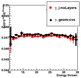
Figure 2: Shower shapes
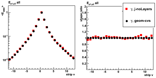
Adding new laters (spacer, front, back)
Figure 3: Sampling fraction vs. thrown energy (left), 2x1/3x3 energy ratio (right)
See legend for details
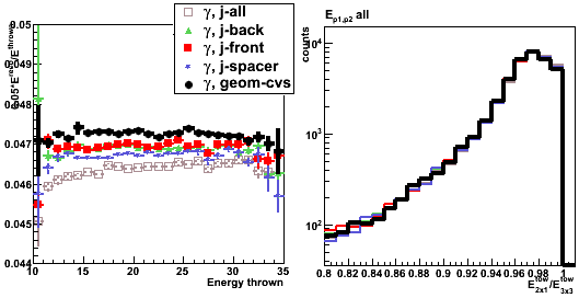
Figure 4: Shower shapes. See legend for details
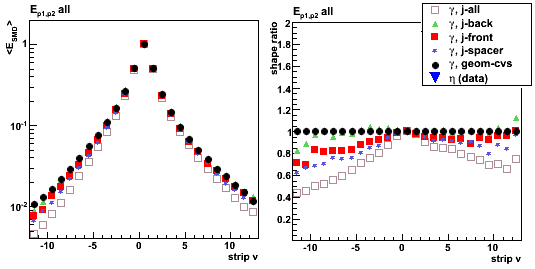
Shower shapes sorted by pre-shower energy
Pre-shower bins:
- Ep1 = 0, Ep2 = 0 (no energy in both EEMC pre-shower layers)
- Ep1 = 0, Ep2 > 0
- 0 < Ep1 < 4 MeV
- 4 < Ep1 < 10 MeV
- Ep1 > 10 MeV
- All pre-shower bins combined
Ep1/Ep2 is the energy deposited in the 1st/2nd EEMC pre-shower layer.
For a single particle MC it is a sum over
all pre-shower tiles in the EEMC with energy of 3 sigma above pedestal.
For eta-meson from pp2006 data the sum is over 3x3 tower patch
Figure 5: Shower shapes (left) and their ratio (right)
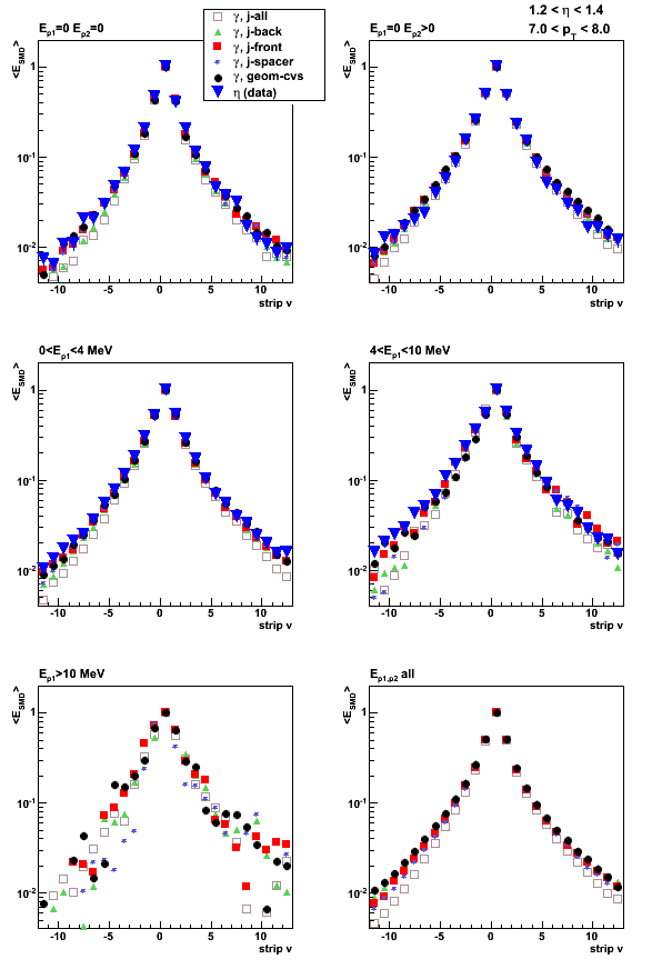
Figure 6: Shower shape ratios
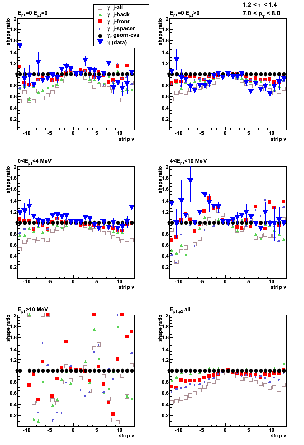
2009.10.13 Jason EEMC geometry: position correlations
Effect of added layers in Jason geometry file (ecalgeo.g23)
Monte-Carlo setup:
- One photon per event
- EEMC only geometry with LOW_EM option
- Throw particles flat in eta (1.08, 2.0), phi (0, 2pi), and pt (6-10 GeV)
- Using A2Emaker to get reconstructed Tower/SMD energy
(no EEMC SlowSimulator in chain) - Vertex z=0
- ~50K/per particle type
- Non-zero energy: 3 sigma above pedestal
Added layer definition from Jason file:
- EXPS is the plastic spacer in the shower maximum section
- EBLS is the layer of material on the back (routing layers) of the SMD planes
- EFLS is the layer of material on the front (G10, etc) of the SMD planes
Geometry configurations and notations (shown in the center of the plot):
- j-noLayers: Jason geometry: no EXPS, EBLS, EFLS
- j-back: Jason geometry, EBLS only
- j-front: Jason geometry, EFLS only
- j-spacer: Jason geometry, EXPS only
- j-all: Jason geometry, all new layers included
- geom-cvs geometry file from CVS after cAir bug fixed
cross section of 1st SMD plane labeled with "SUV" ordering
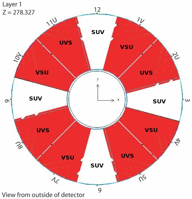
Note: u-v ordering scheme can be found here (Fig. 9-11)
Figure 1: Average number of SMD u-strip fired vs. thrown photon's (x,y)

Figure 2:Average number of SMD v-strip fired vs. thrown photon's (x,y)

Figure 3:Average SMD u-energy vs. thrown photon's (x,y)
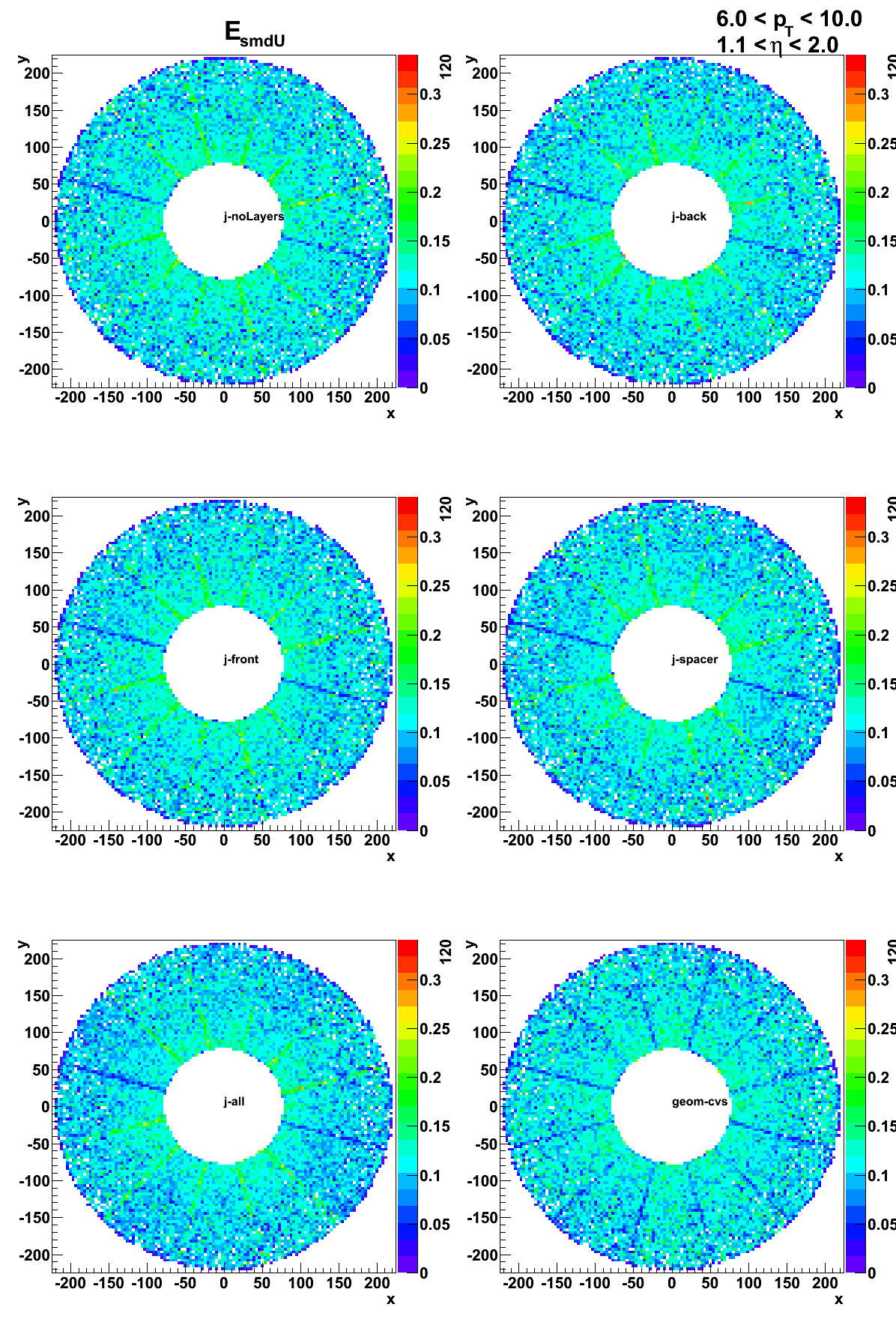
Figure 4:Average SMD v-energy vs. thrown photon's (x,y)
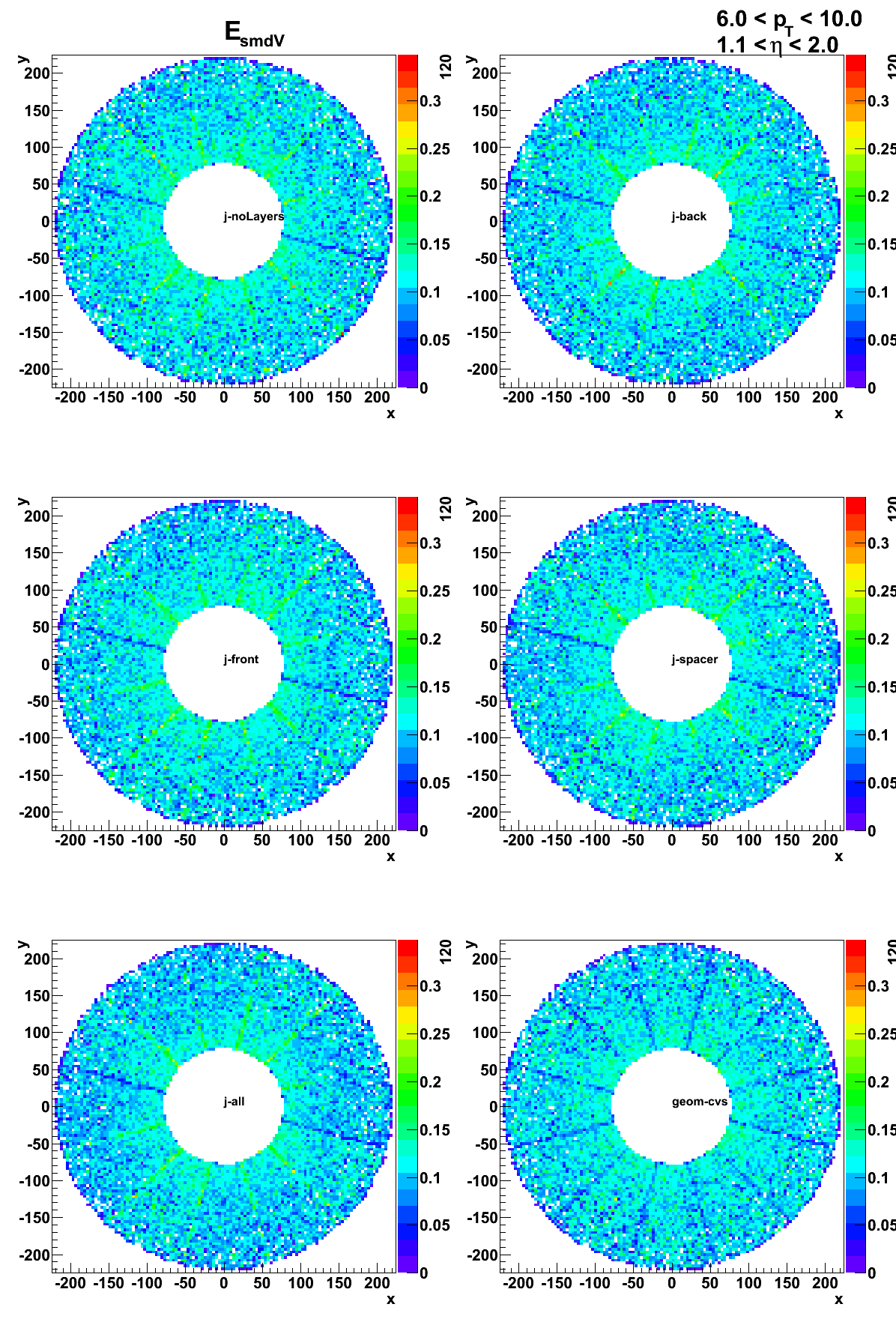
2009.10.16 Jason geometry file: Full STAR simulations
Monte-Carlo setup:
- One photon per event
- EEMC only and Full STAR geometry configurations with LOW_EM option
(using Victor's geometry fix) - Throw particles flat in eta (1.08, 2.0), phi (0, 2pi), and pt (6-10 GeV)
- Using A2Emaker to get reconstructed Tower/SMD energy
(no EEMC SlowSimulator in chain) - Vertex z=0
- ~50K/per particle type
- Non-zero energy: 3 sigma above pedestal
Geometry configurations and notations (shown in the center of the plot):
- eemc-cvs: EEMC only with geometry file from CVS (cAir-fixed)
- full-cvs: Full STAR with geometry file from CVS (cAir-fixed)
- eemc-j: EEMC only with Jason geometry file
- full-j: Full STAR with Jason geometry file
Figure 1: Sampling fraction
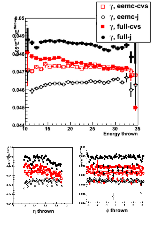
Figure 2: Total energy distribution
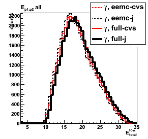
Figure 3: Shower shapes (left) and shape ratios (right) for 0 < pre-shower1 < 4MeV
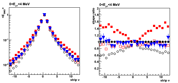
Pre-shower sorted shapes (for completeness)
Figure 4: Shower shapes (all pre-shower bins)
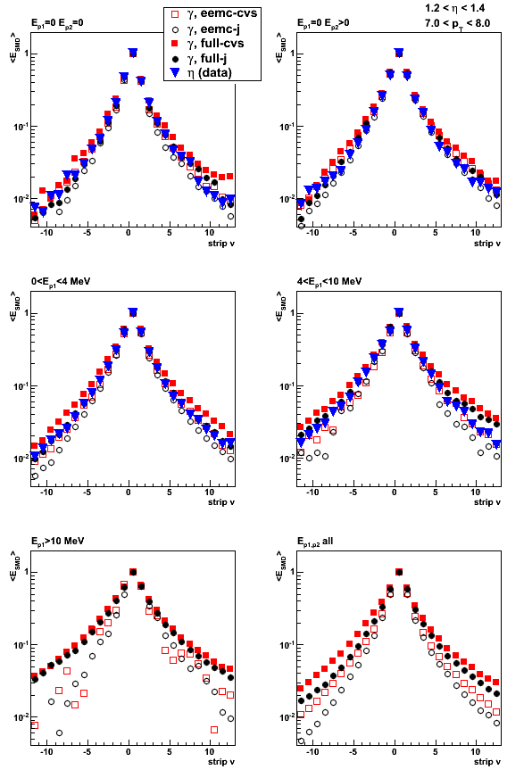
Figure 5: Shower shapes ratio (all pre-shower bins)
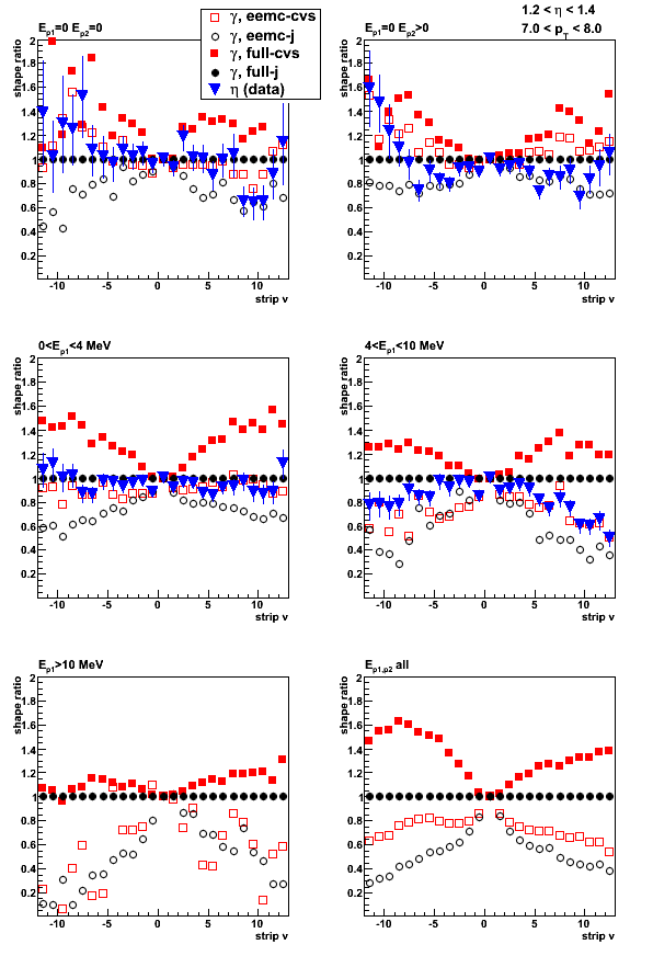
2009.10.20 Sampling fraction problem: full STAr vs. EEMC stand alone geometry
For the previous study click here
Monte-Carlo setup:
- One photon per event
- EEMC only and Full STAR geometry configurations with LOW_EM option
(using Victor's geometry fix) - Throw particles flat in eta (1.08, 2.0), phi (0, 2pi), and pt (6-10 GeV)
- Using A2Emaker to get reconstructed Tower/SMD energy
(no EEMC SlowSimulator in chain) - Vertex z=0
- ~50K/per particle type
- Non-zero energy: 3 sigma above pedestal
Geometry configurations and notations (shown in the center of the plot):
- eemc-cvs: EEMC only with geometry file from CVS (cAir-fixed)
- full-cvs: Full STAR with geometry file from CVS (cAir-fixed)
- eemc-j: EEMC only with Jason geometry file
- full-j: Full STAR with Jason geometry file
Figure 1: Average energy in SMD-u plane vs. position of the thrown photon

SMD v (left) and u (right) sampling fraction (E_smd/E_thrown) vs. E_thrown
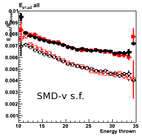
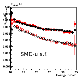
Figure 2: Sampling fraction (E_tower^total/E_thrown) vs. position of the thrown photon
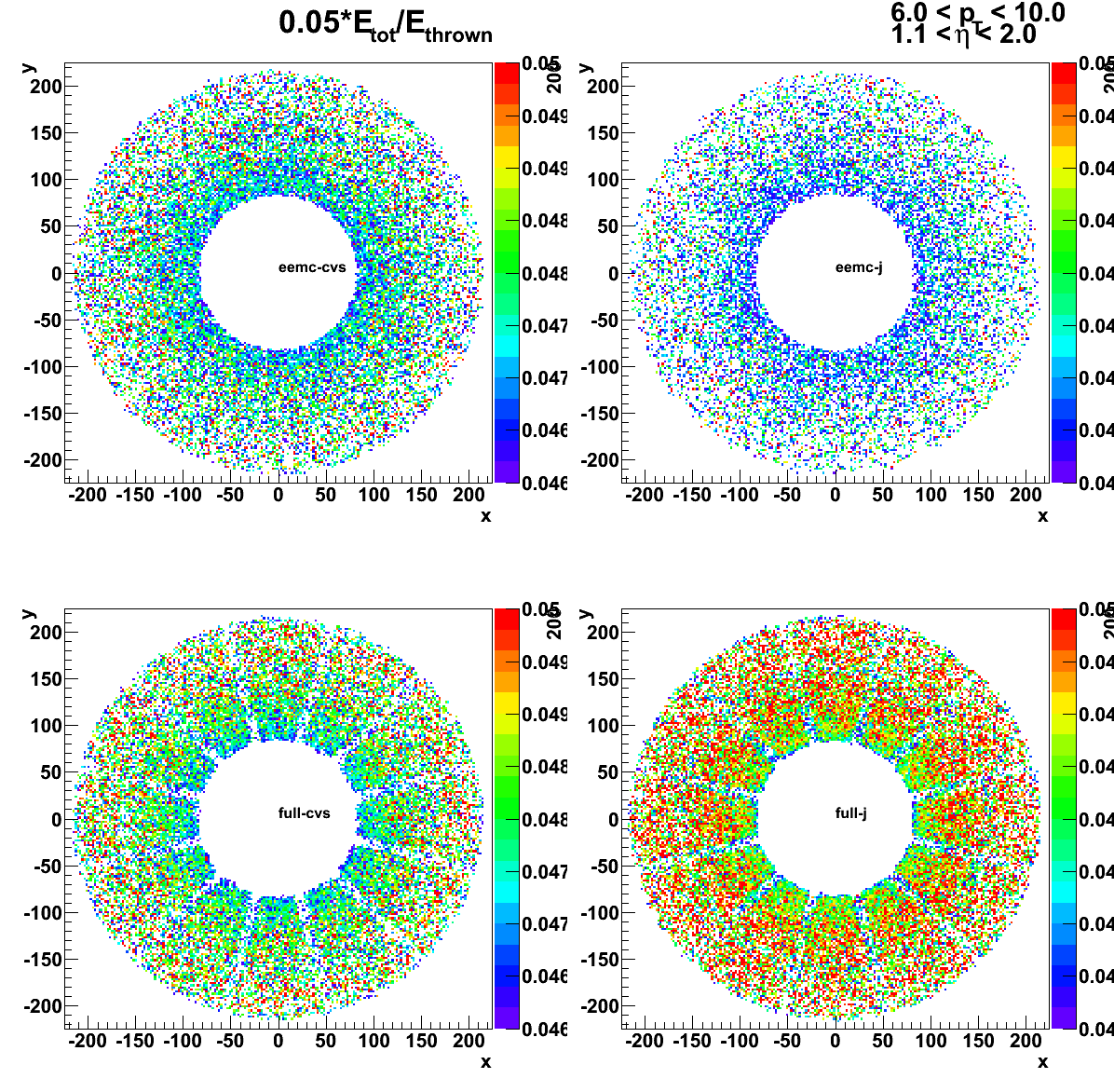
Sampling fraction (E_tower^total/E_thrown) vs. E_thrown
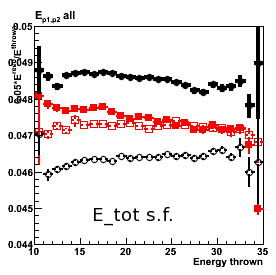
Figure 3: Number of towers above threshold vs. position of the thrown photon
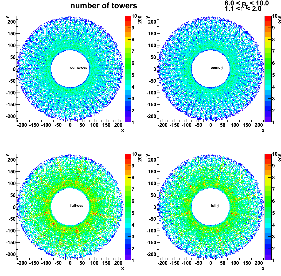
Number of towers above threshold vs. E_thrown
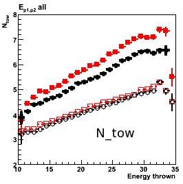
Other EEMC layers: pre-shower, postshower
Figure 4: (left) Pre-shower1 and (right) Pre-shower2 sampling fraction vs. E_thrown
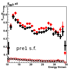
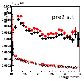
Figure 5: (left) High tower sampling fraction and (right) residual energy, [E_tot-E_3x3]/E_thrown, vs. E_thrown
![]()
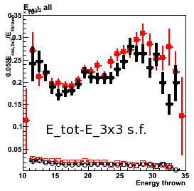
2009.10.26 Jason vs. CVS EEMC: removed SMD layers
Monte-Carlo setup:
- One photon per event
- Disabled new SMD layers (EXPS EBLS EFLS) in Jason geometry
- EEMC only and Full STAR geometry configurations with LOW_EM option
Note: LOW_EM option seems not to work for EEMC only configuration (double checking)
(using Victor's geometry fix) - Throw particles flat in eta (1.08, 2.0), phi (0, 2pi), and pt (6-10 GeV)
- Using A2Emaker to get reconstructed Tower/SMD energy
(no EEMC SlowSimulator in chain) - Vertex z=0
- ~50K/per particle type
- Non-zero energy: 3 sigma above pedestal
Geometry configurations and notations (shown in the center of the plot):
- eemc-cvs: EEMC only with geometry file from CVS (cAir-fixed)
- full-cvs: Full STAR with geometry file from CVS (cAir-fixed)
- eemc-j-noL: EEMC only with Jason geometry file (disabled 3-new SMD layers)
- full-j-noL: Full STAR with Jason geometry file (disabled 3-new SMD layers)
Figure 1: number of post-shower tiles
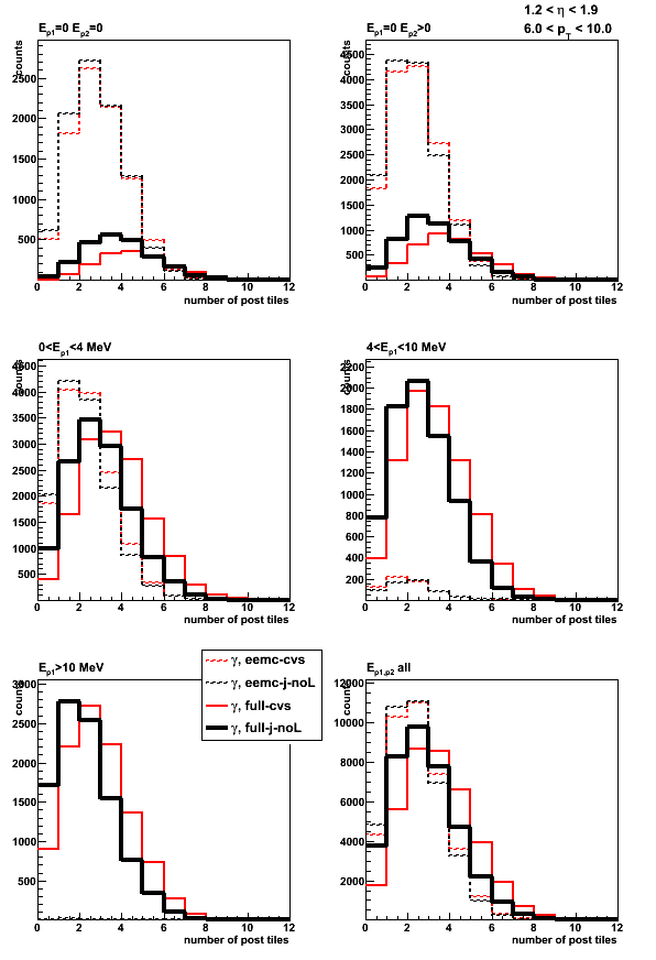
Figure 2: number of pre-1-shower tiles
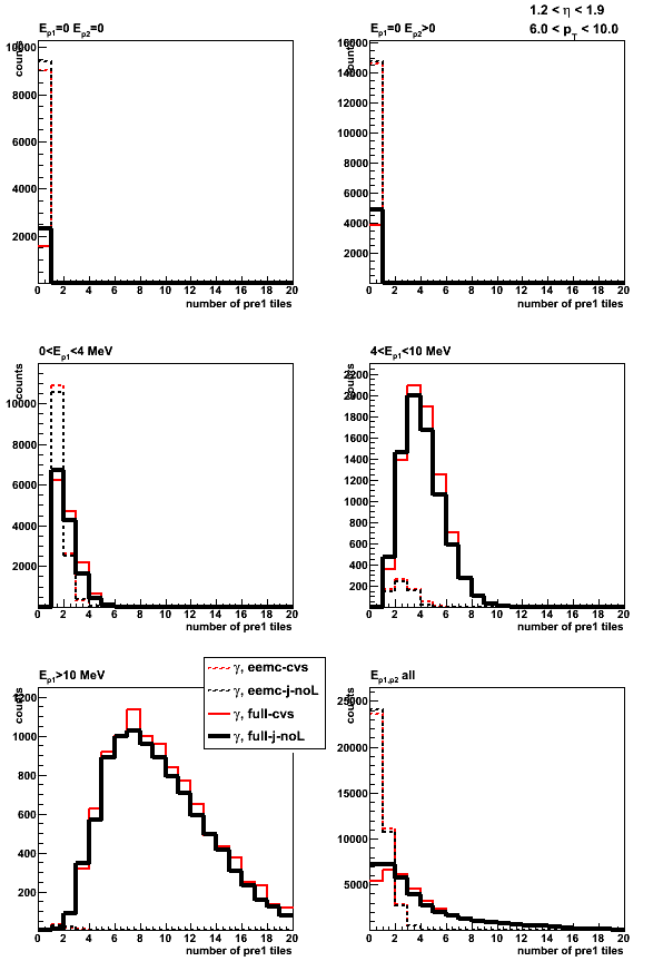
Figure 3: number of pre-2-shower tiles
Figure 4: number of towers
2D
Figure 5: Average pre-shower1 energy
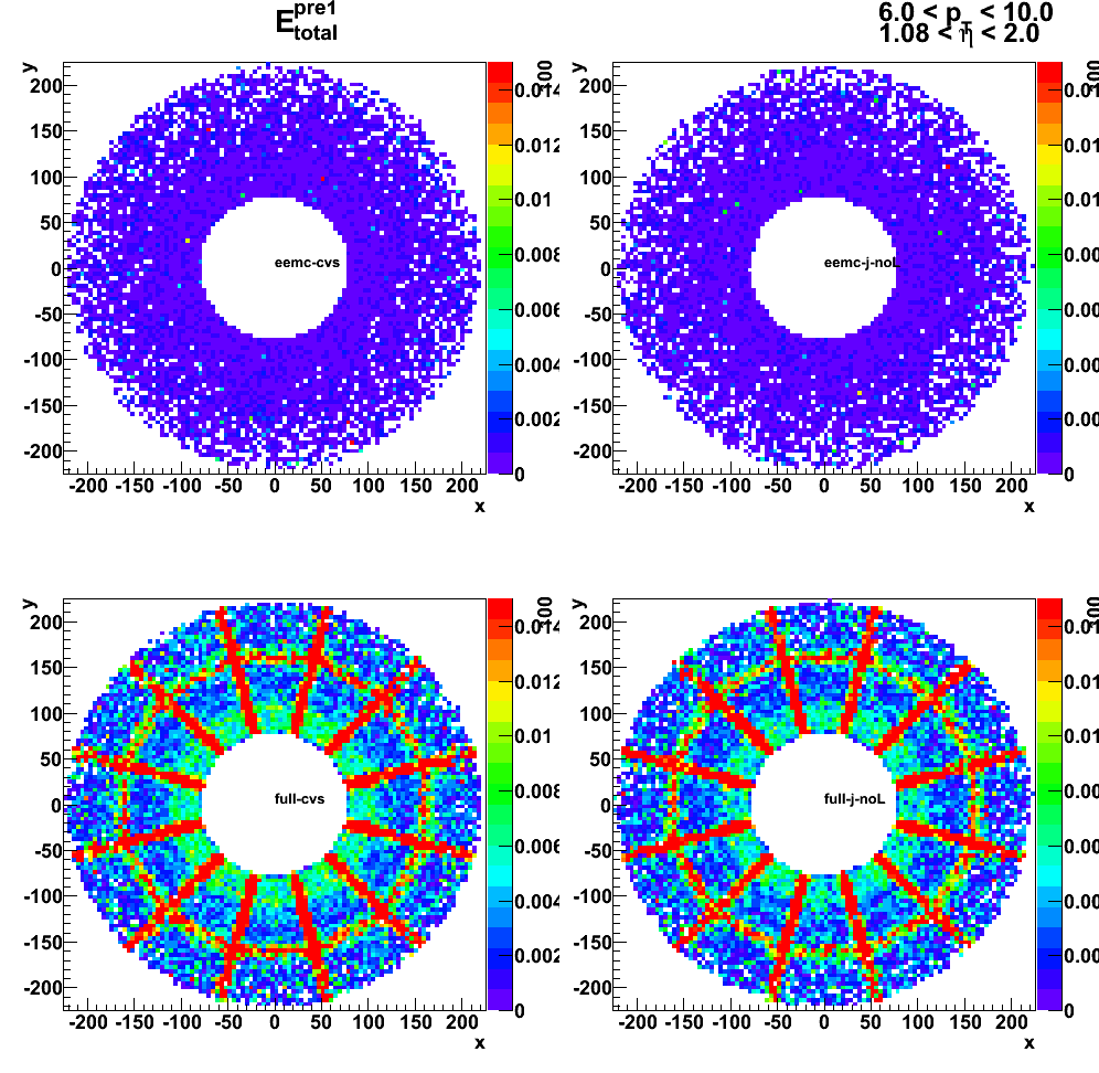
Figure 6: Average pre-shower2 energy
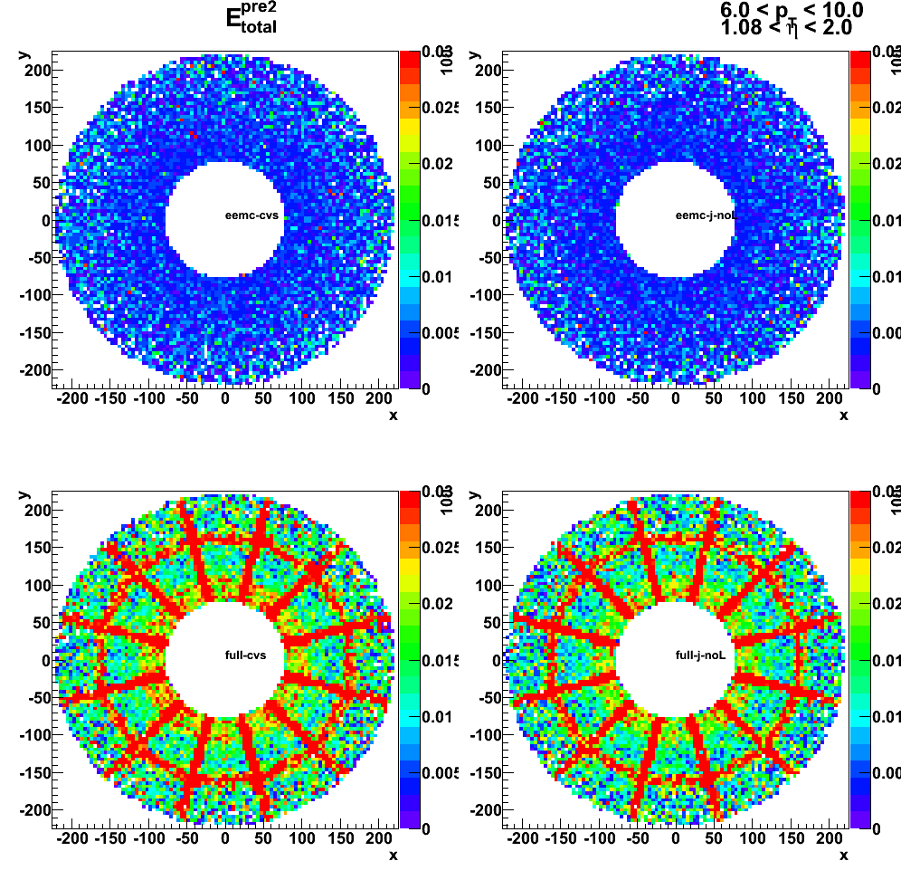
Figure 7: Average number of SMD-u strips

Figure 8: Average number of SMD-v strips
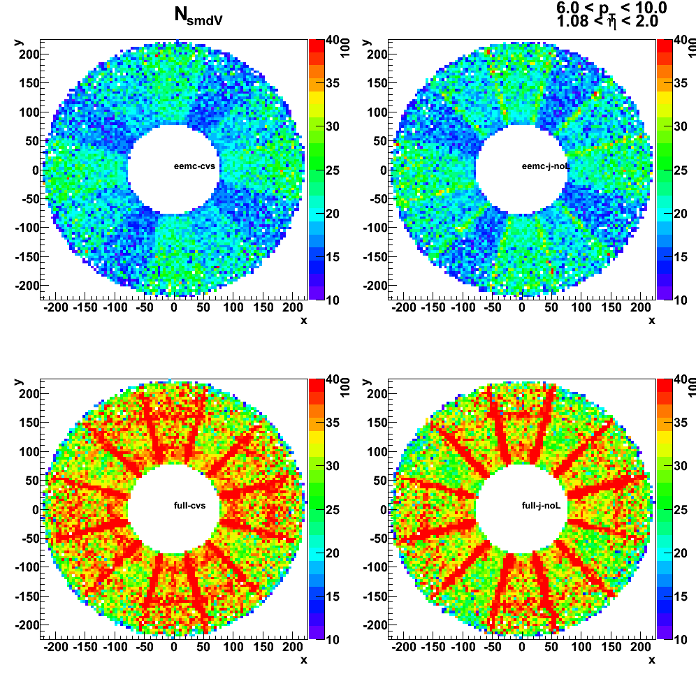
Figure 9: Average post-shower energy
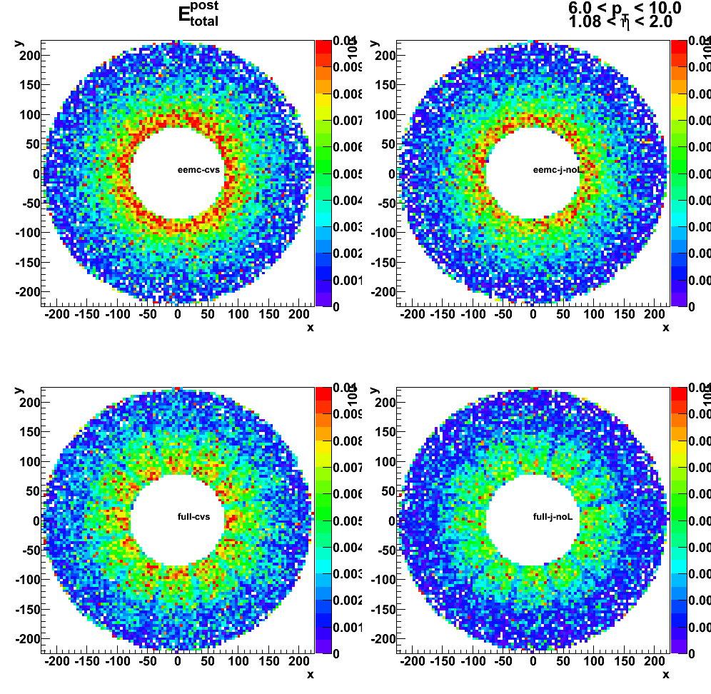
Sampling fraction
Figure 10: Sampling fraction 1x1 vs. thrown energy
![]()
Figure 11: Sampling fraction 2x1 vs. thrown energy
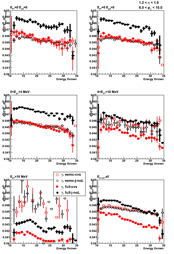
Figure 12: Sampling fraction 3x3 vs. thrown energy

Figure 13: Sampling fraction (total energy) vs. thrown energy
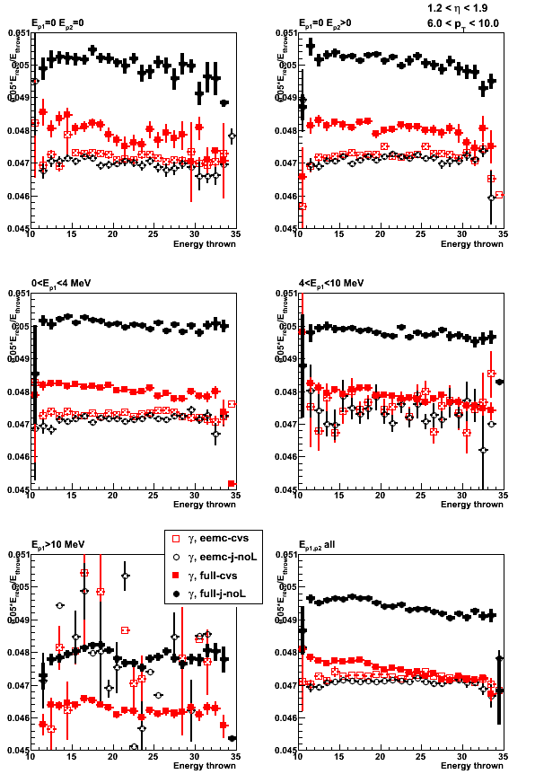
Figure 14: Sampling fraction 1x1
![]()
Figure 15: Sampling fraction 2x1
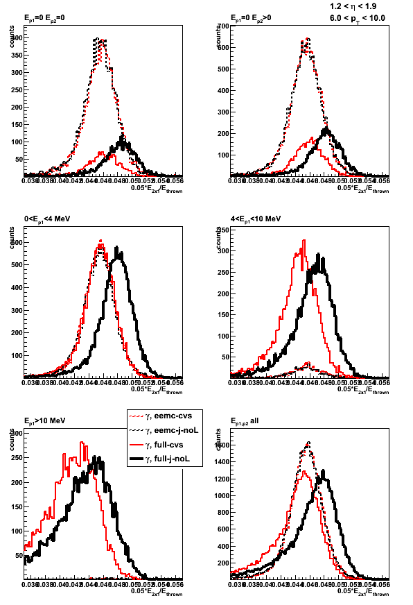
Figure 16: Sampling fraction 3x3

SMD shower shapes
Figure 17: SMD shower shape (v-plane)
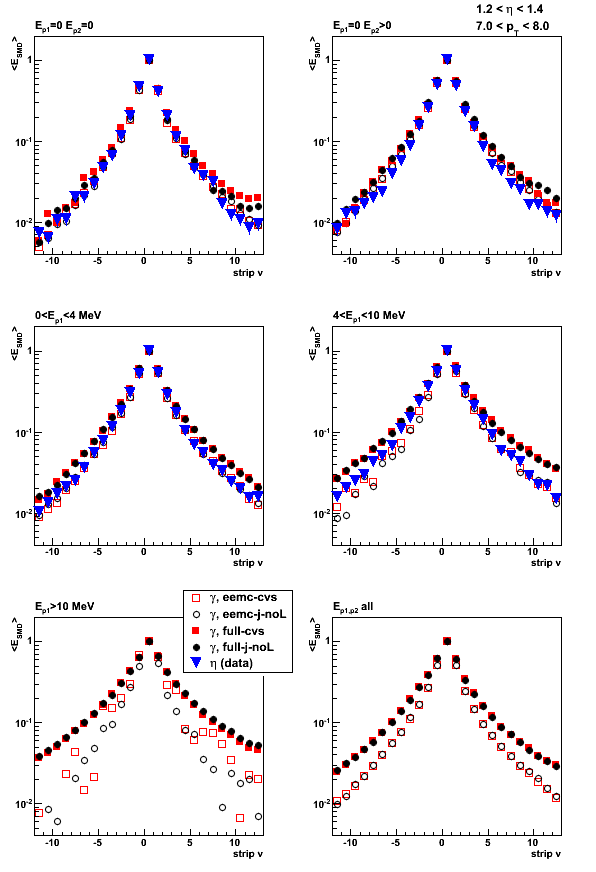
2009.10.27 Jason EEMC geometry: effect of removing new SMD layers
Monte-Carlo setup:
- One photon per event
- Disabled/Enabled new SMD layers (EXPS EBLS EFLS) in Jason geometry
- EEMC only and Full STAR geometry configurations with LOW_EM option
(using Victor's geometry fix) - Throw particles flat in eta (1.08, 2.0), phi (0, 2pi), and pt (6-10 GeV)
- Using A2Emaker to get reconstructed Tower/SMD energy
(no EEMC SlowSimulator in chain) - Vertex z=0
- ~50K/per particle type
- Non-zero energy: 3 sigma above pedestal
Geometry configurations and notations (shown in the center of the plot):
- eemc-j: EEMC only with Jason geometry file
- full-j: Full STAR with Jason geometry file
- eemc-j-noL: EEMC only with Jason geometry file (disabled 3-new SMD layers)
- full-j-noL: Full STAR with Jason geometry file (disabled 3-new SMD layers)
Effect of removing SMD layers on SMD strips
Figure 1: Average number of SMD-u strips
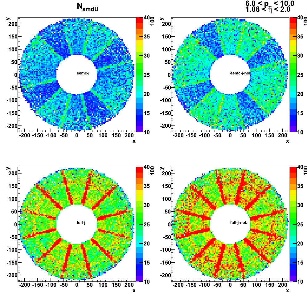
Figure 2: Average number of SMD-v strips
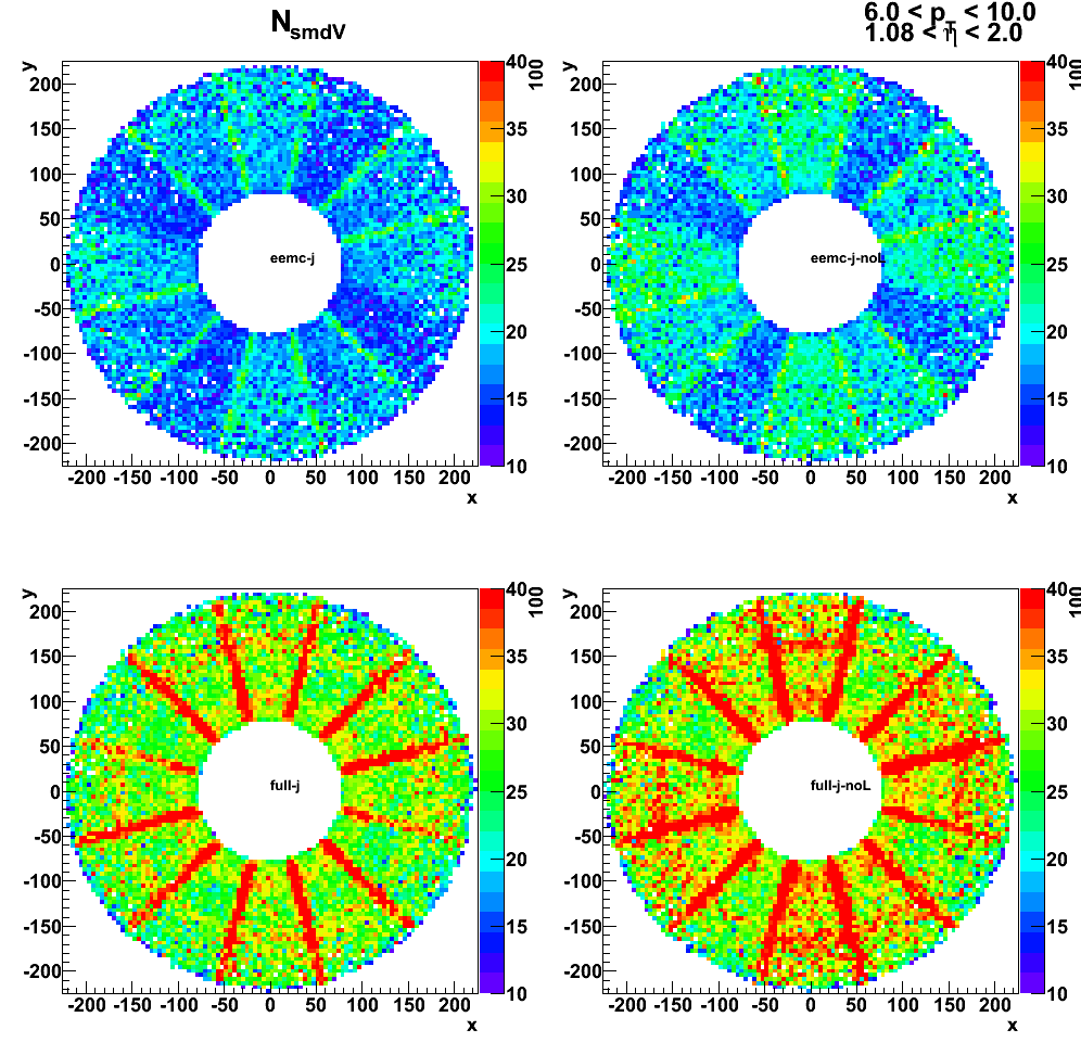
Effect of removing SMD layers on sampling fraction
Figure 3: distribution of 1x1 sampling fraction
![]()
Figure 4: distribution of 2x1 sampling fraction
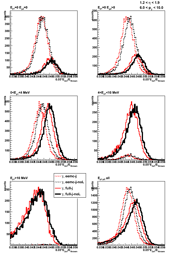
Figure 5: distribution of 3x3 sampling fraction

Figure 6: 1x1 sampling fraction vs. thrown energy
![]()
Figure 7: 2x1 sampling fraction vs. thrown energy
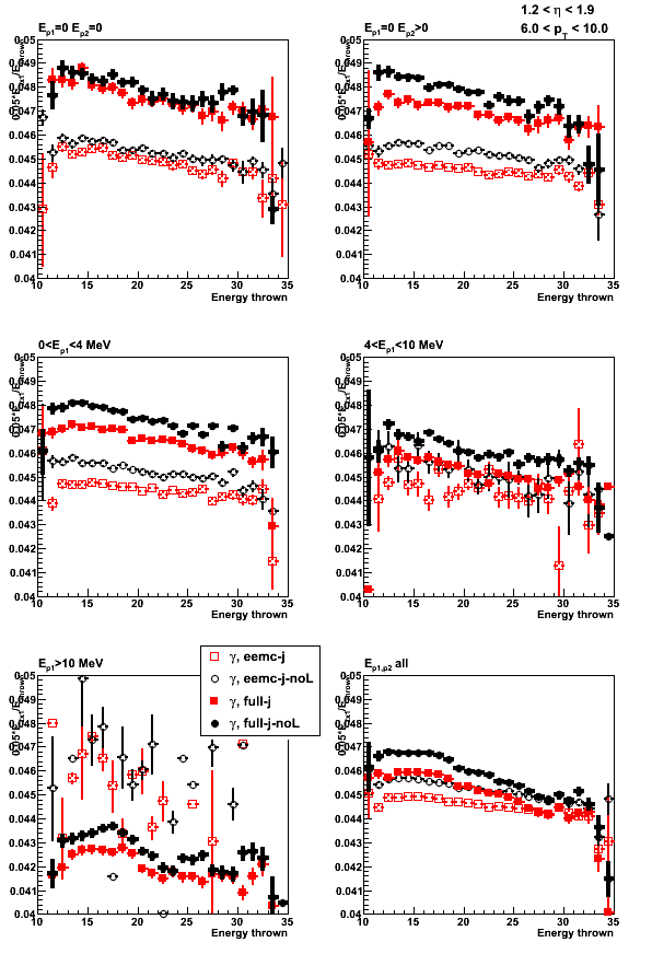
Figure 8: 3x3 sampling fraction vs. thrown energy
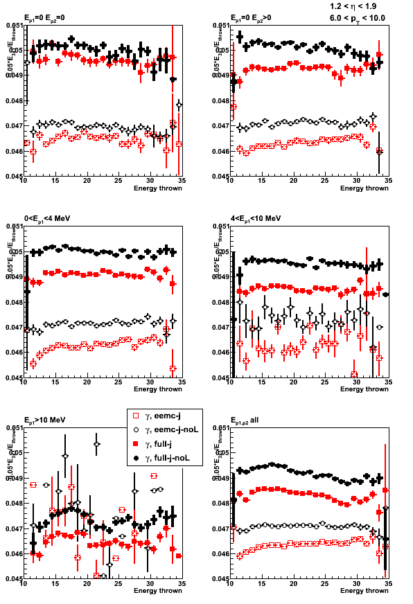
2009.10.27: Jason EEMC geometry: comparison without LOW_EM option
Monte-Carlo setup:
- One photon per event
- Disabled new SMD layers (EXPS EBLS EFLS) in Jason geometry
- EEMC only and Full STAR geometry configurations without LOW_EM option
(using Victor's geometry fix) - Throw particles flat in eta (1.08, 2.0), phi (0, 2pi), and pt (6-10 GeV)
- Using A2Emaker to get reconstructed Tower/SMD energy
(no EEMC SlowSimulator in chain) - Vertex z=0
- ~50K/per particle type
- Non-zero energy: 3 sigma above pedestal
Geometry configurations and notations (shown in the center of the plot):
- eemc-cvs: EEMC only with geometry file from CVS (cAir-fixed)
- full-cvs: Full STAR with geometry file from CVS (cAir-fixed)
- eemc-j-noL: EEMC only with Jason geometry file (disabled 3-new SMD layers)
- full-j-noL: Full STAR with Jason geometry file (disabled 3-new SMD layers)
Figure 1: Sampling fraction 1x1
![]()
Figure 2: Sampling fraction 2x1
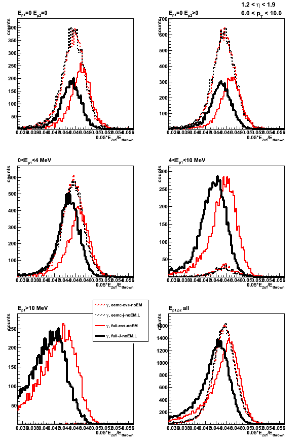
Figure 3: Sampling fraction 3x3
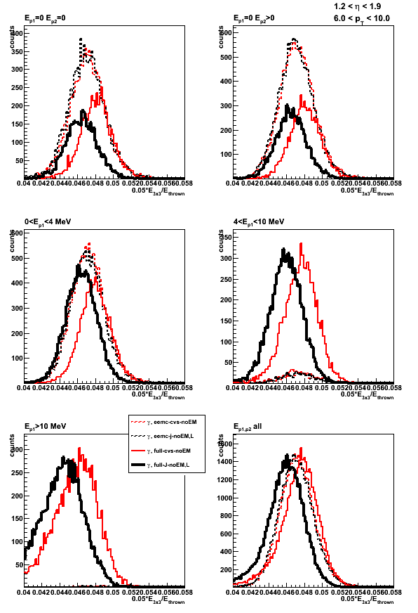
Figure 4: Sampling fraction total energy
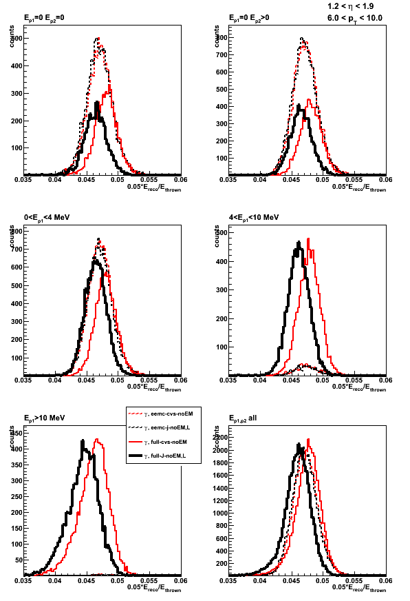
Figure 5: Sampling fraction pre1-shower
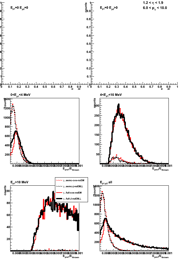
Figure 6: Sampling fraction pre2-shower

Figure 7: Sampling fraction smd-u
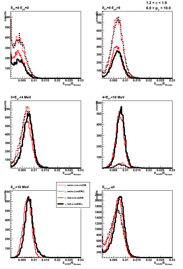
Figure 8: Sampling fraction smd-v
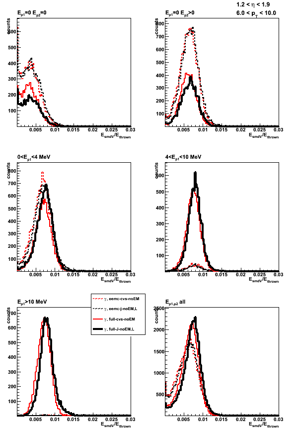
Figure 9: Sampling fraction post-shower
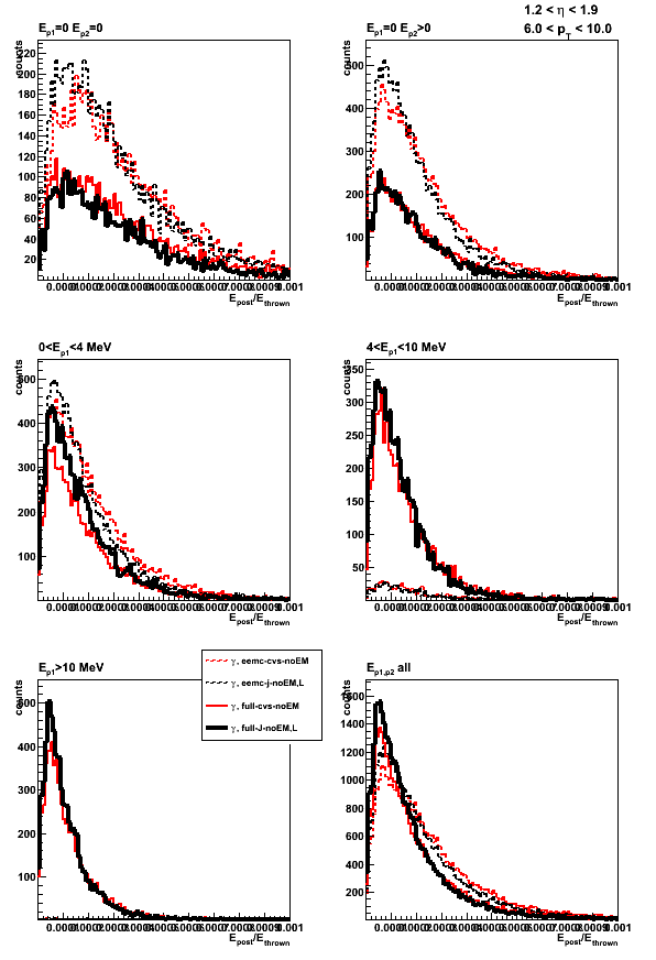
Sampling fraction vs. thrown energy
Figure 10: Sampling fraction 1x1 vs. thrown energy
![]()
Figure 11: Sampling fraction 2x1 vs. thrown energy
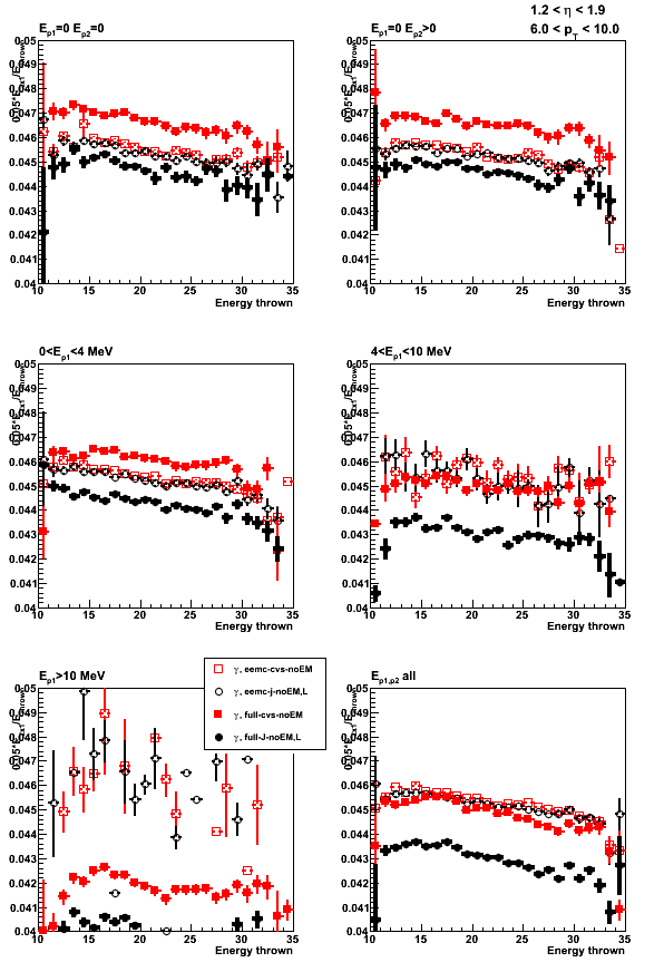
Figure 12: Sampling fraction 3x3 vs. thrown energy
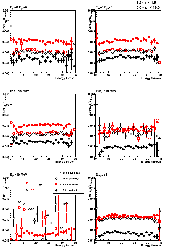
Figure 13: Sampling fraction (tatal energy) vs. thrown energy
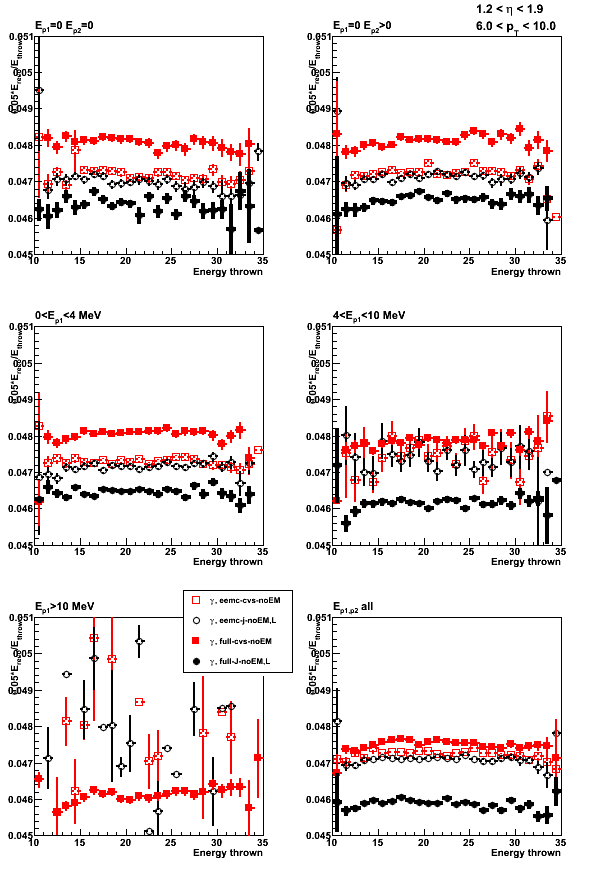
2009.10.30: Jason EEMC geometry: Jason with ELED block from CVS file
FYI: Alice blog on ELED block study
Monte-Carlo setup:
- One photon per event
- Disabled SMD layers (EXPS EBLS EFLS) in Jason geometry
- Put ELED block from CVS file into Jason geometry
geometry configurations without LOW_EM option
(using Victor's geometry fix)- Throw particles flat in eta (1.08, 2.0), phi (0, 2pi), and pt (6-10 GeV)
- Using A2Emaker to get reconstructed Tower/SMD energy
(no EEMC SlowSimulator in chain) - Vertex z=0
- ~50K/per particle type
- Non-zero energy: 3 sigma above pedestal
Geometry configurations and notations (shown in the center of the plot):
- full-cvs: Full STAR with geometry file from CVS (cAir-fixed)
- full-j: EEMC only with Jason geometry file (disabled 3-new SMD layers, ELED block replaced with that from CVS)
Figure 1: Sampling fraction 1x1 (up-left), 2x1 (up-right), 3x3 (low-left), total energy (low-right)
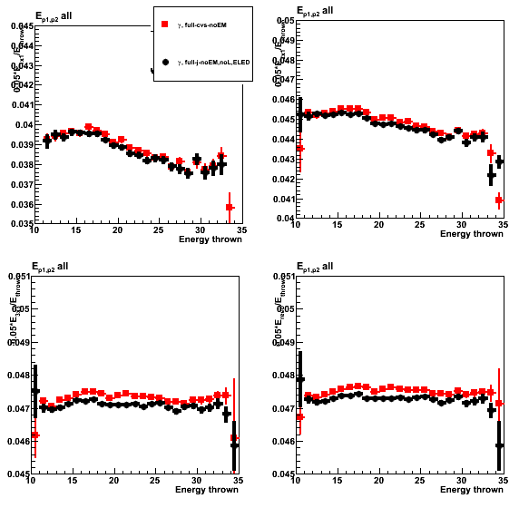
Figure 2: Sampling fraction pre1 (up-left), pre2 (up-right), SMD-u (low-left), post (low-right)

Figure 3: Shower shapes (left) and shower shape ratio (right)

11 Nov
November 2009 posts
2009.11.02 Jason EEMC geometry: results with and without LOW_EM options
Monte-Carlo setup:
- One photon per event
- Disabled SMD layers (EXPS EBLS EFLS) in Jason geometry
geometry configurations with and without LOW_EM option
(using Victor's geometry fix)- Throw particles flat in eta (1.08, 2.0), phi (0, 2pi), and pt (6-10 GeV)
- Using A2Emaker to get reconstructed Tower/SMD energy
(no EEMC SlowSimulator in chain) - Vertex z=0
- ~50K/per particle type
- Non-zero energy: 3 sigma above pedestal
Geometry configurations and notations (shown in the center of the plot):
- full-cvs-noEM (dashed): CVS geometry (cAir-fixed) without LOW_EM option
- full-cvs-EM (solid): CVS geometry (cAir-fixed) with LOW_EM option
- full-j-NoEM-noL: Jason geometry (disabled 3-new SMD layers) without LOW_EM option
- full-j-EM-noL: Jason geometry (disabled 3-new SMD layers) with LOW_EM option
Figure 1: Distribution of the sampling fraction (total energy in EEMC)
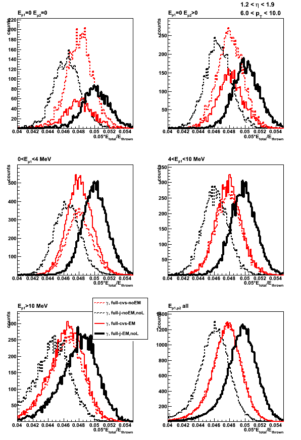
Figure 2: Sampling fraction (total energy in EEMC) vs. thrown energy

Figure 3: Sampling fraction (total energy in EEMC) vs. position of the thrown photon
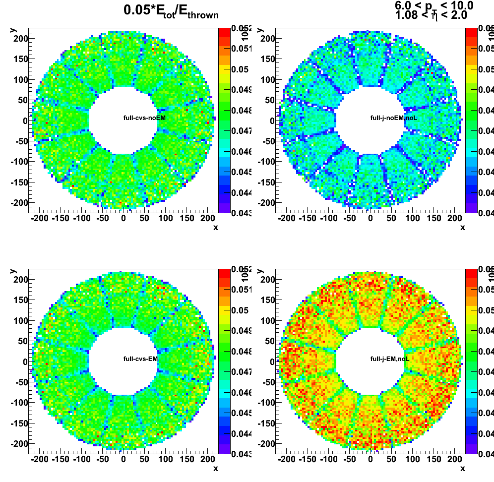
2009.11.03 BEMC sampling fraction: with and without LOW_EM option
Monte-Carlo setup:
- Throwing one photon per event
- Full STAR geometry (y2006g) configurations with and without LOW_EM option.
Note: LOW_EM cuts are listed at the bottom of this page,
and some related discussion can be found in this phana thread - Throw particles flat in eta (-1,1), phi (0, 2pi), and energy (30 +/- 0.5 GeV)
- Vertex z=0
- 50K/per particle type
Geometry configurations and notations:
- BEMC-noLOW_EM: Full STAR y2006g without LOW_EM option
- BEMC-LOW_EM: Full STAR y2006g with LOW_EM option
data base settings (same settings in bfc.C (Jan's trick) and in my MuDst reader):
dbMk->SetFlavor("sim","bemcPed");
dbMk->SetFlavor("Wbose","bemcCalib");
dbMk->SetFlavor("sim","bemcGain");
dbMk->SetFlavor("sim","bemcStatus");
dbMk->SetFlavor("sim","bprsPed");
dbMk->SetFlavor("Wbose","bprsCalib");
dbMk->SetFlavor("sim","bprsGain");
dbMk->SetFlavor("sim","bprsStatus");
dbMk->SetFlavor("sim","bsmdePed");
dbMk->SetFlavor("Wbose","bsmdeCalib");
dbMk->SetFlavor("sim","bsmdeGain");
dbMk->SetFlavor("sim","bsmdeStatus");
dbMk->SetFlavor("sim","bsmdpPed");
dbMk->SetFlavor("Wbose","bsmdpCalib");
dbMk->SetFlavor("sim","bsmdpGain");
dbMk->SetFlavor("sim","bsmdpStatus");
Note: for BEMC ideal pedSigma set to 0, so effectively
there is no effect when I apply 3-sigma threshold above pedestal.
Figure 1: E_reco/E_thrown distribution.
E_reco is the total energy in the BEMC towers from mMuDstMaker->muDst()->muEmcCollection()
E_thrown energy of the thrown photon from tne GEant record
No cut (yet) applied to exclude otliers in the average
Outliers in E_reco/E_thrown
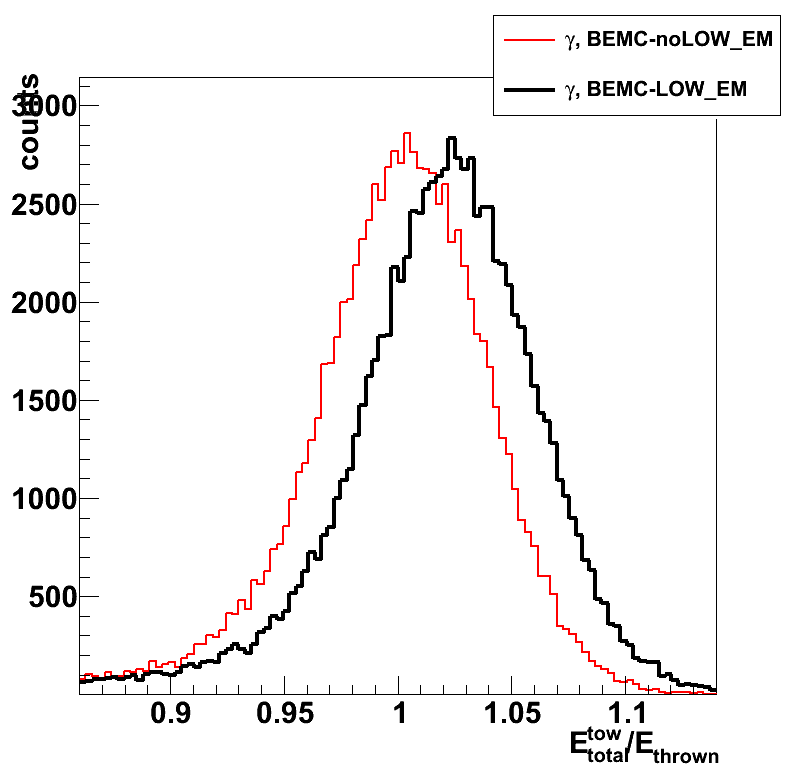
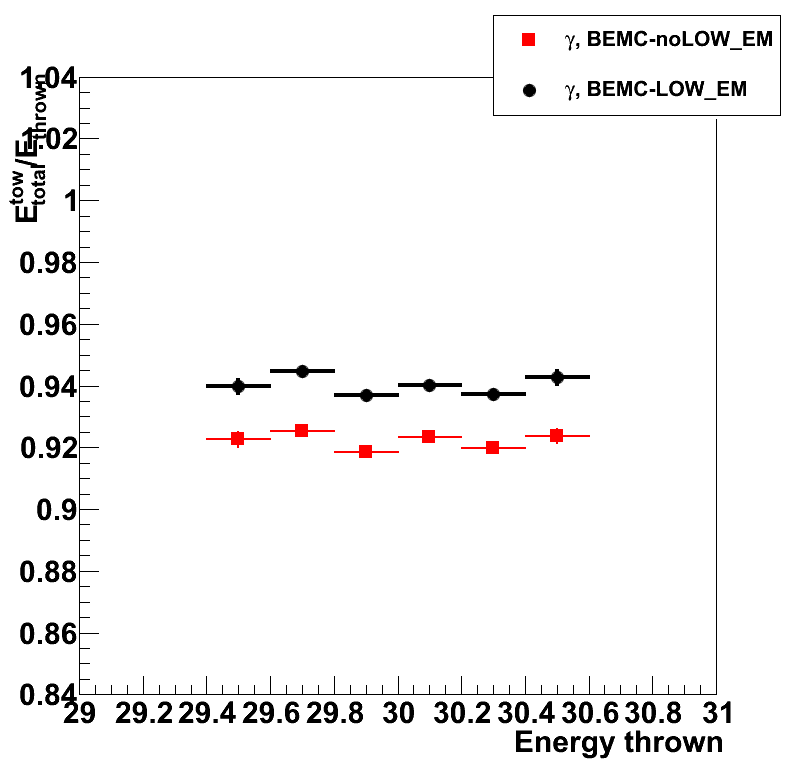
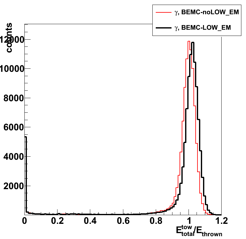
Figure 2: Average E_reco/E_thrown vs. thrown photon eta (left) and phi (right)
Average is taken over a slice in eta or phi (no gaussian fits)
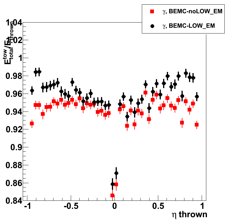
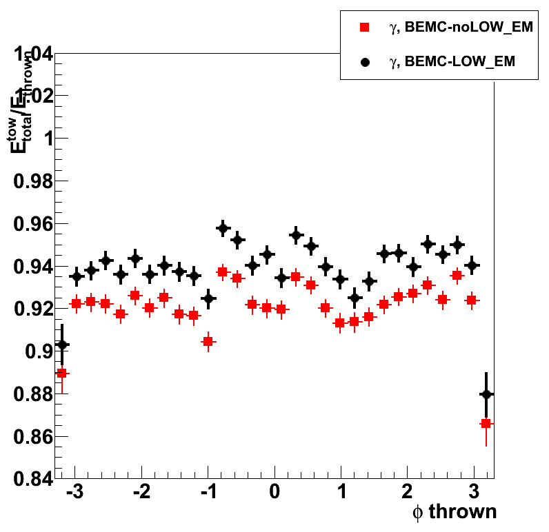
Figure 3: Average E_reco/E_thrown vs. thrown position (eta and phi)
Left: without LOW_EM option; right: with LOW_EM option
No cut applied to exclude otliers
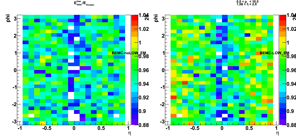
2009.11.03 Jason EEMC geometry: Effect of ELED block change
Monte-Carlo setup:
- One photon per event
- Disabled SMD layers (EXPS EBLS EFLS) in Jason geometry
- Alter the ELED block (lead absorber plate) in Jason geometry file
- Full STAR geometry configurations with and without LOW_EM option
(using Victor's geometry fix) - Throw particles flat in eta (1.08, 2.0), phi (0, 2pi), and pt (6-10 GeV)
- Using A2Emaker to get reconstructed Tower/SMD energy
(no EEMC SlowSimulator in chain) - Vertex z=0
- ~50K/per particle type
- Non-zero energy: 3 sigma above pedestal
Figure 1: Sampling fraction (total energy in EEMC)
- Solid symbols and lines present results with LOW_EM option
Note: the black are the same in left and right plots - Open/dashed symbols and lines - results without LOW_EM option
- Upper plots - distribution of the sampling fcation
- Lower plots - Sampling fcation vs. thrown photon energy
- Left plots: CVS geometry vs. Jason with removed extra SMD layers.
ELED block is the same in all 4 cases, and is taken from CVS file.
in red: CVS geometry, in black - Jason geometry - Right plots:
Jason with new ELED block (in red) vs. Jason with ELED block from CVS (in black)
Extra SMD layers are removed in all 4 cases

Figure 2: Sampling fraction (total energy in EEMC)
black: same black as in Fig. 1, upper plots
red: EEMC geometry with Material PbAlloy isvol=0
(modification suggested by Jason in this post)
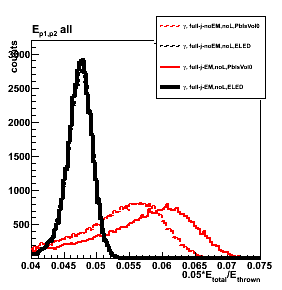
2009.11.06 new EEMC geometry: Pure lead and new SMD layers
Monte-Carlo setup:
- One photon per event
- Disabled/Enabled SMD layers (EXPS EBLS EFLS) in Jason geometry
- Alter the ELED block with pure lead
- Full STAR geometry configurations with and without LOW_EM option
(using Victor's geometry fix) - Throw particles flat in eta (1.08, 2.0), phi (0, 2pi), and pt (6-10 GeV)
- Using A2Emaker to get reconstructed Tower/SMD energy
(no EEMC SlowSimulator in chain) - Vertex z=0
- ~50K/per particle type
- Non-zero energy: 3 sigma above pedestal
Geometry configurations
- dashed/open red (j-noEM,noL,Pb):
full STAR y2006, no LOW_EM, Jason EEMC geometry without new SMD layers, pure lead in ELED block - solid red (j-EM,noL,Pb):
full STAR y2006, LOW_EM, Jason EEMC geometry without new SMD layers, pure lead in ELED block - dashed/open black (j-noEM,Pb):
full STAR y2006, no LOW_EM, Jason EEMC geometry with new SMD layers, pure lead in ELED block - solid black (j-EM,Pb):
full STAR y2006, LOW_EM, Jason EEMC geometry with new SMD layers, pure lead in ELED block
Sampling fraction of various EEMC layers (tower, SMD, pre1-,pre2-, post- shower)
Figure 1: Tower sampling fraction distribution
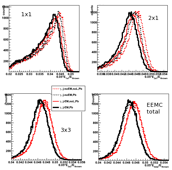
Figure 2: Tower sampling fraction vs. thrown energy
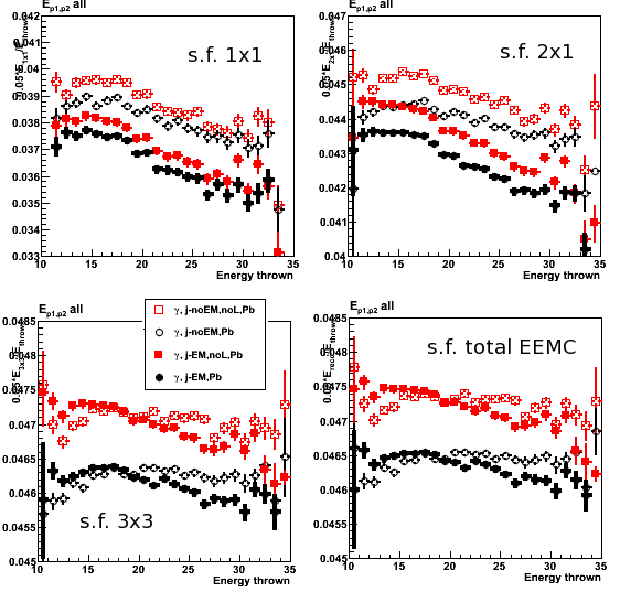
Figure 3: Tower sampling fraction vs. position of the thrown photon
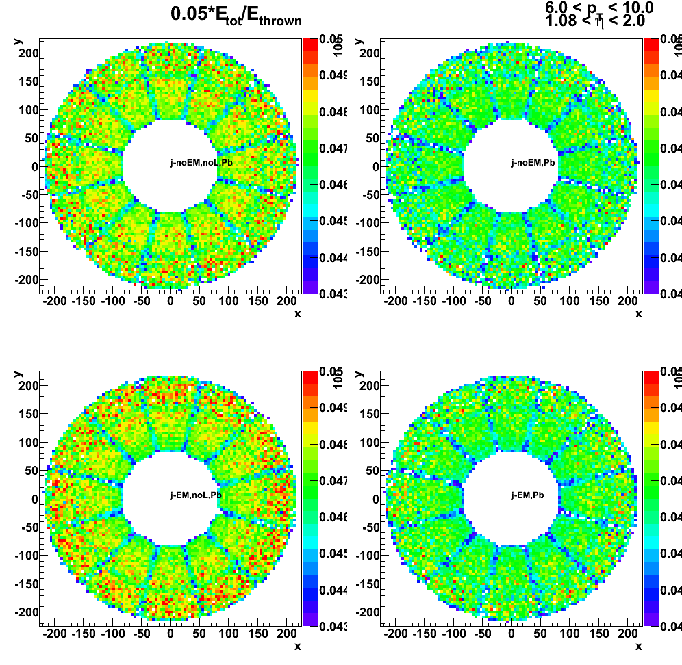
Figure 4: Pre1, pre2, post and SMD sampling fraction distribution
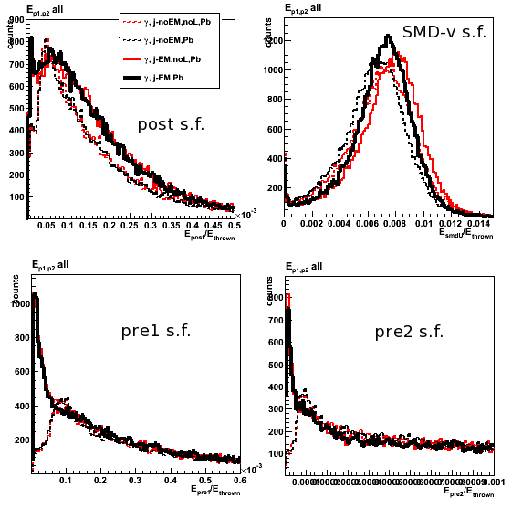
Figure 5: Pre1, pre2, post and SMD sampling fraction vs. thrown energy
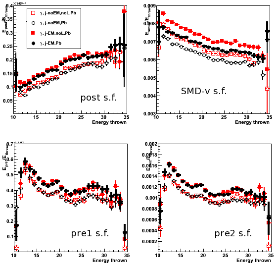
SMD shower shapes
Figure 6: SMD-v shower shapes

Figure 7: SMD-v shower shape ratios
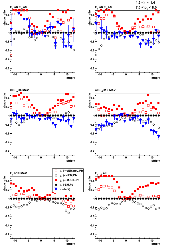
Figure 8: Number of SMD-u strips

Figure 9: Number of SMD-v strips
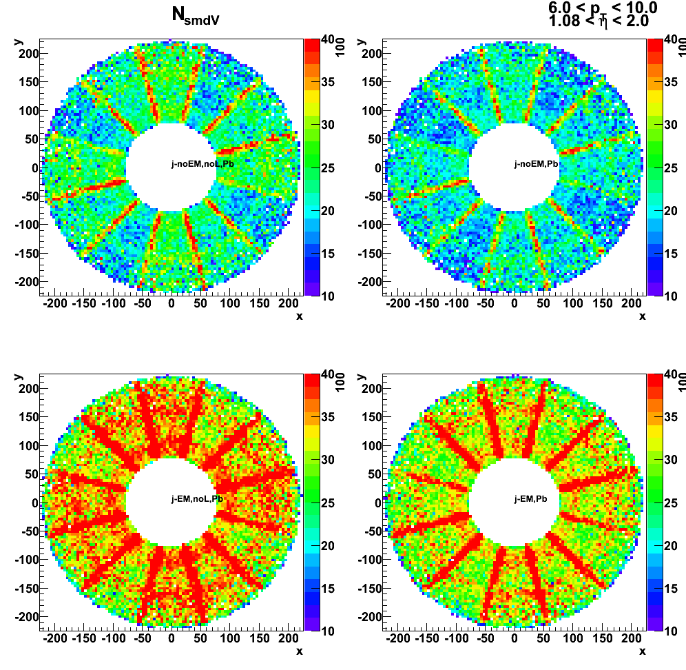
Tower energy profile
Figure 10: Energy ractio of 2x1 to 3x3 cluster vs. gamma-jet data
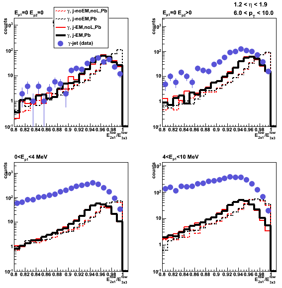
Energy deposition in various EEMC layers vs. position of the thrown photon
Figure 11: Pre-shower1 energy
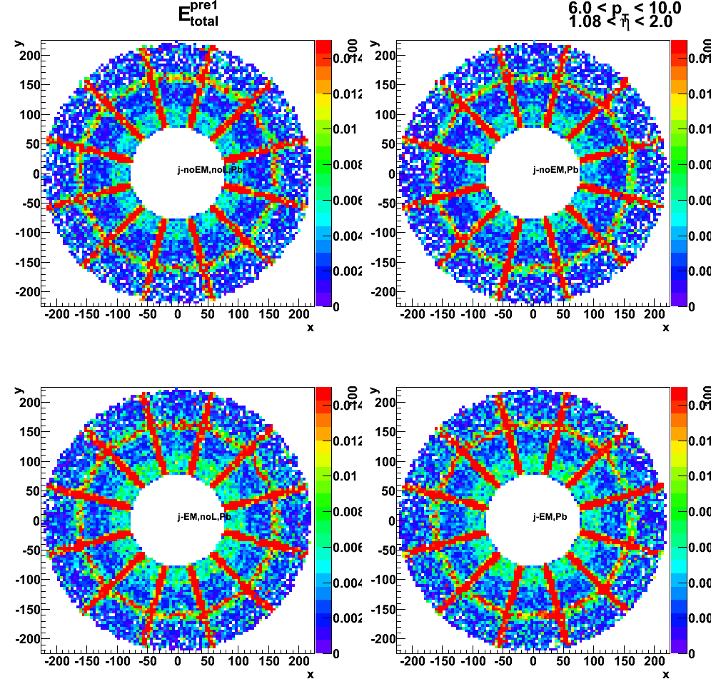
Figure 12: Pre-shower2 energy
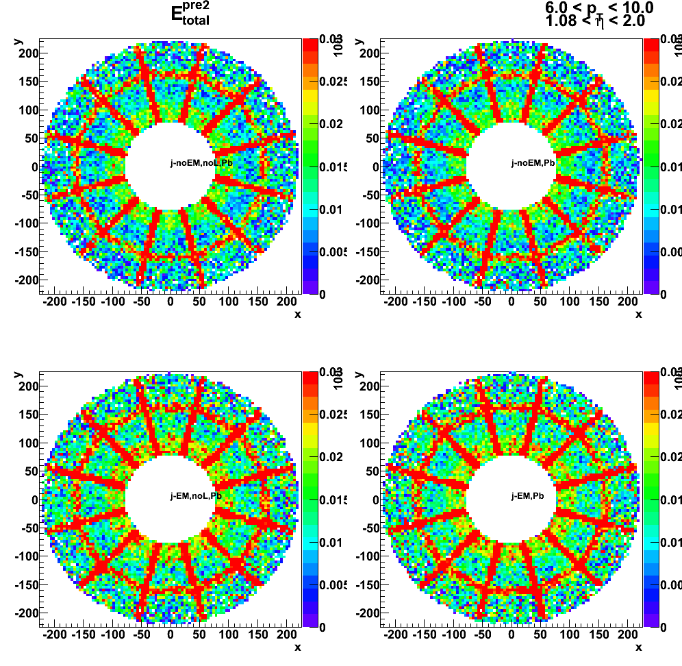
Figure 13: Post-shower energy
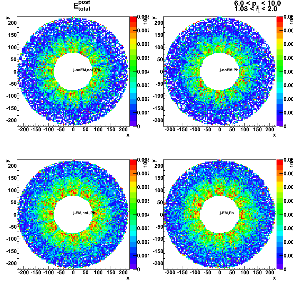
Figure 14: SMD-v energy
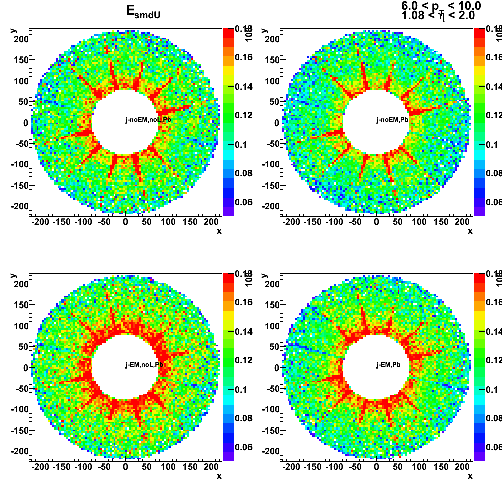
Figure 15: Number of towers
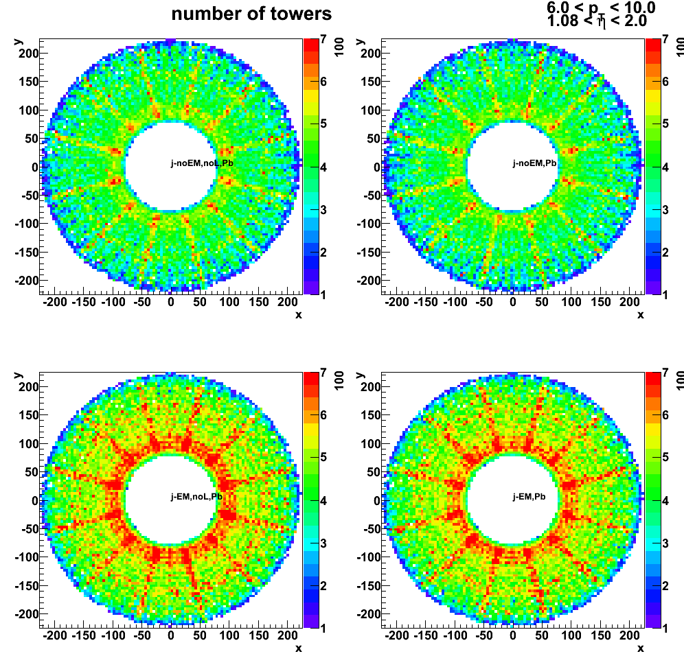
LOW_EM option and pre-shower migration
Figure 16: Tower Sampling fraction: LOW_EM option and pre-shower migration
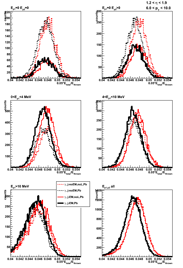
2009.11.10 BEMC sampling fraction and clustering
Monte-Carlo setup:
- Throwing one photon per event
- Full y2009 STAR geometry configurations with and without LOW_EM option.
Note: LOW_EM cuts are listed at the bottom of this page,
and some related discussion can be found in this phana thread - Throw particles flat in eta (-0.95,0.05) amd (0.05, 0.95), phi (0, 2pi), and energy (30 +/- 0.5 GeV)
- bfc.C options:
trs,fss,y2009,Idst,IAna,l0,tpcI,fcf,ftpc,Tree,logger,ITTF,Sti,MakeEvent,McEvent,
geant,evout,IdTruth,tags,bbcSim,tofsim,emcY2,EEfs,
GeantOut,big,-dstout,fzin,-MiniMcMk,beamLine,clearmem,eemcDB,VFPPVnoCTB - Use fixed (7%) sampling fraction in StEmcSimpleSimulator.cxx
mSF[0] = 1/0.07;
mSF[1] = 0.;
mSF[2] = 0.; - Vertex z=0
- 50K/per particle type
Geometry configurations and notations:
- BEMC-noLOW_EM: Full STAR y2009 without LOW_EM option
- BEMC-LOW_EM: Full STAR y2009 with LOW_EM option
data base settings (same settings in bfc.C (Jan's trick) and in my MuDst reader):
dbMk->SetFlavor("sim","bemcPed");
dbMk->SetFlavor("Wbose","bemcCalib");
dbMk->SetFlavor("sim","bemcGain");
dbMk->SetFlavor("sim","bemcStatus");
Note: for BEMC ideal pedSigma set to 0, so effectively
there is no effect when I apply 3-sigma threshold above pedestal.
Figure 1: Sampling fraction (0.07*E_reco/E_thrown) distribution: average vs. gaussian fit
E_reco is the total energy in the BEMC towers from mMuDstMaker->muDst()->muEmcCollection()
E_thrown energy of the thrown photon from tne GEant record
The difference between fit and using average values is < 0.7%
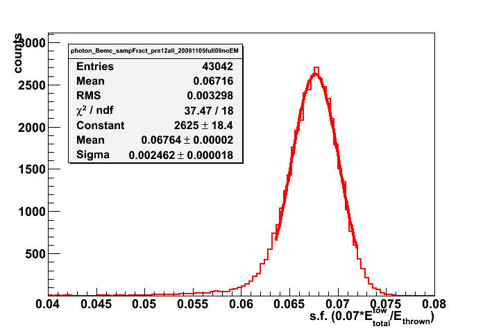
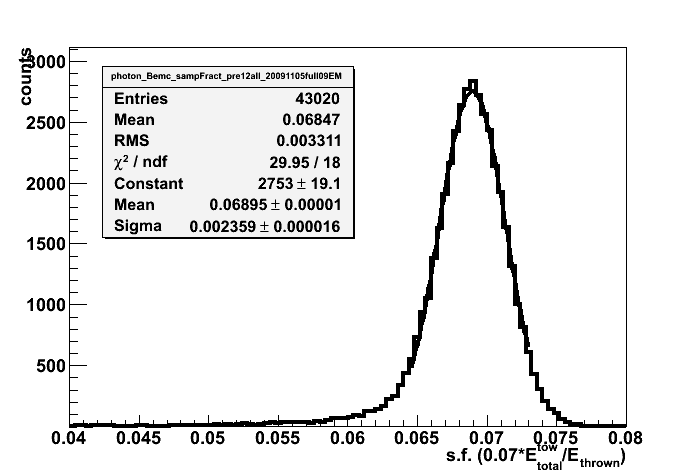
Figure 2: Otliers vs. eta and phi: (left) no energy reconstrycted, (right) s.f. < 55%
Most outlier are at eta = 0, -1, +1

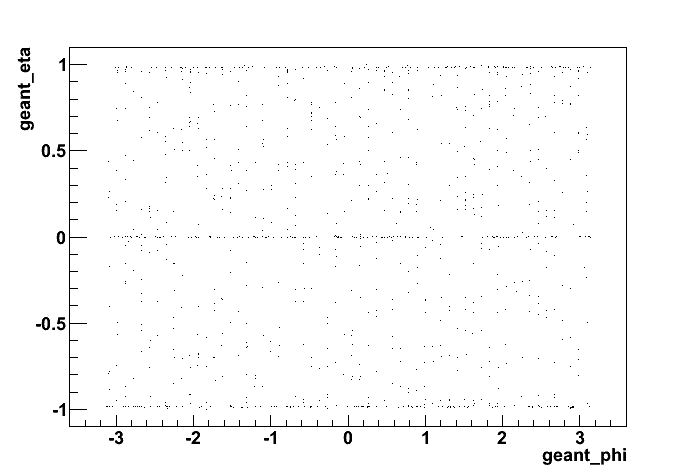
Figure 3: Sampling fraction (0.07*E_reco/E_thrown) distribution
Effect of LOW_EM cuts
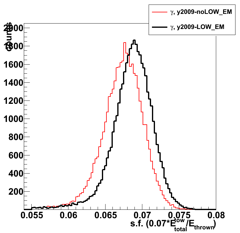

Figure 4: Sampling fraction vs. thrown photon eta (left) and phi (right)
Average is taken over a slice in eta or phi with cut on outliers (events with s.f. < 5.5% rejected)
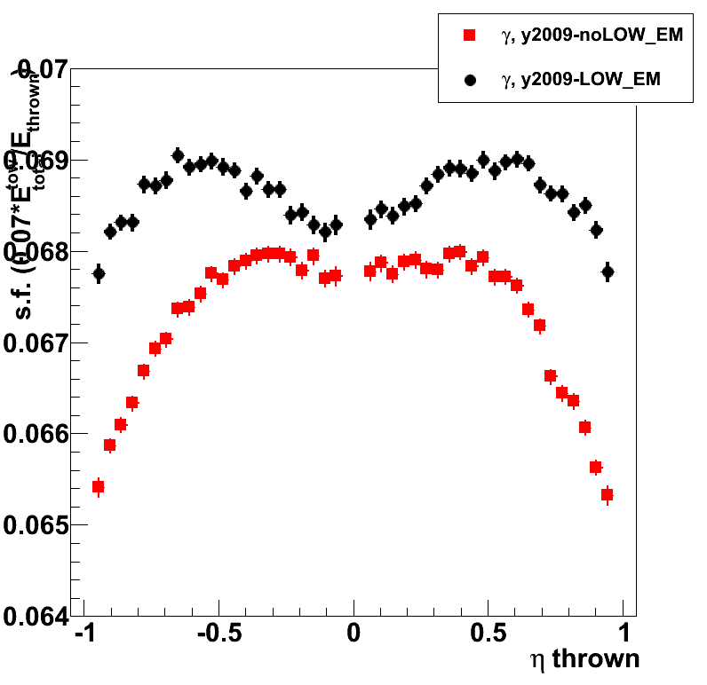

Figure 5: Sampling fraction vs. thrown position (eta and phi)
Average is taken over a slice in eta or phi with cut on outliers (events with s.f. < 5.5% rejected)
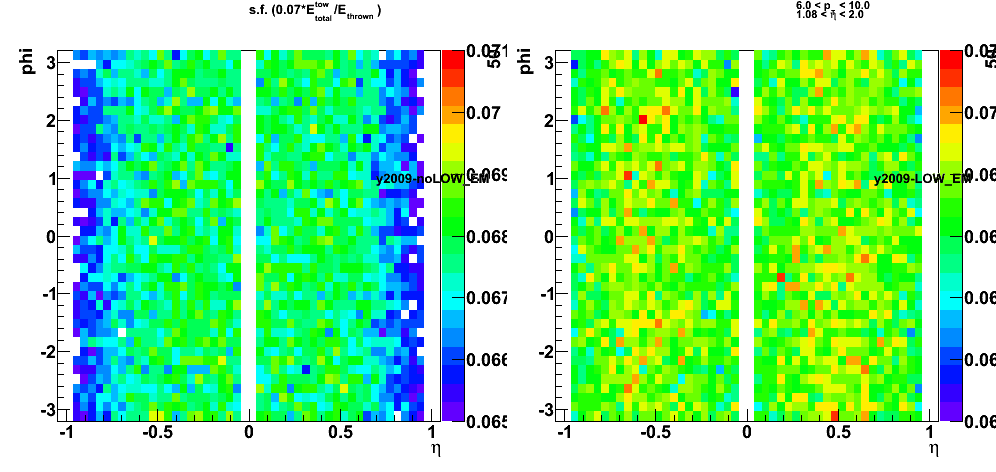
Figure 6: (left) Single tower sampling fraction
and (right) energy ratio of 1x1 cluster to the total BEMC energy
Not much of the effect from LOW_EM cuts on the 1x1 clustering. Need to look at other (2x1, 2x2 clusters)
![]()
![]()
2009.11.11 Tests of EEMC geometry, version 6.1
Monte-Carlo setup:
- Throwing one photon per event
- Compare EEMC geometry v6.0 (pure lead) vs. v6.1
- Full STAR geometry configurations with and without LOW_EM option
- Throw particles flat in eta (1.08, 2.0), phi (0, 2pi), and pt (6-10 GeV)
- Using A2Emaker to get reconstructed Tower/SMD energy (no EEMC SlowSimulator in chain)
- Vertex z=0
- ~50K/per particle type
- Non-zero energy: 3 sigma above pedestal
Geometry configurations
- dashed/open red: full STAR y2006, no LOW_EM, EEMC geometry v6.1
- solid red: full STAR y2006, with LOW_EM, EEMC geometry v6.1
- dashed/open black: full STAR y2006, full STAR y2006, no LOW_EM, EEMC geometry v6.0
- solid black: full STAR y2006, full STAR y2006, with LOW_EM, EEMC geometry v6.0
Sampling fraction of various EEMC layers (tower, SMD, pre1-,pre2-, post- shower)
Figure 1: Sampling fraction of various EEMC layers vs. thrown photon energy:
(a) tower s.f.; (b) tower s.f. distribution; (c) pre-shower1; (d) pre-shower2; (e) SMD, (f) post-shower

Figure 2: (left) Shower shapes and (right) shower shape ratios
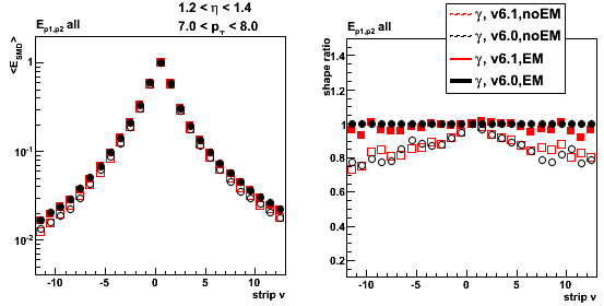
2009.11.16 Tests of EEMC geometry, version 6.1: lead vs. mixture
Monte-Carlo setup:
- Throwing one photon per event
- Compare EEMC geometry v6.1 with pure lead vs. mixture
- Full STAR geometry configurations with and without LOW_EM option
- Throw particles flat in eta (1.08, 2.0), phi (0, 2pi), and pt (6-10 GeV)
- Using A2Emaker to get reconstructed Tower/SMD energy (no EEMC SlowSimulator in chain)
- Vertex z=0
- ~50K/per particle type
- Non-zero energy: 3 sigma above pedestal
Geometry configurations
- dashed/open red: full STAR y2006, no LOW_EM, EEMC geometry v6.1 with pure lead
- solid red: full STAR y2006, with LOW_EM, EEMC geometry v6.1 with pure lead
- dashed/open black: full STAR y2006, full STAR y2006, no LOW_EM, EEMC geometry v6.1 with lead-ally mixture
- solid black: full STAR y2006, full STAR y2006, with LOW_EM, EEMC geometry v6.1 with lead-ally mixture
Figure 1: EEMC sampling fraction vs. thrown photon energy:
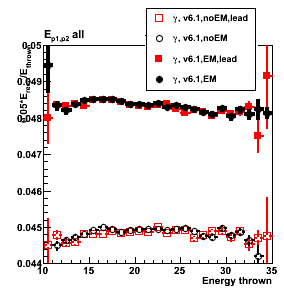
2009.11.17 BEMC sampling fraction: energy dependence
Monte-Carlo setup:
- Throwing one photon per event
- Full y2009 STAR geometry configurations with LOW_EM option
- Throw particles flat in eta (-1,1), phi (0, 2pi),
with energy steps: 10, 20, 30, 40, and 50 GeV with flat (+/-0.5 GeV) spread - bfc.C options:
trs,fss,y2009,Idst,IAna,l0,tpcI,fcf,ftpc,Tree,logger,ITTF,Sti,MakeEvent,McEvent,
geant,evout,IdTruth,tags,bbcSim,tofsim,emcY2,EEfs,
GeantOut,big,-dstout,fzin,-MiniMcMk,beamLine,clearmem,eemcDB,VFPPVnoCTB - Use fixed (7%) sampling fraction in StEmcSimpleSimulator.cxx
mSF[0] = 1/0.07;
mSF[1] = 0.;
mSF[2] = 0.; - Vertex z=0
- 50K/per particle type
data base settings (same settings in bfc.C (Jan's trick) and in my MuDst reader):
dbMk->SetFlavor("sim","bemcPed");
dbMk->SetFlavor("Wbose","bemcCalib");
dbMk->SetFlavor("sim","bemcGain");
dbMk->SetFlavor("sim","bemcStatus");
Note: for BEMC ideal pedSigma set to 0, so effectively
there is no effect when I apply 3-sigma threshold above pedestal.
Figure 1: Rapidity cuts study (no eta cuts, no cuts on otliers in this figure)
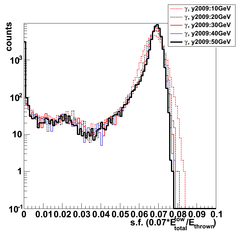
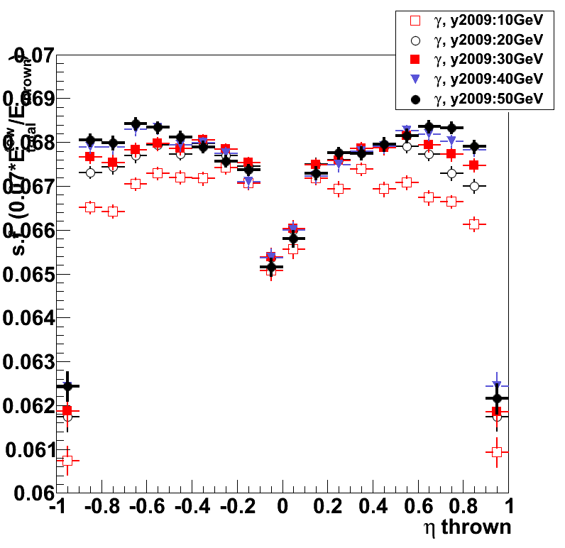


Figure 2: Sampling fraction (0.07*E_reco/E_thrown) distribution
E_reco is the total energy in the BEMC towers from mMuDstMaker->muDst()->muEmcCollection()
E_thrown energy of the thrown photon from tne Geant record
Cuts: |eta| < 0.97 && |eta|>0.01 && s.f. > 0.055
s.f. distribution on the log scale
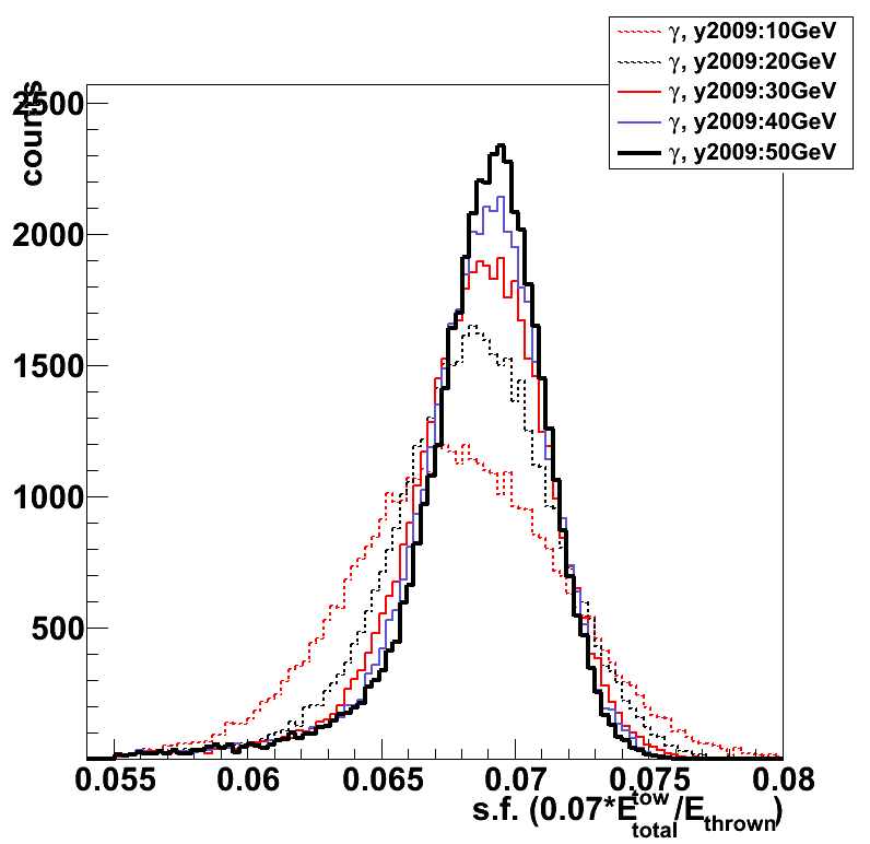

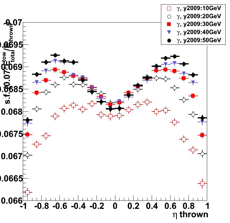
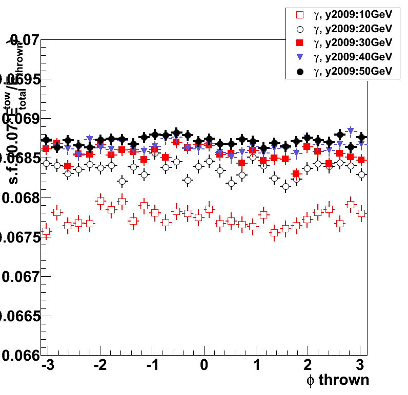
2009.11.19 LOW_EM and EEMC time/event in starsim
Monte-Carlo setup:
- Throwing one photon/electron per event
- y2009 geometry tag (EEMC geometry v6.1)
- Full STAR geometry configurations with and without LOW_EM option
- Throwing particles flat in eta (1.08, 2.0), phi (0, 2pi), and energy (5-35 GeV)
- ~50K/per particle type, 250 events per job, 200 jobs
Geometry configurations
- red: without LOW_EM option
- black: with LOW_EM option
- circles - electrons, squares - photons
Figure 1: (left) time/event distribution, (right) average time for the particle type
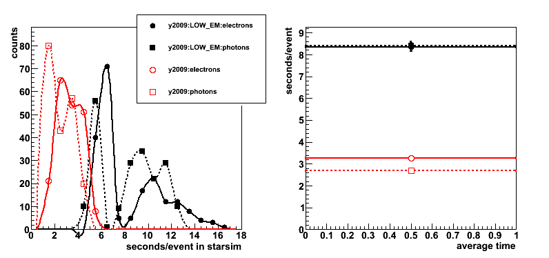
Conclusion: for single particle Monte-Carlo required time in starsim
with LOW_EM option is ~ 2.6 times higher.
2009.11.23 New EEMC geometry (CVS v6.1): y2006 vs. y2009 STAR configurations
Monte-Carlo setup:
- Throwing one photon per event
- Compare new EEMC geometry in CVS for y2006 and 2009 configurations
- Full STAR geometry configurations with and without LOW_EM option
- Throw particles flat in eta (1.08, 2.0), phi (0, 2pi), and energy (5-35 GeV)
- Using A2Emaker to get reconstructed Tower/SMD energy (no EEMC SlowSimulator in chain)
- Vertex z=0
- ~50K/per particle type
- Non-zero energy: 3 sigma above pedestal
Geometry configurations
- red: full STAR y2009, with/without LOW_EM, EEMC geometry
- black: full STAR y2006, with/without LOW_EM, EEMC geometry v6.1
Figure 1: EEMC sampling fraction (left) distribution (right) vs. thrown photon energy (1.2 < eta < 1.9; no pt cuts)
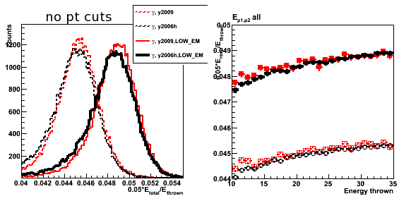
Figure 2: EEMC sampling fraction (left) distribution (right) vs. thrown photon energy (1.2 < eta < 1.9; pt > 7GeV cut)
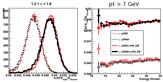
Figure 3: 2x1/3x3 clustering
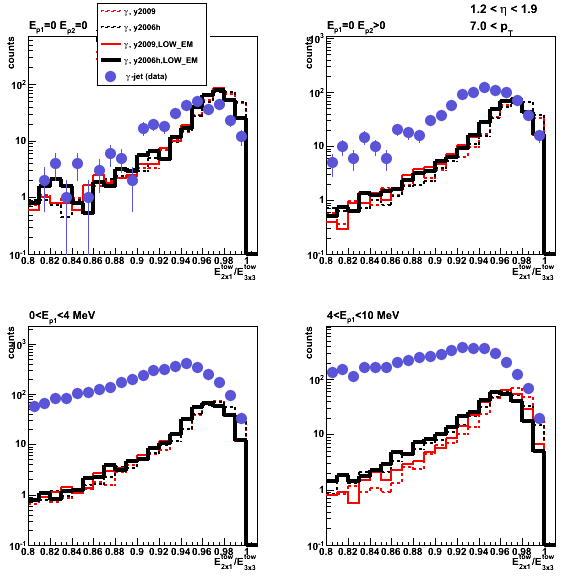
Figure 4: Shower shapes
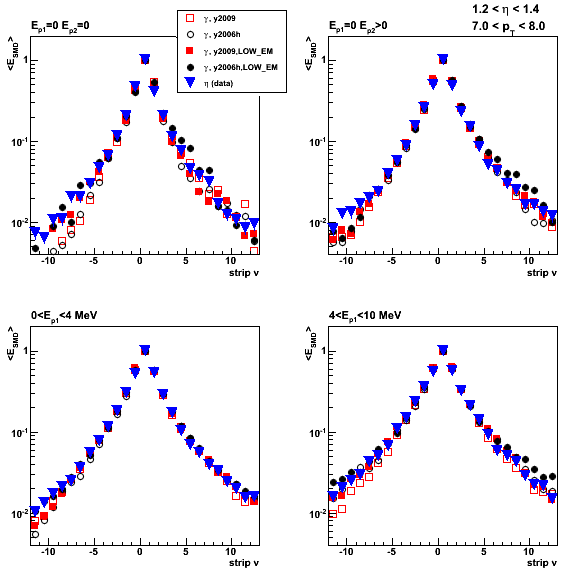
Figure 5: Shower shape ratios (v plane)
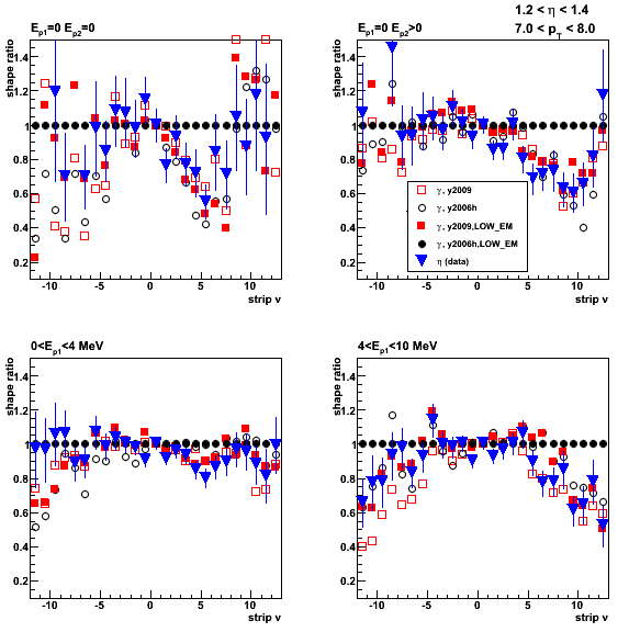
Figure 6: Shower shape ratios (u plane)

Figure 7: Pre-shower migration (1.2 < eta < 1.9; no pt cuts)

12 Dec
December 2009 posts
2009.12.01 BEMC 1x1, 2x1, 2x2, 3x3 clustering
Monte-Carlo setup:
- Throwing one photon per event
- Full y2009 STAR geometry configurations with/without LOW_EM option
- Throw particles flat in eta (-1,1), phi (0, 2pi),
with energy: 30GeV with flat (+/-0.5 GeV) spread - bfc.C options:
trs,fss,y2009a,Idst,IAna,l0,tpcI,fcf,ftpc,Tree,logger,ITTF,Sti,MakeEvent,McEvent,
geant,evout,IdTruth,tags,bbcSim,tofsim,emcY2,EEfs,
GeantOut,big,-dstout,fzin,-MiniMcMk,beamLine,clearmem,eemcDB,VFPPVnoCTB - Use fixed (7%) sampling fraction in StEmcSimpleSimulator.cxx
mSF[0] = 1/0.07;
mSF[1] = 0.;
mSF[2] = 0.; - Vertex z=0
- 50K/per particle type
data base settings (same settings in bfc.C (Jan's trick) and in my MuDst reader):
dbMk->SetFlavor("sim","bemcPed");
dbMk->SetFlavor("Wbose","bemcCalib");
dbMk->SetFlavor("sim","bemcGain");
dbMk->SetFlavor("sim","bemcStatus");
Note: for BEMC ideal pedSigma set to 0, so effectively
there is no effect when I apply 3-sigma threshold above pedestal.
Figure 1: Energy sampling of various cluster in the Barrel EMC
E_reco is the total energy in the BEMC towers from mMuDstMaker->muDst()->muEmcCollection()
eta_thrown - rapidity of the thrown photon from the Geant record
Cuts: |eta| < 0.97 && |eta|>0.01 && total energy s.f. > 0.055
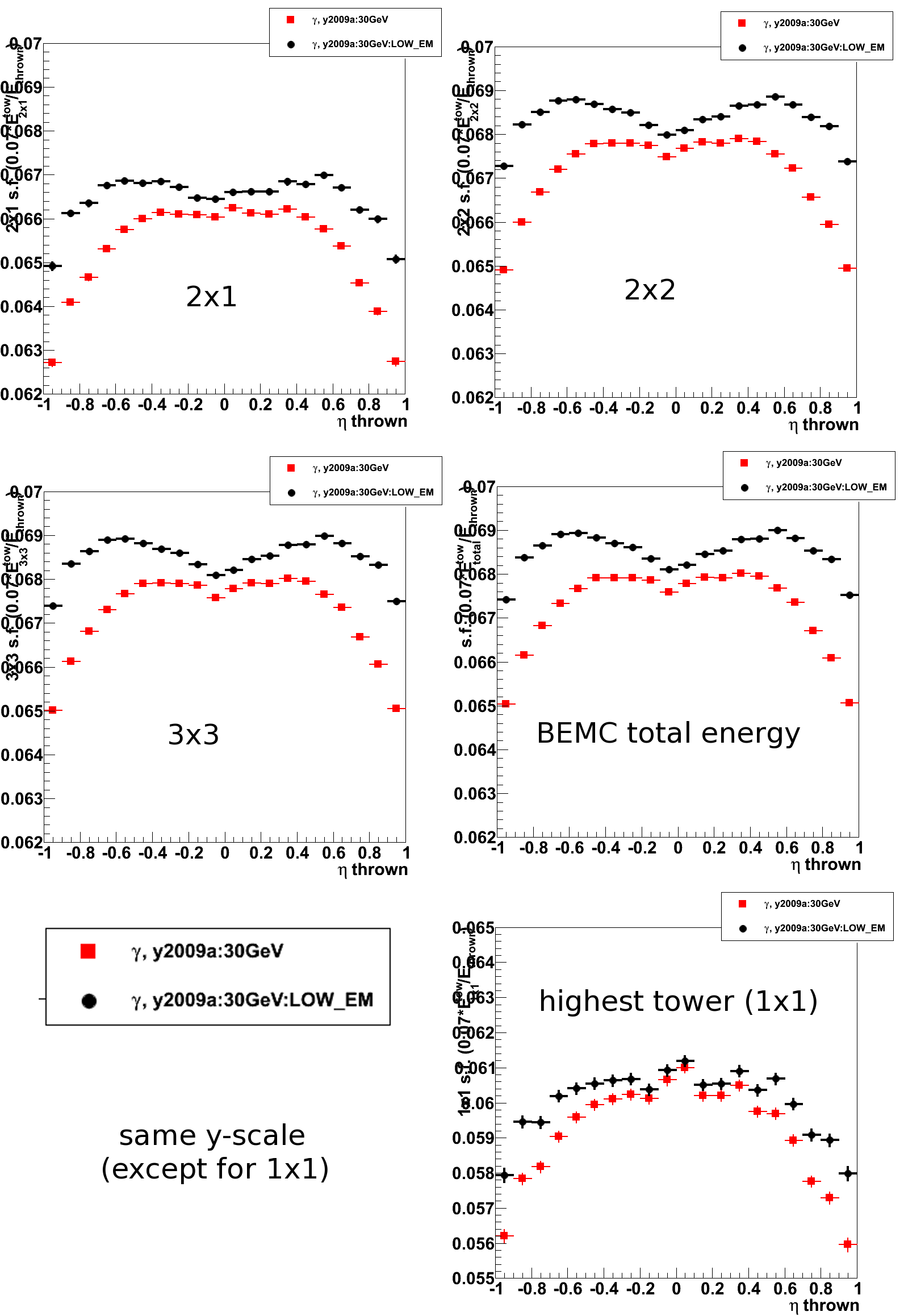
Figure 2: Various cluster energy ratios
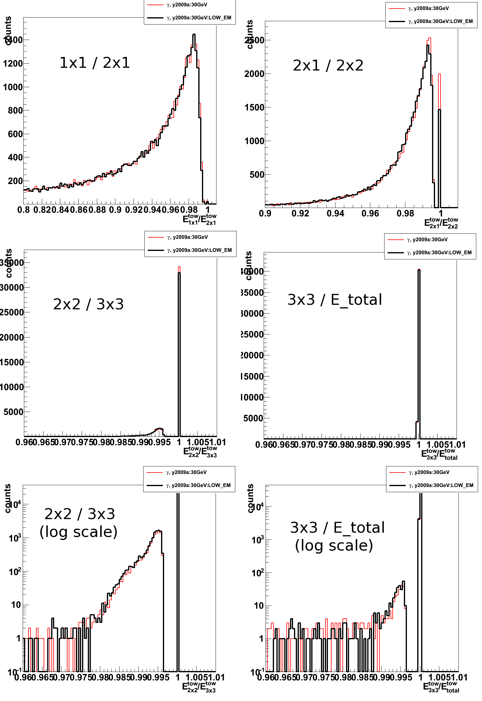
2009.12.07 Low EM study: LOW_EM option, 100KeV cuts, and DCUTE=100KeV
Conclusions/dicsussion at the emc2 hypernew
http://www.star.bnl.gov/HyperNews-star/get/emc2/3369.html
http://www.star.bnl.gov/HyperNews-star/get/emc2/3375.html
Monte-Carlo setup:
- Throwing one photon per event
- Full STAR y2006h (latest EEMC, v6.1 and TPC, v04 geometries)
- Throw particles flat in eta (1.08, 2.0), phi (0, 2pi), and energy (5-35 GeV)
- Using A2Emaker to get reconstructed Tower/SMD energy (no EEMC SlowSimulator in chain)
- Vertex z=0
- ~50K/per particle type
- Non-zero energy: 3 sigma above pedestal
GEANT EM cuts list (default values in GeV)
- CUTGAM - cut for gammas (GEANT default = 0.001)
- CUTELE - cut for electrons (GEANT default = 0.001)
- CUTHAD - cut for charged hadrons (GEANT default = 0.01)
- CUTNEU - cut for neutral hadrons (GEANT default = 0.01)
- CUTMUO - cut for muons (GEANT default = 0.01)
- BCUTE - cut for electron brems (GEANT default = CUTGAM)
- BCUTM - cut for muon brems (GEANT default = CUTGAM)
- DCUTE - cut for electron delta-rays (GEANT default = 10^4)
- DCUTM - cut for muon delta-rays (GEANT default = 10^4)
- LOSS - energy loss
- STRA - energy fluctuation model
- Birks law parameters (Tracking Parameters)
MODEL BIRK1; RKB BIRK2; C BIRK3
Low EM cut configurations (values in GeV)
-
NoCuts: Default STAR geometry EM cuts
Endcap EMC setup is quite non-uniform
(all cuts are set via "Call GSTPAR (ag_imed,'CutName', Value)":- Block EMGT: 30 degree megatile
CUTGAM = 0.00001
CUTELE = 0.00001 - Block ESCI: active scintillator (polystyrene) layer
CUTGAM = 0.00008
CUTELE = 0.001
BCUTE = 0.0001
CUTNEU = 0.001
CUTHAD = 0.001
CUTMUO = 0.001
c-- Define Birks law parameters
BIRK1 = 1.
BIRK2 = 0.013
BIRK3 = 9.6E-6 - Block ELED : lead absorber plate
CUTGAM = 0.00008
CUTELE = 0.001
BCUTE = 0.0001
CUTNEU = 0.001
CUTHAD = 0.001
CUTMUO = 0.001 - Block EALP: thin aluminium plate in calorimeter cell
CUTGAM = 0.00001
CUTELE = 0.00001
LOSS = 1.
STRA = 1. - Block EHMS: defines the triangular SMD strips
CUTGAM = 0.00008
CUTELE = 0.001
BCUTE = 0.0001
c-- Define Birks law parameters
BIRK1 = 1.
BIRK2 = 0.0130
BIRK3 = 9.6E-6
- Block EMGT: 30 degree megatile
- 100KeV: All cuts are set to 100KeV
CUTGAM = 0.0001
CUTELE = 0.0001
BCUTE = 0.0001
BCUTM = 0.0001
DCUTE = 0.0001
DCUTM = 0.0001 - DCUTE: All cuts are set to 10KeV, except electron delta-rays (DCUTE = 100KeV)
CUTGAM = 0.00001
CUTELE = 0.00001
BCUTE = 0.00001
BCUTM = 0.00001
DCUTE = 0.0001
DCUTM = 0.00001 - LOW_EM: All cuts are set to 10KeV
CUTGAM = 0.00001
CUTELE = 0.00001
BCUTE = 0.00001
BCUTM = 0.00001
DCUTE = 0.00001
DCUTM = 0.00001
Figure 1: Endcap EMC sampling fraction for different cluster sizes:
1x1, 2x1, 3x3, and total energy in the EEMC
Lower right plot shows total s.f. vs. photon thrown energy
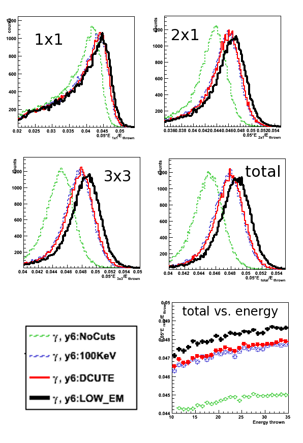
Figure 2: Endcap EMC shower shapes
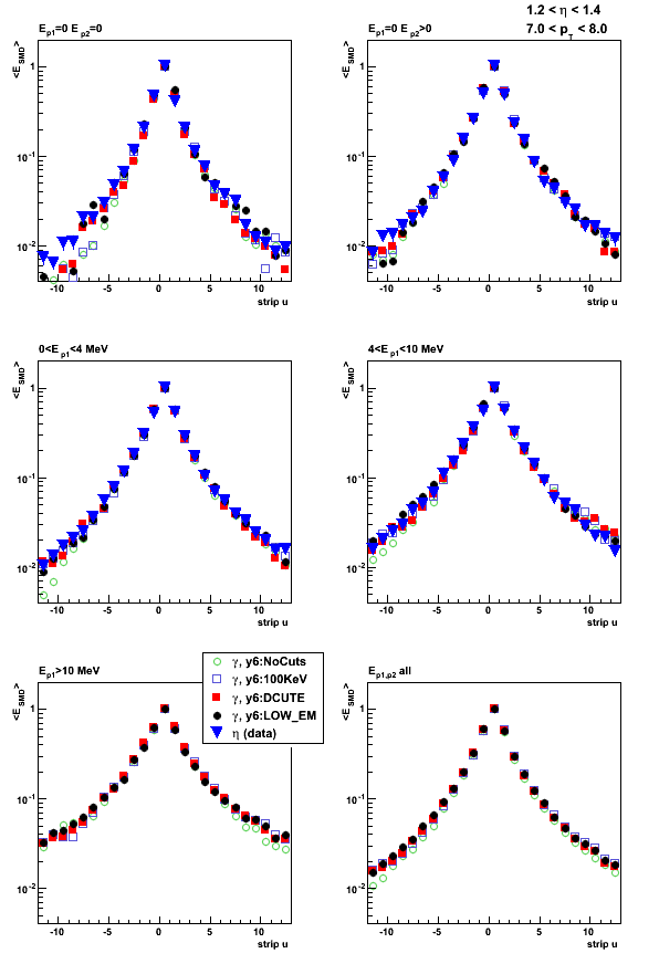
Figure 3: Endcap EMC shower shape ratios
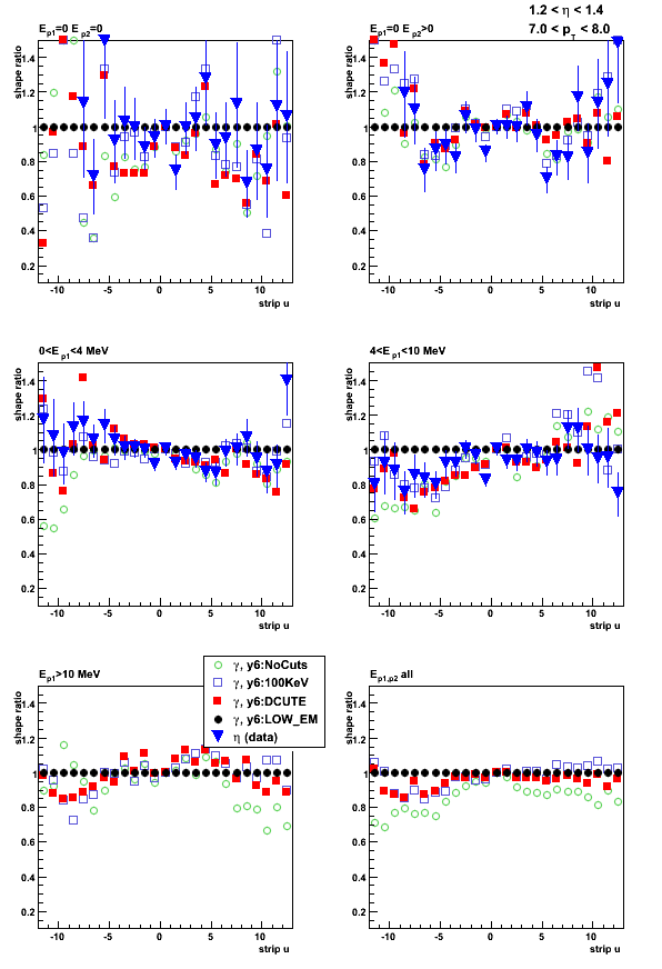
2009.12.08 Low EM timing study: 10KeV vs. 100KeV cut settings
Conclusions/dicsussion at the emc2 hypernew:
http://www.star.bnl.gov/HyperNews-star/get/emc2/3374.html
List of LOW_EM cuts and defaults
Low EM cut configurations (values in GeV)
- NoCuts: Default STAR geometry EM cuts
- LOW_EM:100KeV: All LOW_EM cuts are set to 100KeV
- LOW_EM:10KeV: (default) LOW_EM cuts (10KeV)
- DCUTE: All cuts are set to 10KeV, except for electron delta-rays DCUTE = 100KeV
QCD hard processes timing
Pythia QCD Monte-Carlo:
- Pythia pp@500GeV 2->2 hard QCD processes for parton pt>15GeV
- Full STAR y2009a (latest EEMC, v6.1 and TPC, v04 geometries)
- 50 events per file, 100 jobs
- BFC options and kumac details are here
Figure 1: QCD Total (GEANT/GSTAR+bfc) timing (seconds/event)
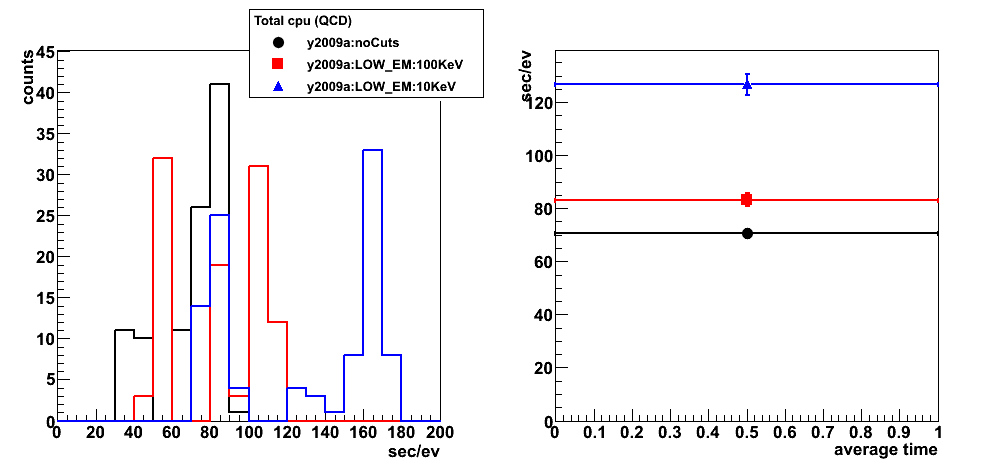
Figure 2: QCD GEANT/GSTAR timing (seconds/event)
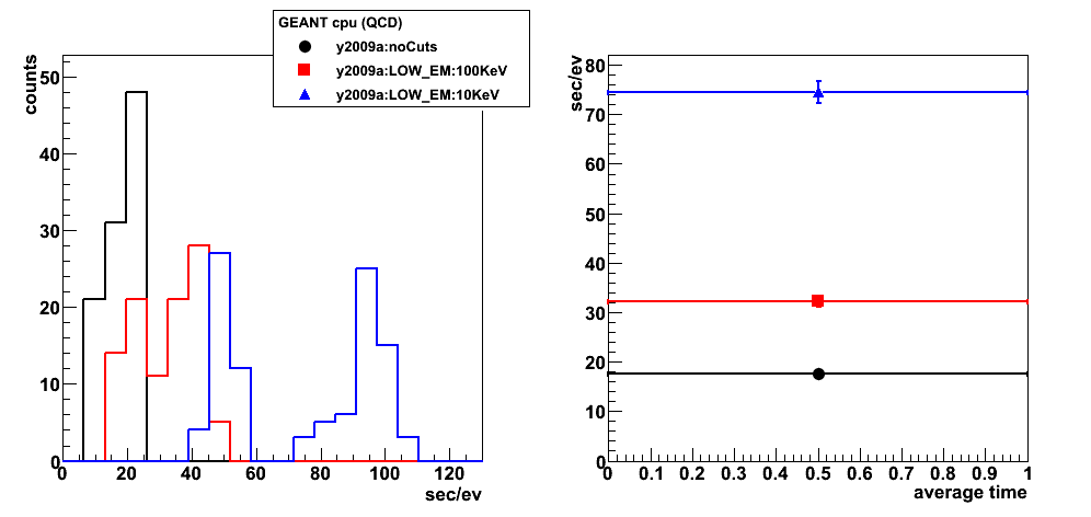
Figure 3: QCD bfc.C timing (seconds/event)
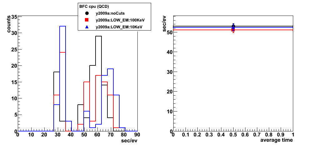
EEMC single photon timing
EEMC single photons Monte-Carlo
- One photon per event
- Full STAR y2006h (latest EEMC, v6.1 and TPC, v04 geometries)
- flat in eta (1.08, 2.0), phi (0, 2pi), and energy (5-35 GeV)
- 250 events per file, 200 jobs
Figure 4: EEMC single photon Total (GEANT/GSTAR+bfc) timing (seconds/event)
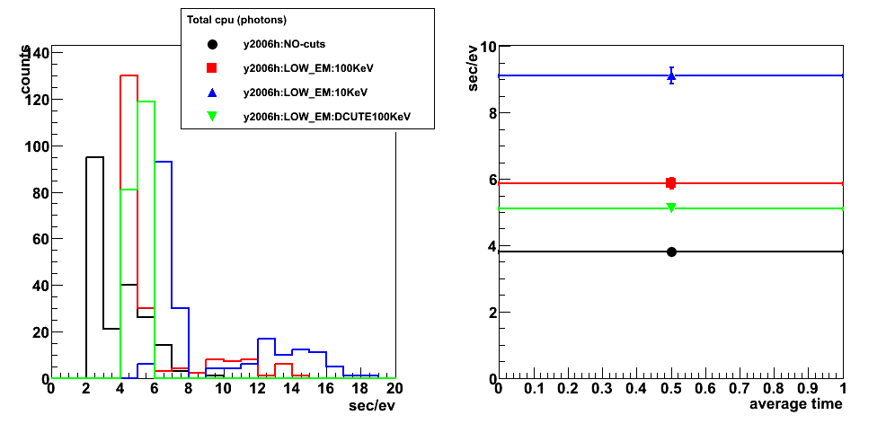
Figure 5: EEMC single photon GEANT/GSTAR timing (seconds/event)

Figure 6: EEMC single photon bfc.C timing (seconds/event)
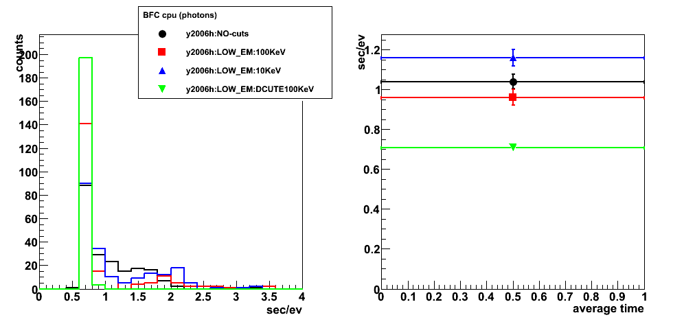
2009.12.17 Ecalgeo-v6.2: embedded LOW_EM cuts in the calorimeter geometry
Monte-Carlo setup:
- Throwing one photon per event
- Full STAR y2006h (latest EEMC-v6.2 and BEMC with LOW_EM cuts, rest of geometry from CVS)
- Throw particles flat in eta (1.08, 2.0), phi (0, 2pi), and energy (5-35 GeV)
- Using A2Emaker to get reconstructed Tower/SMD energy (no EEMC SlowSimulator in chain)
- Vertex z=0
- ~50K/per particle type
- Non-zero energy: 3 sigma above pedestal
Figure 1: (left) Endcap EMC sampling fraction (total calorimeter energy), (right) SMD-u sampling fraction
Red: (previous) ecalgeo-v6.1 with global LOW_EM option
(Note: same points as in this post, Fig. 1 lower left, label y6:LOW_EM)
Black: (new) ecalgeo-v6.2 (embedded LOW_EM cuts), no global LOW_EM option
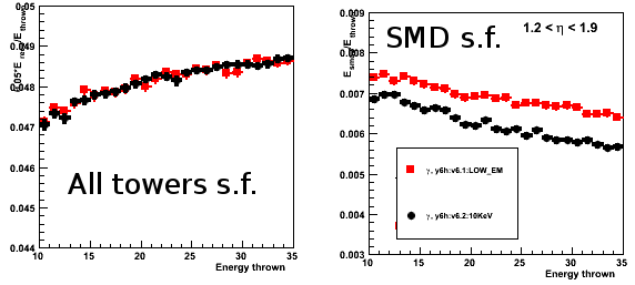
Figure 2: Pre-shower migrations
There is only a few events with pre1>4MeV with new simulations: potential problem with TPC geometry?
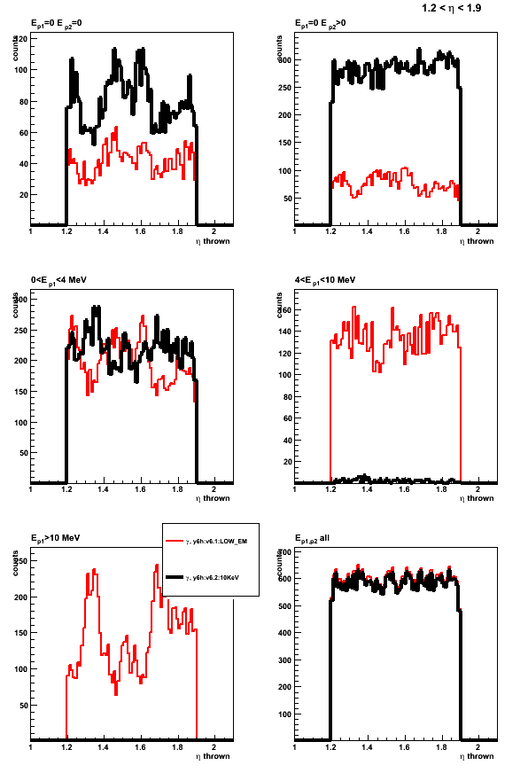
2009.12.20 Ecalgeo-v6.2: embedded LOW_EM cuts after TPC/EEMC overlap fix
Monte-Carlo setup:
- Throwing one photon per event
- Full STAR y2006h (latest EEMC-v6.2 and BEMC with LOW_EM cuts, rest of geometry from CVS)
- Throw particles flat in eta (1.08, 2.0), phi (0, 2pi), and energy (5-35 GeV)
- Using A2Emaker to get reconstructed Tower/SMD energy (no EEMC SlowSimulator in chain)
- Vertex z=0
- ~50K/per particle type
- Non-zero energy: 3 sigma above pedestal
Results: Update for the previous tests of EMC v6.2 geometry after fixing TPC/EEMC overlap
Figure 1: Endcap EMC sampling fraction: total calorimeter energy, pre1-, pre2-, post- shower layers, and SMD-u energy
Red: (previous) ecalgeo-v6.1 with global LOW_EM option
(Note: same points as in this post, Fig. 1 lower left, label y6:LOW_EM)
Black: (new) ecalgeo-v6.2 (embedded LOW_EM cuts), no global LOW_EM option
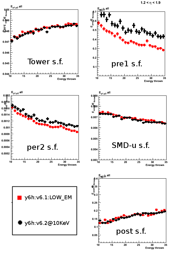
Figure 2: Pre-shower migrations
Change in TPC geometry seems to introduce a reasonable (small) change in pre-shower migration

Photon-jet simulation request
Simulation needs with y2006/y2009 geometry
specific to the photon-jet analysis
* Update version of the previous simulation
request from December 18, 2008 (see Ref. [1])
Understanding effects of trigger, material budget differences,
and throughout comparison between 2006 and 2009 data
requires to have dedicated Monte-Carlo
data samples with both y2006 and y2009 geometries.
Requested samples
We request to produce the following set of
Monte-Carlo samples for the photon-jet analysis:
- S1: 1st priority
Dedicated (gamma filtered, Refs. [2-5]) data sample
for Pythia pp@200GeV prompt photon processes
with y2006 STAR geometry configuration
and partonic pt range 2-25GeV.Simulations configured with:
-
LOW_EM option in starsim (Ref. [6]).
Low cuts on electromagnetic processes in GSTAR -
y2006h geometry tag, which includes
latest Endcap EMC (v6.1) and TPC (v4) geometry fixes. -
Pythia 6.4 CDF Tune A or Perugia tunes (6.4.22)?
-
- S2: 1st priority
Dedicated (gamma filtered, Refs. [2-5]) data sample
for Pythia pp@200GeV hard QCD processes
with y2006 STAR geometry configuration
and partonic pt range 2-25GeV.Same simulation setup as for the sample S1.
- S3: 2nd priority
Pythia pp@200GeV prompt photon and hard QCD
processes with y2009 STAR geometry configuration
and partonic pt range 2-25GeV.Same simulation setup as for the sample S1
but with y2009a geometry tag. -
S4: 3rd priority
Pythia pp@500GeV prompt photon and hard QCD
processes with y2009 STAR geometry configuration
and partonic pt range 2-25GeV.Same simulation setup as for the sample S1
but with y2009a geometry tag.
Event number, CPU time, and disk space estimates
Below I provide some estimates of CPU and disk space
which are required to produce the data samples listed above.
These estimates are based on the previous (private)
production of the MC gamma-filtered events with y2006
geometry which was done at MIT computer cluster
by Michael Betancourt (Ref. [2,4-5]):
- E1 (prompt photons)
Pythia pp@200GeV prompt photon simulations
with ~7 pb^-1 luminosity:-
~60 days running time on a single CPU
-
~17Gb of disk space to store MuDst/geant files
-
Number of (filtered) events:
~ 30K for pt range 6-9GeV
~ 15K for pt range 9-15GeV
-
- E2 (QCD hard process)
Pythia pp@200 QCD hard process simulations
with (at least) 1 pb^-1 luminosity:-
~ 620 days running on a single CPU
(less than a week on a cluster with 100 CPUs) -
~ 150Gb of disk space to store MuDst/geant files
-
Number of (filtered) events:
~ 650K for pt range 6-9GeV
~ 300K for pt range 9-15GeV
-
Notes on the estimates:
- N1
Enabling LOW_EM option in GSTAR increases
the time estimates by ~40% (Ref. [7]). - N2
Additional production of jet trees will
require a disk space on the order of < 2%
of the total size of the MuDst/geant files. - N3
Additional production of gamma trees will also
require a disk space on the order of a few percents
of the total size of the MuDst/geant files.
References
-
Previous simulation request (Date: 2008, Dec 18):
http://www.star.bnl.gov/HyperNews-star/protected/get/starspin/3596.html -
Michael's document on
"Targeted MC procedure for the gamma-jet program at STAR":
http://drupal.star.bnl.gov/STAR/system/files/20080729_gammaFilter_by_MichaelBetancourt.pdf -
simulations with filtering readiness:
http://www.star.bnl.gov/HyperNews-star/protected/get/starsimu/387/1/1/2/1/1/2/3/1.html -
Filtered photon production with y2006 geometry:
http://www.star.bnl.gov/HyperNews-star/protected/get/phana/256.html -
More details on statistics needed and disk space estimates:
http://www.star.bnl.gov/HyperNews-star/protected/get/phana/297.html -
LOW_EM option in GSTAR:
http://www.star.bnl.gov/HyperNews-star/protected/get/phana/371.html -
Time estimates with and without LOW_EM option: