- BEMC
- EEMC
- ETOF
- FCS
- FGT
- FPD & FMS & FPS
- FTPC
- FTT
- HLT
- L3
- PMD
- PP2PP
- RICH
- Roman Pot Phase II*
- SSD
- SVT
- Slow Controls
- TPC
- TRG
- Trigger Detectors
- VPD
- test
Choosing an external resistance for an IFC short
Updated on Mon, 2021-11-15 16:55. Originally created by genevb on 2021-11-15 16:36.
Under:
It is clear that when a field cage short is close to the endcap, it is best to add an external resistance to compensate for the amount of the missing resistance from the short as that would restore the current along the length of the resistor chain and only disrupt the potential at the last (outermost) rings instead of along the full length. A short near the central membrane would benefit less from this as restoring the proper current does restore the potential drop between each ring, but leaves almost all rings at a potential offset from the intended potential, essentially tilting the E field over nearly the whole volume.
But the question then comes as to whether we can decide on the best external resistance for minimizing the distortion, to align with the principle that the best distortion we can choose is the one which requires the least correction, in case we're not quite correcting it accurately. To answer that, the distortion modeling was run with a variety of locations for an IFC west 2 MOhm single-resistor short, and a variety of external resistances. The code to run this modeling has been attached as a tar file to this Drupal page in case there is interest to re-run it (e.g. for an OFC short).
Here are the results:
However, it may be more important to restrict the z range included in the distortion average, as most tracks of interest do not cross the inner pad rows at high z...
Some additional observations:
-Gene
But the question then comes as to whether we can decide on the best external resistance for minimizing the distortion, to align with the principle that the best distortion we can choose is the one which requires the least correction, in case we're not quite correcting it accurately. To answer that, the distortion modeling was run with a variety of locations for an IFC west 2 MOhm single-resistor short, and a variety of external resistances. The code to run this modeling has been attached as a tar file to this Drupal page in case there is interest to re-run it (e.g. for an OFC short).
Here are the results:
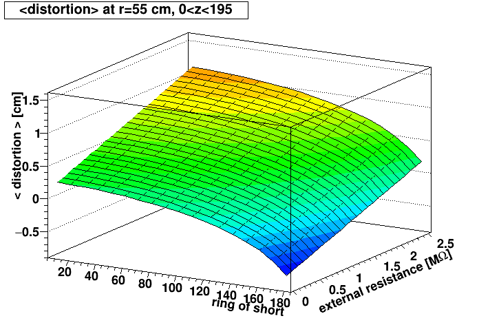
- Left: Surface plot showing the mean r-φ distortion we would get at the first iTPC pad row (radius = 55 cm) averaged over all active west-side z as a function of where the short is located ("ring of short") and how much external resistance is added.
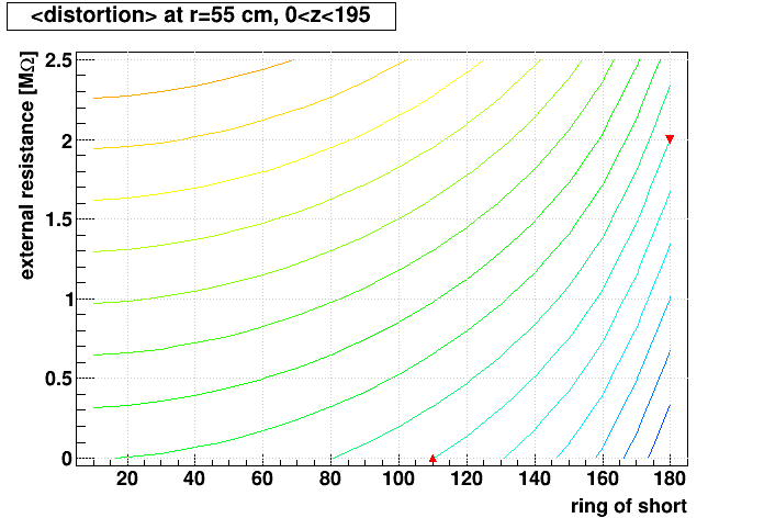
- Right: Same but drawn as contours. The curve of interest to follow, that leads to <distortion>=0, is the one that starts near (ring,external resistance) = (110,0.0) and ends near (180,2.0), as indicated by the red markers. If the short is at ring 160.5, for example, then this curve indicates an external resistance of ~1.05 MΩ minimizes the distortions averaged over all active west-side z.
However, it may be more important to restrict the z range included in the distortion average, as most tracks of interest do not cross the inner pad rows at high z...
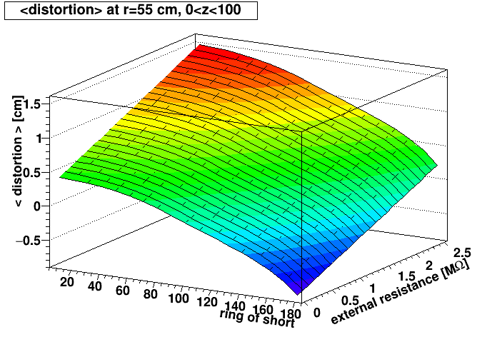
- Left: Similar surface plot, but restricting the average to 0 < z < 100 cm.
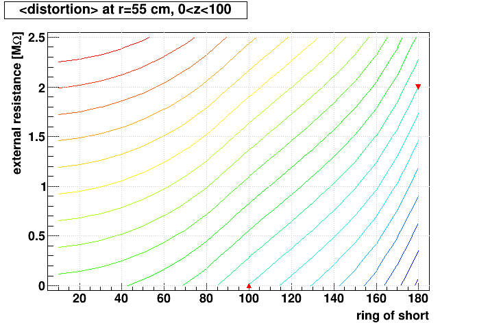
- Right: The curve of interest to follow in this contour plot, that leads to <distortion>=0, is the one that starts near (100,0.0) and ends near (180,2.0), as indicated by the red markers. If the short is at ring 160.5, then this curve indicates that an external resistance of ~1.25 MΩ minimizes the distortions averaged over 0 < z <100 cm.
Some additional observations:
- The curve of interest should always end close to (180.5,2.0), as that approaches the condition where the external resistance is no different than an internal resistance at the very end of the chain.
- The above is a simplification of what area should be integrated, as tracks with η ≠ 0 cross a variety of z at various radii, complicating the impact on their reconstruction. A track-by-track analysis of impact would be more meaningful, but a lot more work! The modeling shown here can serve as a rough guide to the best external resistance to use, but should not be taken as definitive for all physics.
- It is interesting to note that the model implies that a negative external resistance would help minimize the <distortion> when the short is closer to the central membrane (ring 0). A way to think of this is like having a short at both ends, such that the potentials are too high near the central membrane, and then too low near the endcap, so that the E field tilts one way in the region near the central membrane, isn't tilted at half the drift length, and then tilts the other way near the endcap, resulting in opposing distortions for electrons which drift the full length that serve to cancel each other. This could in principle be achieved by reducing the overall resistance of the Resistor box at the end of the Field Cage chain. The STAR TPC has (as of this documentation) had no persistent shorts near the central membrane that would warrant this approach.
-Gene
»
- Printer-friendly version
- Login or register to post comments