- BEMC
- BTOF
- DAQ
- Detector Upgrades
- EEMC
- 2007 run, hardware changes
- 2008 run preparation
- Calibrations
- EEMC Detector Operator Manual
- EEMC Maintenance/Operations Documents
- Endcap Geometry
- Endcap Geometry update (2009)
- Log of tower base and fee issues
- eemc as-built info and proto tests
- emc2-hn minutes (by Jan)
- how-to by Jan
- slow controls archive viewer
- trash
- EPD
- ETOF
- FCS
- FGT
- FPD & FMS & FPS
- FTPC
- FTT
- HFT
- HLT
- L3
- MTD
- MTD NPS Maps
- PMD
- PP2PP
- RICH
- Roman Pot Phase II*
- Run-18 calibrations
- SSD
- SVT
- Slow Controls
- TPC
- TRG
- Trigger Detectors
- VPD
- test
Endcap Geometry
Updated on Tue, 2009-10-13 12:27. Originally created by seluzhen on 2009-10-13 10:53.
Under:
Geometry definition
- Detailed description of the geometry (ver 5.1) as implemented by
Oleg Rogachevski are listed in the depth.txt file - Distribution of material as fuction of eta and phi
- Mapping of SMD strips to towers (11/20/03 jwebb)
Geant pictures of calorimeter are generated with plot_geom.kumac
-
View of EndCap caloremeter (variant C) in STAR detector

-
cross section of calorimeter towers variant C
-
cross section of lower half of calorimeter plane ZY at X=0
-
cross section of calorimeter (var.C) plane ZY at X=30cm
-
cross section at eta=2.0front part with SMD
line eta = 2.0 intersects megatile (blue) at its center
and radiators (black) at forward edge.
Hub is seen at upper edge. Each megatile extends from eta=2 to hub
as nonactive plastic and radiator extends as stainless steel. -
cross section at eta=1.086 front part with SMD
line eta = 1.086 intersects megatile at its center
and radiators at the back edge of radiator
Projective (20x25 mm) bar is seen at the lower edge of calorimeter
XXX page 9 - megatile cell structure in local coordinates, particles go along Y axis on this plot. -
regular SMD sector, V plane, blue line depicts +-15 deg. between sectors
-
edge SMD sector with cutted strips, V plane
-
cross section of 1st SMD plane
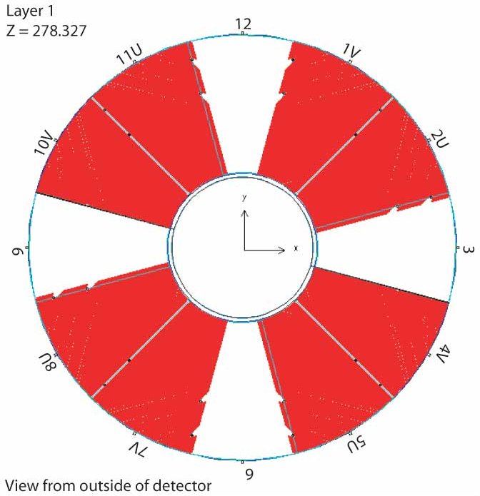
-
cross section of 2st SMD plane
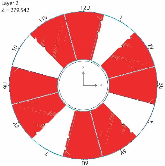
-
cross section of 3st SMD plane

-
cross section of 1st SMD plane labeled with "SUV" ordering
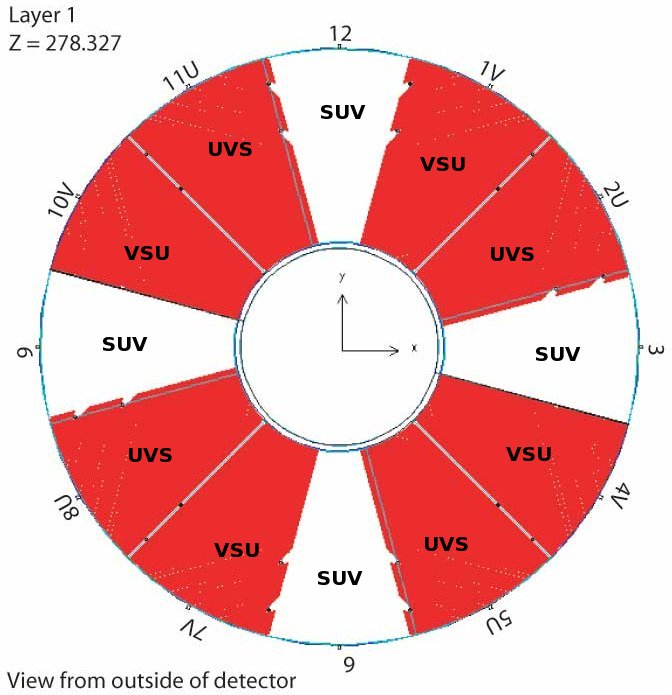
-
cross section of the gap between SMD sectors
-
cross section of the gap between tower at the sector boundary
-
cross section of the backplate
Three variants of EEMC geometry are available:
A --- lower half with only 5-8 sectors filled with scintillators
B --- fully filled lower half
C --- both halves filled with scintillators
»
- Printer-friendly version
- Login or register to post comments